Table of Contents
Advertisement
PERATOR'S
AL
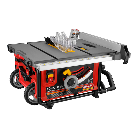
10 in. TABLE SAW
Model No.
315.218280
,&
WARNING:
To reduce the risk of injury, the
user must read and understand the operator's
manual before using this product.
Customer
Help Line: 1-800-932-3188
Sears,
Roebuck
and Co., 3333 Beverly
Rd., Hoffman
Estates,
IL 60179
USA
Visit the Craftsman
web page: www.sears.com/craftsman
987000-344
9-1-08 (REV:00)
Save this manual
for future
reference
Advertisement
Table of Contents

Related Manuals for Craftsman 21828 - Professional 10 in. Jobsite Saw


Summary of Contents for Craftsman 21828 - Professional 10 in. Jobsite Saw
- Page 1 Customer Help Line: 1-800-932-3188 Sears, Roebuck and Co., 3333 Beverly Rd., Hoffman Estates, IL 60179 Visit the Craftsman web page: www.sears.com/craftsman 987000-344 Save this manual for future reference 9-1-08 (REV:00)
-
Page 2: One Year Full Warranty
ONE YEAR FULL WARRANTY ON CRAFTSMAN TOOL If this Craftsman tool fails due to a defect in material or workmanship within one year from the date of purchase. Call 1-800-4-MY-HOME ® to arrange for free repair. If this tool is used for commercial or rental purposes, this warranty will apply for only ninety days from the date of purchase. - Page 3 [] SECURE WORK. Use clamps or a vise to hold work WARNING: Read and understand all instruc- when practical. It's safer than using your hand and tions. Failure to follow all instructions listed below, frees both hands to operate tool. may result in electric shock, fire and/or serious [] DON'T OVERREACH.
- Page 4 work or around or over the blade while blade is rotat- ing. Never use brake fluids, gasoline, petroleum-based ing. Do not attempt to remove cut material when blade products, or any solvents to clean tool. is moving. [] STAY ALERT AND EXERCISE CONTROL. Watch BLADE COASTS AFTER BEING TURNED OFF.
- Page 5 [] ALWAYS USEA PUSH STICK FOR RIPPING e) Not ripping work that is twisted or warped or does NARROW STOCK. A push stick is a device used to not have a straight edge to guide along the fence. push a workpiece through the blade instead of using IF THE POWER SUPPLY CORD IS DAMAGED, it must your hands.
-
Page 6: Symbols
Someofthefollowing symbols maybeusedonthistool.Please studythemandlearn theirmeaning. Proper interpretation ofthesesymbols willallowyouto operate thetoolbetterandsafer. SYMBOL NAME DESIGNATION/EXPLANATION Volts Voltage Current Amperes Hertz Frequency (cycles per second) Watt Power Minutes Time Alternating Current Type of current Direct Current Type or a characteristic of current No Load Speed Rotational speed, at no load Class II Construction... - Page 7 SEARS PARTS AND REPAIR SERVICE in the operator's manual, do not use this product. CENTER for repair. When servicing, use only identical Call the Craftsman Consumer Helpline at 1-800-932- replacement parts. 3188 for assistance.
-
Page 8: Extension Cords
EXTENSION CORDS SPEED AND WIRING Use only 3-wire extension cords that have 3-prong The no-load speed of this tool is approximately 5,000 rpm. grounding plugs and 3-pole receptacles that accept the This speed is not constant and decreases under a load or tool's plug. - Page 9 Anti=Kickback Pawls (radial arm and table saws} Non=Through Cuts A device which, when properly installed and maintained, Any cutting operation where the blade does not extend is designed to stop the workpiece from being kicked back completely through the thickness of the workpiece. toward the front of the saw during a ripping operation.
- Page 10 PRODUCT SPECiFiCATiONS No Load Speed ........5,000 r/min. (RPM) Blade Arbor .............. 5/8 in. Cutting Depth at 0°: ..........3-1/4 in. Blade Diameter ............10 in. Cutting Depth at 45°: ..........2-3/8 in. Blade Tilt ..............0 ° - 45 ° Rating ..........
-
Page 11: Features
KNOWYOURTABLESAW MITER GAUGE - The miter gauge aligns the wood for a cross cut. The easy-to-read indicator shows the exact See Figure 2. angle for a miter cut, with positive stops at 90 ° and 45 °. The safe use of this product requires an understanding of MITER GAUGE GROOVES - The miter gauge rides in the the information on the tool and in this operator's manual grooves on the saw table. - Page 12 OPERATING COMPONENTS WARNING: Always remove the switch key when The upper portion of the blade projects up through the the tool is not in use and keep it in a safe place. In table and is surrounded by an insert called the throat the event of a power failure, turn the switch OFF plate.
-
Page 13: Phillips Screwdriver
Thefollowing tools(notincluded ordrawnto scale) a reneeded for making adjustments: _t,l,_,l,_,J,l,l,a,l,l,l,bl,l,l,_ FRAMINGSQUARE PHiLLiPS SCREWDRIVER COMBINATION FLATBLADE SQUARE SCREWDRIVER Fig. 4... - Page 14 Thefollowing itemsareincluded withyourtablesaw: Fig. 5 A. Blade Guard ............E. Handle Assembly ............ R Push Stick ............... B. Anti-Kickback Pawls ..........G. Blade Wrench ............C. Miter Gauge ............. D. Rip Fence ..............H. Hex Key, 5 mm ............
-
Page 15: Assembly
UNPACKING MOUNTING HOLES This product requires assembly. The table saw must be mounted to a firm supporting, waist high surface such as a workbench or leg stand. [] Carefully lift the saw from the carton and place it on a Four bolt holes have been provided in the saw's base for level work surface. - Page 16 TO STORE THE TABLE SAW ACCESSORIES RAISING AND LOWERING THE TELESCOPING HANDLE See Figures 7- 8. See Figure 9. The table saw has two convenient storage areas (one on either side of the saw cabinet) specifically designed for [] To raise the handle, grasp the button while pulling the the saw's accessories.
- Page 17 TO REMOVE/REPLACE THE THROAT PLATE To place in riving knife position {or "down" position for all non=through cutting}: See Figure 11. [] Remove the throat plate. [] Lower the blade by turning the height/bevel adjusting handwheel clockwise. [] Raise the saw blade by turning the height/bevel adjust- ing handwheel counterclockwise.
- Page 18 TO CHECK SAW BLADE INSTALLATION TO INSTALL THE ANTI-KICKBACK PAWLS AND See Figure 13. BLADE GUARD See Figures 14- 15. CAUTION: To work properly, the saw blade teeth NOTE: Anti-kickback pawls should only be installed for must point down toward the front of the saw. Failure through cuts.
- Page 19 BLADE [] Reposition the blade guard assembly left or right as GUARD GUARD needed to align the spreader/riving knife with the saw LEVER blade. [] Once properly aligned, securely retighten the screws. SCREW Fig. 15 TO CHECK AND ALIGN THE SPREADER/RIVING KNIFE AND SAW BLADE See Figure 16.
- Page 20 WARNING: The table saw must be mounted to a firm supporting, waist high surface such as a work- bench or leg stand. Many illustrations in this manual PUSH STICK_ are shown with the saw unmounted for clarity. APPLICATIONS You may use this tool for the purposes listed below: [] Straight line cutting operations such as cross cutting, ripping, mitering, beveling, and compound cutting [] Dado or molding cuts with optional accessories...
- Page 21 FEATHERBOARD HOW TO MOUNT A FEATHERBOARD See Figure 19. A featherboard is a device used to help control the workpiece by guiding it securely against the table or Completely lower the saw blade. Position the rip fence to fence. Featherboards are especially useful when ripping the desired adjustment for the cut to be performed and small workpieces and for completing...
-
Page 22: Miter Cut
TYPESOF CUTO See Figure 20. There are six basic cuts: 1) the cross cut, 2) the rip cut, 3) the miter cut, 4) the bevel cross cut, 5) the bevel rip cut, and 6) the compound (bevel) miter cut. All other cuts are CROSSCUT combinations of these basic six. - Page 23 TO CHANGE BLADE DEPTH TO LOCK TO UNLOCK See Figure 21. The blade depth should be set so that the outer points of the blade are higher than the workpiece by approximately 1/8 in. to 1/4 in. but the lowest points (gullets) are below the top surface.
- Page 24 LOCKING _1_ WARNING:Toreduce the riskof injury, a lways LEVER makesurethe ripfence RIP FENCE is parallel to the blade before beginning any operation. TABLE TO SET THE RiP FENCE SCALE INDICATOR THE BLADE See Figure 24. Begin with the blade at a zero angle (straight up). [] Unplug the saw.
- Page 25 TO USE THE SLiDiNG TABLE EXTENSION TO USE THE OUTFEED SUPPORT See Figure 27. See Figure 28. Increase the length of the saw table by using the table The outfeed support slides to give the operator additional extension. support for cutting long workpieces. [] Set the rip fence to 13 in.
-
Page 26: Miter Gauge Groove
ADJUSTING HEELING (PARALLELING) BLADE MITER GAUGE GROOVE BOLTS(3) See Figures 29 - 31. WARNING: The blade must be square so the wood does not bind resulting in kickback. Failure to do so could result in serious personal injury. Do not loosen any bolts for this adjustment until you have checked with a square and made test cuts to be sure adjustments are necessary. - Page 27 MAKING CUTS The blade provided with your saw is a high-quality combi- nation blade suitable for ripping and cross cut operations. SWITCH Carefully check all setups and rotate the blade one full revolution to assure proper clearance before connecting saw to power source. WARNING: Do not use blades rated less than the speed of this tool.
-
Page 28: A Rip Cut
MAKING A RIP CUT MAKING A MITER See Figure 34. See Figure 35. WARNING: Make sure the blade guard assembly WARNING: Make sure the blade guard assembly is installed and working properly to avoid serious is installed and working properly to avoid possible possible injury. - Page 29 BEVELCROSSCUT MAKING A BEVEL CROSS See Figures 36 - 37. BLADE ANGLED WARNING: Make sure the blade guard assembly MITER GAUGE STRAIGHT is installed and working properly to avoid possible serious injury. [] Remove the rip fence by lifting the locking lever. [] Unlock the bevel locking lever.
- Page 30 [] Once thebladehasmadecontactwiththeworkpiece, Set the miter gauge to the desired angle and tighten usethehandclosest t othe ripfenceto guideit. Make the lock knob. suretheedgeoftheworkpiece remains in solidcontact Make sure the wood is clear of the blade before turning on the saw. withboththeripfenceandthesurface ofthetable.If ripping a narrow piece,usea pushstickto movethe Turn the power switch to the on position.
-
Page 31: Makinga Large Panel Cut
MAKING A LARGE PANEL CUT MAKING A NON=THROUGH See Figure 40. See Figure 41. Make sure the saw is properly secured to a work surface Non-through cuts can be made with the grain (ripping) or to avoid tipping from the weight of a large panel. across the grain (cross cut). -
Page 32: Makinga Dado Cut
[] Turn the power switchto theon position. Remove the spreader/riving knife. [] Whenthecutis made, t urnthesawoff. Waitforthe Mount the dado blade, according to manufacturer bladeto cometo a complete stopbefore removing t he instructions, using the blade and chippers appropriate workpiece. for the desired width of cut. -
Page 33: Adjustments
ARBOR BLADE BLADE A_, WARNING: Before performing any adjustment, make sure the tool is unplugged from the power SHAFT WASHER supply and the switch is in the OFF ( O ) position. Failure to heed this warning could result in serious personal injury. - Page 34 TO SETTHE BLADEAT 0° AND 45° 0° ADJUSTMENT BOLT See Figures 46 - 47. BLADE COMBiNATiON The angle settings of your saw have been set at the fac- tory and, unless damaged in shipping, should not require LOCKING setting during assembly. After extensive use, it may need LEVER BEVEL SQLiARE...
- Page 35 TO ADJUST THE MITER GAUGE TO CHECK THE ALIGNMENT OF THE RIP FENCE See Figure 48. TO THE BLADE See Figure 49. You can set the miter gauge at 0° and plus or minus 45 ° with the miter gauge stop pin and adjustable stop screws. WARNING: To reduce the risk of injury, always NOTE: The miter gauge provides close accuracy in...
-
Page 36: Maintenance
[] Periodically check all clamps, nuts, bolts, screws, and WARNING: When servicing, use only identical belts for tightness and condition. Make sure the throat replacement parts. Use of any other parts may create plate is in good condition and in position. a hazard or cause product damage. - Page 37 PROBLEM CAUSE SOLUTION Excess vibration. Blade is out of balance. Replace blade. Blade is damaged. Replace blade. Saw is not mounted securely. Tighten all hardware. Work surface is uneven. Reposition on flat surface. Blade is warped. Replace blade. Rip fence does not move smoothly. Rip fence not mounted correctly.
- Page 38 PROBLEM CAUSE SOLUTION Saw does not make accurate Positive stops inside cabinet need Adjust positive stops. 90 ° or 45 ° cuts. adjusting (Bevel Cuts). Adjust the miter gauge. Miter gauge is misaligned (Miter Cuts). Height/bevel adjusting hand- Clean the gears or screw post. Gears or screw post inside wheel is hard to turn.
- Page 39 CRAFTSMAN 10 in. TABLE SAW - MODEL NUMBER 315.218280 Figure A...
- Page 40 CRAFTSMAN 10 in. TABLE SAW - MODEL NUMBER 315.218280 TABLE SAW or when ordering repair parts. he model number will be found on a plate attached to the motor housing. Always mention the model number in all correspondence regarding your...
- Page 41 CRAFTSMAN 10 in. TABLE SAW - MODEL NUMBER 315.218280 TABLE SAW or when ordering repair parts. he model number will be found on a plate attached to the motor housing. Always mention the model number in all correspondence regarding your...
- Page 42 CRAFTSMAN 10 in. TABLE SAW = MODEL NUMBER 315.218280...
- Page 43 CRAFTSMAN 10 in. TABLE SAW - MODEL NUMBER 315.218280 TABLE SAW or when ordering repair parts. he model number will be found on a plate attached to the motor housing. Always mention the model number in all correspondence regarding your...
- Page 44 CRAFTSMAN 10 in. TABLE SAW - MODEL NUMBER 315.218280 TABLE SAW or when ordering repair parts. he model number will be found on a plate attached to the motor housing. Always mention the model number in all correspondence regarding your "1...
- Page 45 CRAFTSMAN 10 in. TABLE SAW - MODEL NUMBER 315.218280 Figure C...
-
Page 46: Parts List
CRAFTSMAN 10 in. TABLE SAW - MODEL NUMBER 315.218280 TABLE SAW or when ordering repair parts. he model number will be found on a plate attached to the motor housing. Always mention the model number in all correspondence regarding your...
Need help?
Do you have a question about the 21828 - Professional 10 in. Jobsite Saw and is the answer not in the manual?
Questions and answers