Table of Contents
Advertisement
Quick Links
SHERWOOD INDUSTRIES IS AN ENVIRONMENTALLY RESPONSIBLE COMPANY. THIS MANUAL IS PRINTED ON RECYCLED PAPER.
PLEASE KEEP THESE INSTRUCTIONS FOR FUTURE REFERENCE
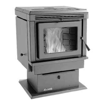
PELLET STOVE
EF2
Freestanding, Fireplace Insert
& Built-In Heater
OWNER'S MANUAL
PLEASE READ THIS ENTIRE MANUAL BEFORE INSTALLATION
AND USE OF THIS PELLET BURNING ROOM HEATER. FAILURE TO
FOLLOW THESE INSTRUCTIONS COULD RESULT IN PROPERTY
DAMAGE, BODILY INJURY, OR EVEN DEATH.
Contact your building or fire officials about restrictions and
installation inspection requirements in your area.
EF-119
Advertisement
Table of Contents

Related Manuals for Enviro EF-119


Summary of Contents for Enviro EF-119
- Page 1 PLEASE READ THIS ENTIRE MANUAL BEFORE INSTALLATION AND USE OF THIS PELLET BURNING ROOM HEATER. FAILURE TO FOLLOW THESE INSTRUCTIONS COULD RESULT IN PROPERTY DAMAGE, BODILY INJURY, OR EVEN DEATH. Contact your building or fire officials about restrictions and installation inspection requirements in your area. EF-119...
-
Page 2: Table Of Contents
Safety Warnings And Recommendations...4 Operating Instructions...6 Automatic Safety Features...6 Slider/Damper Setting...6 Operating Your Pellet Stove...7 Turning Your Pellet Stove Off...7 Routine Cleaning and Maintenance...8 Installation...11 Deciding Where to Locate your Pellet Appliance...11 Removing Pellet Stove From Pallet...11 Dimensions - Freestanding...12 Dimensions - Fireplace Insert and Built-In Heater...12... -
Page 3: Introduction
UALITY Pellet quality is important, please read the following: Your enviro pellet stove has been designed to burn wood pellets only. Do not use any other type of fuel, as this will void any warranties stated in this manual. The performance of your pellet stove is greatly affected by the type and quality of wood pellets being burned. -
Page 4: Important Safety Data
CLEANING: There will be some build up of fly ash and small amounts of creosote in the exhaust. This will vary due to the ash content of the fuel used and the operation of the stove. It is advisable to inspect and clean the exhaust vent semi-annually or every two tons of pellets. - Page 5 GLASS: Do not abuse the glass by striking or slamming the door. Do not attempt to operate the stove with broken glass. The stove uses ceramic glass. Replacement glass must be purchased from an ENVIRO dealer. Do not attempt to open the door and clean the glass while the unit is in operation or if glass is hot.
-
Page 6: Operating Instructions
To compensate for the fan cycling action that may occur, turn up the blower control proportionately to the heat output. D. If the power goes out, the unit will stop running. When the power comes back on, the stove will not restart unless the exhaust temperature is still above 120°F (49 °C). -
Page 7: Operating Your Pellet Stove
The blowers will continue to run and cool the stove. SPECIAL NOTES: If the stove is left in the manual mode after the green light comes on, the auger will continue to feed pellets. Pellets may over flow the burn-pot after the fire goes out and also re-light. -
Page 8: Routine Cleaning And Maintenance
Then dispose of the scrapped ashes from the liner and from inside the burn pot. Place the burn pot back into the stove, making sure that the pipes are properly inserted into the burn pot and the front tabs are placed in the firebox. Place the liner back into the burn-pot making sure that the ignitor hole in the liner is aligned with the ignitor tube. - Page 9 FREESTANDING ASH PAN: The EF2 pellet stove freestanding’s ash pan is located under the burner, in the pedestal, and has a latching mechanism to secure it. To remove the ash pan, unlock the latch on the ash pan and then pull the pan out.
-
Page 10: Post Season Clean-Up
BLOWER MECHANISMS (season) Unplug the stove then open the right and left side panels to access the two blowers. Vacuum all dust from motors. Only the convection blower motor (on the right side of the stove) will require lubrication. -
Page 11: Installation
ELLET TOVE To remove your new stove from its pallet, open the left and right side panels. To open the side panels remove the ash pan cover from the magnets located below the door. Remove the two (2) T-20 screws located at the bottom corners of the left and right side panels. -
Page 12: Dimensions - Freestanding
IMENSIONS REESTANDING �� ���� ��� IMENSIONS IREPLACE NSERT AND ��� ���� ��������� ��� �� ��� ���� ��������� ��� ���� ��� Figure 7: Dimensions of EF2 Fireplace Insert and Built-In Heater. Installation � � � � �� � � � � ����... -
Page 13: Clearances To Combustibles - Freestanding
LEARANCES TO OMBUSTIBLES When installing this unit on a combustible floor (for example linoleum, hardwood flooring) a non- combustible hearth pad must be under the unit. The pad must extend at least the width of the appliance [22” (558 mm)] and at least the depth of the appliance plus 6” (153 mm) in front of the appliance [29 3⁄4”... -
Page 14: Clearances To Combustibles - Built-In Heater
LEARANCES TO OMBUSTIBLES Refer to Figures 10 and 11. Side wall to unit Mantel projection Mantel to top of unit Top facing to unit Side facing to unit Floor protection (on either side and to the front must be protected by non-combustible material) Sides and rear walls to standoffs: Recess depth:... -
Page 15: Vent Termination Requirements
ERMINATION EQUIREMENTS IT IS RECOMMENDED THAT YOUR PELLET STOVE BE INSTALLED BY AN AUTHORIZED DEALER/INSTALLER. Table 1: Use in conjunction with Figure 15 for allowable exterior vent termination locations. Letter Minimum Clearance 24 in (61 cm) 48 in (122 cm) -
Page 16: Fresh Air Intake
UTSIDE RESH ONNECTION Outside fresh air is mandatory when installing this unit in airtight homes and mobile homes. When connecting to an outside fresh air source, do not use plastic or combustible pipe. A 15⁄8” minimum (42 mm) ID (inside diameter) steel, aluminum or copper pipe should be used. -
Page 17: Mobile Home Installation - Freestanding
CAUTION: THE STRUCTURAL INTEGRITY OF THE MANUFACTURED HOME FLOOR, WALL AND CEILING/ROOF MUST BE MAINTAINED. ORNER HROUGH NSTALLATION Installation REESTANDING ENVIRO EF2 HEARTH PAD FLOORING STEEL FRAME Figure 19: Mobile home installation. REESTANDING Fresh Air Intake 2" (5 cm) 2"... -
Page 18: Horizontal Exhaust Through Wall Installation - Freestanding
Equipment. Only use venting of L or PL type with an inside diameter of 3 or 4 inches (7.6 or 10.1 cm). 1. Choose a location for your stove that meets the requirements stated in this manual and allows installation with the least amount of interference to house framing, plumbing, wiring, etc. -
Page 19: Through Wall With Vertical Rise And Horizontal Termination Installation - Freestanding
• Some horizontal through wall installations may require a “T” and 3 to 5 feet (91 to 152 cm) of vertical pipe outside the building to help naturally draft in the unit. • This may be required if a proper burn cannot be maintained, after the stove has been tested and the airflow set. -
Page 20: Inside Vertical Installations - Freestanding
NSIDE ERTICAL NSTALLATIONS 1. Choose a stove location that is ideal. See the section “D 2. Place a non-combustible hearth pad where necessary. 3. Place the unit on the hearth pad (if installed on a carpeted surface) and space the unit in a manner so when the pellet vent is installed vertically, it will be 3”... -
Page 21: Hearth Mount Installation - Freestanding
���� ��� 6" (15 cm) �������� �� ����� �� ��������� ����� ����� Non-combustible floor protection. EARTH OUNT NSTALLATION ��������� ��� ��������� ������ ������ ���� ���� �������� �� ����� ������� ������ ������ ��� ������ ��� �� ����� ������� ���� �� ��������� �� �������... -
Page 22: Masonry Fireplace Installation - Fireplace Insert
Figure 28: Freestanding hearth mount installation overview. ASONRY IREPLACE NSTALLATION The fireplace insert model requires a surround panel and a pedestal. When installing this unit, ensure that the pedestal is removed from the inside of the hopper and installed on the bottom of the unit (see “P ”). - Page 23 If the fireplace insert does not fit into a zero clearance fireplace, we recommend you use an ENVIRO freestanding model and install as a hearth mounted unit. Install a 3” (76 mm) flex pipe from the stove to the top of the chimney (see “H Installation ���������...
-
Page 24: Installation For A Built-In Heater
NSTALLATION UILT Combustible materials and structure Surround Panel 6" (15 cm) Existing floor Non-combustible (combustible) floor protection. 3" (7.5 cm) Pedestal Figure 30: Built-in heater installation. NSTALLATION OF ONTROL When installing the control panel into the surround panel, the surround does not need to be assembled. The control board will be found in behind the firebox. -
Page 25: Installation And Removal Of The Surround Panels - Fpi And Bih
NSTALLATION AND EMOVAL OF Two (2) pieces make up one (1) corner bracket 1. Assemble the trim set using the corner hardware and screws supplied in the surround panel packaging. Install corner hardware into the side trim pieces, then push them into the top trim. Do not over-tighten the corners or the side trim cannot be removed during servicing. -
Page 26: Slider/Damper Installation
AMPER NSTALLATION Not for installation in Germany. This is used to regulate the airflow through the pellet stove. 1. Remove the slider rod (short rod with knob and nuts) from their package and open the left side panel. 2. Remove the knob and outer nut from the knob. Push the rod through the hole in the slider. Place the lock nut on the rod and tighten, leaving a 3. -
Page 27: Troubleshooting
Attempt to bypass the switch by inserting a jumper wire between the dual black wires (middle of the switch) and the single grey wire (left side of the stove) that attach to the back of the switch. Plug the stove back in. - Page 28 If the unit fails to operate, by-pass the auto side of the switch by inserting a jumper wire between the dual black wires and the dual brown wires located on the back of the switch. Plug the stove back in.
- Page 29 Check the condition of the vacuum hose (located on the left side of the stove). It should not be cracked or torn and should be installed on the top air inlet tube on the vacuum sensor.
- Page 30 Check the 120°F (49°C) temperature sensor by removing one of the brown wires from the sensor. The unit should shut down right away as long as the switch is in the AUTO position. If the stove shuts down, replace the 120°F (49°C) sensor. If the stove does not shut down, test the switch.
-
Page 31: Wiring Diagram
Wiring Diagram F (71 Purple Convection Purple Temperature Black Switch F (49 Exhaust Temperature Switch Exhaust / Combustion Blower Ignitor F (49 Ignitor Temperature Switch Auger Convection Timer Blower Orange Black Blue White White Yellow Yellow High Limit Temperature Brown Brown Blue Vacuum... -
Page 32: Parts List
Reference Description Number 120°F (49°C) Ceramic Fan Temp Sensor Freestanding Fan Controller Knob Domestic Power Cord - 115V Auger Motor - 115V Convection Blower -115V Convection Blower Impeller Convection Blower Insulator (Gasket) Combustion Main Impeller Combustion Cooling Impeller Combustion Blower Mounting Gasket Combustion Blower Housing Gasket Fan Temperature Sensor 160°F (71°C) Ignition Temperature Sensor 120°F (49°C) Ceramic... - Page 33 Steel Brick Lining Fireplace Insert Cabinet Side Left Parts List Part Number EF-057 EF-058 EF-060 EF-061 EF-064 EF-065 EF-066 EF-067 EF-068 EF-069 EF-074 EF-074A EF-096 EF-097 EF-102 EF-103 EF-104 EF-105 EF-106 EF-107 EF-108 EF-113 EF-115 EF-117 EF-119 EF-122 EF-125 EF-126 EF-130 EF-132...
- Page 34 Pedestal & Ash Pan Gasket 10’ (3 m) Control Panel Door Thermostat Dial-A-Fire 60° Exterior Exhaust Adaptor Built-In Heater Standoffs (Set of 2) Enviro Logo Gel Decal Control Panel Touch Latch Combustion Blower Exhaust Tube Stainless Steel Burn Pot Liner - Standard Convection Blower Mount...
-
Page 35: Parts List - Options
Parts List - Options Reference Description Number Log Set Decorative Trivet - Painted Decorative Trivet - Gold Louvre Trim - Brass Louvre Trim - Nickel Firebox Pillar Trim (Left & Right) - Painted Firebox Pillar Trim (Left & Right) - Brass Door Cover (No Louvre Trim) - Gold Door Cover With Louvre Trim - Nickel Door Cover (No Louvre Trim) - Painted... -
Page 36: Parts Diagram - Components
Parts Diagram - Components... -
Page 37: Parts Diagram - Steel
Parts Diagram - Steel... -
Page 38: Warranty
Consult an ENVIRO dealer. It is recommended than only an authorized ENVIRO dealer installs an ENVIRO unit. There will be no warranty coverage on parts destroyed or burnt out as a result of a consumer installation error or defect. -
Page 39: Installation Data Sheet
Installation Data Sheet The following information must be recorded by the installer for warranty purposes and future reference. NAME OF OWNER: _________________________________________ ADDRESS: _________________________________________ _________________________________________ _________________________________________ PHONE:___________________________________ MODEL:___________________________________ SERIAL NUMBER:___________________________ DATE OF PURCHASE: _____________ DATE OF INSTALLATION:___________ MAGNEHELIC AT INSTALL:___________________ INSTALLER’S SIGNATURE: _________________________________________ 6782 OLDFIELD RD.
Need help?
Do you have a question about the EF-119 and is the answer not in the manual?
Questions and answers