Table of Contents
Advertisement
Owner's Manual
[I:RRFTSMRN'[
i
PROFESSIONAL
I
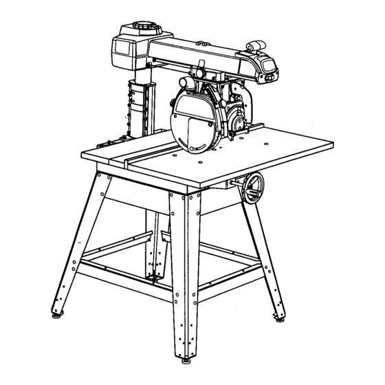
10 in. Stationary
RADIAL ARM SAW
Model No.
315.220380
Save this manual for
future reference.
CAUTION:
Read and follow all
Safety Rules and Operating
Instructions before first use of this
product.
Customer Help Line: 1-800-932-3188
Sears, Roebuck and Co., Hoffman Estates, IL 60179 LISA
visit the Craftsman web page: www.sears.com/craftsman
972000-505
3-99
• Safety
• Features
• Assembly
• Operation
• Maintenance
• Parts List
®
Advertisement
Table of Contents

Related Manuals for Craftsman 315.220380


Summary of Contents for Craftsman 315.220380
- Page 1 Safety Rules and Operating • Assembly Instructions before first use of this • Operation product. • Maintenance Customer Help Line: 1-800-932-3188 • Parts List ® Sears, Roebuck and Co., Hoffman Estates, IL 60179 LISA visit the Craftsman web page: www.sears.com/craftsman 972000-505 3-99...
- Page 2 FULL ONE YEAR WARRANTY ON CRAFTSMAN RADIAL ARM SAW If this CItRFTSMRN'Radial Arm Saw fails,dueto a defect in material or workmanshipwithin one year from the date of purchase, Sears will repair it, free of charge. Contact a Sears Service Center for repair.' If this product is used for commercial'orrental purposes, this warrantyapplies only for 90 days from the date of purchase.
- Page 3 AttachingElevating Handwheel ........................Installingthe Yoke Assembly......................... Removing the Blade............................AttachingTable Supports ..........................Setting the Arm Lock Knob ..........................Setting the Yoke Clamp ..........................Setting the Bevel Lock Lever ......................... Tightening the Arm and Column........................Adjustingthe Column Tube ........................28-29 Adjustingthe Carriage Bearings........................Levelingthe Table Supports..........................
- Page 4 The purpose of safety symbols is to attract your attention to possible dangers. The safety symbols, and the explanations with them, deserve your careful attention and understanding. The safety warnings do not by themselves eliminate any danger. The Instructions or warnings they give ere not substitutes for proper accident prevention measures.
-
Page 5: Electrical
When servicing,use only identical • REMOVE WRENCHES AND ADJUSTING KEYS. Craftsman replacement parts. Use of any other Get in the habit of checking - before turning on the parts may create a hazard or damage product. tool - that hex keys and adjusting wrenchesare removed from tool. - Page 6 • GUARD AGAINST KICKBACK, Kickbackcan ALLOW THE MOTOR TO COME UP TO FULL occur when the blade stalls, drivingthe work piece SPEED before starting a cut to avoid blade binding or stalling. back toward the operator. It can cause your hand to contact the blade, resultingin serious personal ALWAYS PUSH THE WORKPIECE when ripping;...
- Page 7 • BEFORE CUTTING, positionand tighten the blade M SECURE THE SAW. Firmly boltthe saw to the leg guard and anti-kickback pawls.Test the pawls to stand to keep the saw from tipping,walking, or make sure they would stop kickbackif it started. sliding.
-
Page 8: Extension Cords
ELECTRICAL CONNECTION Your Sears Craftsman Radial Arm Saw is powered by a precisionbuilt electric motor. It shouldbe connected to a power supply that Is 120 volts, 60 Hz, AC only (normal household current). It should be connected to a 240 volt power supply only If It has been reset according to the Instructions in this manual. -
Page 9: Changing Voltage
LIFTMOTOR COVER TOEXPOSE SWITCH CHANGING VOLTAGE See Figures 2-4. Your radial saw has been set up at the factoryto operate efficientlyon a 120V AC single voltagecircuit. However, if heavy duty operation is required,the circuitsare overloaded, or the circuitis low voltage, have a qualified electdcian change the voltage on the main power system to a 240V AC voltage circuit. - Page 10 Blade Arbor 5/8 in. 16 in. Cutting Capacity - Maximum In-Rip Blade Diameter 10 in. 3 in. Depth of Cut at 90" Depth of Cut at 45" 2.25 in. Blade Bevel Angle 0" - 90" Table Size 40 x 27.75 x 1 in. Radial Arm Swing Range 50"...
- Page 11 Throw-Back Resin Saw throwing back a workpiece similar to kickback. A sticky, sap-based substance. Through Sawing Rip Cut " In a radial saw, a cut made with the blade parallel to AnyCutting operation where the blade extends completely through the workpieca. the fence and perpendicularto the arm.
- Page 12 Check a ll loose parts from the box with the list below. Use the instructions on the followingpages to assemble. Allfasteners are shown actual size. Saw Assembly............ 1 SAWASSEMBLY SHOWN ASPACKED Fig. 5 3; Blade Wrench ..;.......... 2 Elevating Handwheel A.
- Page 13 Check a ll loose parts from the box with the list below. Use the Instructions on the followingpages to assemble. All fasteners are shown actual size. Fence ..............1 Saw Base To Leg Stand Assembly A. Saw Assembly(not shown) ......1 B.
- Page 14 Check all loose parts from the box with the list below. Use the instructions on the followingpages to assemble. All fasteners are shownactual size. 15. Leg Stand ............1 12. Table Support A. Leg ..............4 A. Table SupportRails ........2 B.
- Page 15 Thefollowing toolsareneeded f orassembly andalignment. They arenotincluded w iththissaw. LEVEL HEXKEYS: MEDIUM FLAT BLADESCREWDRIVER S/32In.AND1/8in. #2 PHILUPS SCREWDRIVER PENCIL SMALL HAMMER FRAMINGSQUARE Fig. 7 ClUlFt'$M AI1"RADIAL SAW315.220380...
- Page 16 -ontrol CutSettings Crospcut Wood Seftlng Feet Type Position Minute Hard Medium 0-20 Soft 0-35 B ,vel Cr0sscJt Wood Setting Feet Type Position Minute All Types Wood I Setting Feet Type [ Position Minute Hard 0-20 Mediuml 0-35 Soft Compound C r0= scot Wood i Setting Feet...
- Page 17 Control Cu_t On I Ofre & WARNING i_._,. ADVERTENClA F_pw sahd,/, read 0Nm maual b eta.op_'_q J" "War_ hqOlu. • Donotpedormfreehandeots. • Returncankiga tofull rear psaltisaalter eachcrossrut, :rr'.e'ock • SeeInotn_lonsoll hawtoreduce the riskM M_. "men dpplng,use pus_ rosa blade _ sot2 Inchesor moreDin _nu.
- Page 18 (motor, blade, and blade guard) and can be pivoted with all operating features and safety requirementsof so the blade faces right,front, or left. The motorcan your Sears Craftsman Radial Arm Saw. be rotatedto change the blade angle. *Shown on following pages...
-
Page 19: Features List
FEATURES LIST BEVEL LOCK LEVER - Sets and locks blade angle. It is located below the handle. See Figure 9B. See Figures 9A-9D. BLADE - For maximum performance, use the Crafts- ADJUSTABLE TABLES - A narrow spacer table and man 40-tooth, 10 in. carbide-tipped blade provided wider rear table that can be repositionedor even with your saw. - Page 20 CARRIAGE - Shdes a long track under a rm DUAL VOLTAGE - If needed, your main power source may be rewired by a qualified electdcianto supportsyoke. Contained in two carriage covers, one on each side of the arm. See Figure 9C. providea 240V AC circuit.
- Page 21 SWITCH TRIGGER - Used to power the controlcut MOTOR ( 13/6.5 AMP) - Powers t heblade andis device to allow yoke assembly to be pulledforward. controlled bytheswitch and key at the frontof the Mounted in the handle. See Figure 9D. arm.
-
Page 22: Loose Parts List
Assembly is best done in the area where the saw will • Place a 3/8-16 hex nut on each levelingfoot and be used. When you remove the saw and hardware insert levelingfeet intothe bottom of the legs. Cap from the packing matedals, carefullycheck the items with remaining3/8-16 hex nuts but only finger with the Loose Parts list. - Page 23 An'ACHING ELEVATING HANDWHEEL MOUNTING SAW TO LEG STAND See Figure 12. See Figure 11. _1= WARNING: Be sure the main power cord of WARNING: Firmly bolt the saw to the leg stand your saw is unplugged.Ignodngthis precaution to keep the saw from tipping,walking,or sliding. could resultin serious injury.
- Page 24 FORCLARITY, CARRIAGE COVERS ANDCARRIAGE LOCK INSTALLING THE YOKE ASSEMBLY KNOB ARENOTSHOWN IN ILLUSTRATION See Figures 13A - 13C. The yoke rides in the carriage below the arm and ARMLOCKKNOB supportsthe motor, the blade guard, and the blade. Install the yoke assembly from the front of the arm. BEARINGS ( 4) •...
- Page 25 ATTACHING TABLE SUPPORTS REMOVING THE BLADE See Figure 15. See Figure 14. Remove the blade and blade guard assembly during The table supportsare a base for the three wooden table sectionsand fence. setup for safety and better access. The blade guard includesan upper blade guard, an outer lower guard, •...
- Page 26 SET'rING THE ARM LOCK KNOB ARMCAP MOTOR See Figure 16. It may be possibleto move the arm when locked, if the arm lock knob is too loose• If the arm does not YOKELOCK move freely when unlocked,the arm lock knob may HANDLE be too tight.
- Page 27 SETTING THE REVEL LOCK LEVER See Figures 18A-18C, The bevel lock lever locksthe blade at desired angles other than the preset positivestop angles. The bevel lock lever is preset at the factory but may need readjustmentafter shippingor extended use. Check for overtightnessor looseness and make any neces- sary adjustmentsas follows: The bevel lock lever is locatedon the frontof the yoke...
- Page 28 TIGHTENING ARM AND COLUMN ADJUSTING THE COLUMN TUBE See Figure 19. See Figures 20A - 20D. There should be no play, vertical or horizontal,in the The purpos¢.pfthis procedureis to check whether the arm relativeto the column. If you can movethe arm inner column tube is snug in the housingand to remove any looseness.
- Page 29 ElevationAdjustment • Rotationcheck:To check the rotation, hold the front of the ann with one hand and grasp the top of the column supportwith the other. Press the arm to the side. If there is play between the column support and the column tube, it needs to be adjusted. See Figure 20B.
- Page 30 • Use a 9/16 in. wrenchto hold the eccentricscrew ADJUSTING THE CARRIAGE BEARINGS (top of beadng) and a 1/2 in. wrench to loosen the See Figures21A and 215. nut belowthe bearing. Loose carriage bearings permitthe blade to wander • Turn the eccentricscrew a partialturn as needed to slightlywhile cutting,which will resultin a poor cut tightenthe bearing.
- Page 31 LEVELING THE TABLE SUPPORTS Place the wrench belowthe shaft and checkthat the clearance is the same. If not, adjustthe table See Figures 22,4 and 22B. supportuntil it is the same, Securelytightenthe The table supports must be perfectlylevel. frontscrew, • Pull the bevel lock lever forward to unlockit. Use •...
- Page 32 INSTALLING THE FRONT TABLE U-CLIP AUGNU-CLIP OVER THISHOLE See Figures 23,4 - 23C. Use this procedure to installthe fixed fronttable. The top of the table has counterboredholes, preddlled from the top, around the center to attach the table. In the center are a counterbored hole and a small hole, which is not counterbored.They are used for raising or loweringthe center of the table until it is level.
- Page 33 LEVELING THE FRONTTABLE INSTALLING REAR TABLE, SPACER See Figure24. TABLE, FENCE, AND CLAMPS See Figures25A - 25C. If there are any high or low areas on the front table, they should be removed by adjustingthe leveling The placement of the tables and fence may need to screws in the center holes on the front table.
- Page 34 INSTALLING BLADE AND BLADE GUARD See Figures26,4 and 26B. • Collect the blade and hardware that were removed THUMBSCREW eadier. Place the inner bladewasher, saw blade, outer blade washer, and blade nut on the blade arbor. See Figure26A. Note: The concave side of blade washers go againstthe blade.
- Page 35 ALIGN RIVING KNIFE TO BLADE • With the elevating handwheel, lowerthe arm until the blade just clears the table. See Figures 27A - 27C. • Supportthe lower outer blade guard and loosenthe When rippingthe rivingknife must be cantered with carriage lock knobon the left of the arm. Move the the blade to ride in the middle of the kerf and keep it yoke back untilthe blade touchesthe fence.
- Page 36 INSTALLING RIP SCALE INDICATORS SCREWS See Figure 28. RIPSCALE INDICATOR The ripscale indicatorson the arm show the distance SPEEDNUT between the blade and the ripfence with the fence in the front and rear positions.The upper scale is used CARRIAGE when the fence is positioneddirectly behindthe front table.
- Page 37 Release the arm lock knob. Positionthe arm ALIGNING THE ARM FOR CROSS CUTS straightforward (O') and leave it unlocked. See Figures 29A - 29C. Lowerthe arm with the elevatinghandwheel until This procedure checks whether the arm is exactly O" the saw bladejust clears the front table. Lockthe for cross cut travel by checking the blade against the table and the miter indicator.Remove the rear table, yoke lock handle (rightside of saw, belowyoke)
- Page 38 ALIGNING BLADE TO TABLE AT O" BEVEL • If there are no gaps, fullytighteneach screw, If there is stilla gap, repeat the previoustwo steps. See Figures 30A - 30D. • Check the bevel indicatoron the yoke assembly This procedure squares the blade to the table at O" near the handle.
- Page 39 SQUARINGBLADE TO FENCE • Release the yoke lock handle (below the yoke on the fight). With a 1/2 in. wrench, slightlyloosen the See Figures 31A - 31C. two hex bolts holdingthe yoke pivotlatch. This procedure squares the miter angle of the blade to •...
- Page 40 PARALLELING BLADE TO TABLE • Check whetherthe blade is flat againstthe edge the entire length or whethera gap is visible. If you See Figures 32A-32C. can see a gap, adjustthe blade to be at 90" bevel This procedure squares the blade to the table at 90" to the table with the followingsteps.
- Page 41 ALIGNING THE RIP SCAL• INDICATORS • On the rightside of the arm, check the lower in-dp scale indicator,whichshould be set on O inches. If See Figures 33A - 33B. it is not, loosenthe screws and shift the indicator The rip scale indicatorson the arm show the distance untilit reads zero.
-
Page 42: Labels
INSTALLING CONTROL DEVICE • Plug in the control cut cord, leaving the main power See Figure 34. cord disconnected.Squeeze the switchtdgger to confirmthe control cut motoris receivingpower. Note: Before installingthe controlcut device, the yoke assembly will travel beck and forward on the •... - Page 43 RIP CUTS BASIC OPERATION OF THE RADIAL ARM SAW In dp cuts, the yoke is rotated 90" left or rightand locked in place. The wood must ride firmlyagainst the A radial arm saw can be used for straight-linecutting rip fence. There are two orientationsof ripcuts - the operations such as cross cutting,ripping, mitering, in-rip and the out-rip.
-
Page 44: Avoiding Kickback
SWITCH AND SWITCH See Figures 36-38. The main power switch has been placed on the front of the arm for easy access. The yellowswitch key prevents accidental startingof the main power switch when saw is not being used. To activate the switch, insertthe switch key and liftswitch to ON position.To lookthe switchonce it has been pressed to OFF, remove the yellow key. - Page 45 CUTTING AIDS See Figures 39-41. Cuttingaids are used to improve the setup and help make the operator's work safer end more accurate. They can be made from scrap wood and in various sizes and shapes for specific projects, The basic types are pushsticks,pushblocks,and featherboards.
- Page 46 MAKING A CROSS • If the blade is angled, raise the plasticlower guard, release the bevel lock lever, and set the bevel See Figure 42. indicatorto zero. Retightenthe bevel lock lever. Use this procedure to make a cut with the blade •...
-
Page 47: Making A Miter Cut
If the blade is angled, raise the plasticlower guard, SWITCH release the bevel lock lever, and set the bevel YOKELOCK indicatorto zero. Retightenthe bevel lock lever. CARRIAGE BLADE GUARD INDICATOR MITER CUT LOCKLEVER TABLE CLAMP ELEVATING HANDWHEEL Fig. 43 CRAFTSMAN" RADIAL S AW 315.220380... -
Page 48: Making A Bevel Cut
MAKING A BEVEL CUT • Release the switch triggerand let the carriage returnto the back, Turn the saw off with the switch See Figure 44. on the arm but hold the handle untilthe blade stops This procedure makes a cut with the blade and motor rotating.Adjustthe height with the elevating angled and the arm straight (90"... - Page 49 MAKING A COMPOUND CROSS CUI" • If the yoke is in front of the fence, loosen the carriage lookknobon the left side of the arm. See Figure 45. Release the switchtriggeron the handle and let the In this cut, boththe blade and the arm are angled. Be cardage retum to the back.
- Page 50 SETTING UP A RIP CUT RIP CUT HAZARDS AND PRECAUTIONS See Figure 46. Two hazards are specificallyassociated with rip cutting:ouffeed zone and wrong way feed. A precise and safe rip cut requiresa careful set up. Before setting up for in-rip or out-rip, especiallyfor a In the outfeed zone (behind the blade), the blade bevel cut, try the workpiece in both placements.
-
Page 51: Makinga Rip Cut
• Put the blade in the in-rippositionbetween the Keep your otherhand on the table and steady the • motorand the column.Release the yoke look workpieceagainst the fence. Keep that hand at least 8 in. from the blade. handle and pivotthe yoke to the left, with the yoke pivot latch on the right side of the arm. -
Page 52: Cutting Long Workpieces
MAKINGO_HER OUTS WARNING: Make sure the blade guard is See Figu_s 48 and 49, lowered and is workingproperlyto prevent possibleinjury. Variationsfrom the basic cuts includecuttinglong workpieces and non-throughcuts. WARNING: Never put your hands within 3 in. of When making one of the following cuts, followthe the blade when it is on. - Page 53 NON-THROUGH CUTS NON-THROUGH CUT See Figure 49. ,_L WARNING: Unplug the saw while removingor replacing the blade guard. Turn on the saw with the switch on the arm to confirmthe blade is not receivingpower. • Place a supportthe same height as the saw table nearby for the cut work.
-
Page 54: Maintenance
Frequentlyvacuum or blow out any sawdust from the work areas. WARNING: When servicing, use only identical Craftsman replacement parts. Use of any other part may create e hazard or cause product WARNING: If the power cords are wom, cut, or damage. - Page 55 PROBLEM CAUSE SOLUTION Saw does not start. I. Motor cord or control-cutcord is I. Plug in cord. not plugged in. 2. Have the cord or switch re- 2. Cord or switch is damaged. placed at your nearest Sears Service Center. 3.
-
Page 56: Setting The Yoke Clamp
PROBLEM CAUSE SOLUTION Saw vibmtas excessively. I. Blade is warped. 1, Replace the blade. See the removalprocedure in Assembly section, 2. Saw is not mounted securely, 2, Tighten all hardware. 3. Work surface is uneven. 3. Reposition on a flat surface. Adjust the leveling feet on legs. -
Page 57: Setting The Bevel Lock Lever
PROBLEM CAUSE SOLUTION Handwheel is hard to turn or I. Sawdust has collected on the I. Remove handwheel;clean end column binds, elevating shaft, lubricatethe shaft. 2, Columnis out of alignment. 2. See Adjustingthe Column Tube in Assemblysection. Saw burns or scores edges of 1. - Page 58 PROBLEM CAUSE SOLUTION Miter or cross cuts are not true, 1. Scale pointeris not correct. 1. Reset the pointerat the top rear of arm. 2. Column is out of alignment. 2. See Adjustingthe Column Tube in Assemblysection. 3. Carriage is misaligned. 3.
- Page 59 PROBLEM CAUSE SOLUTION Saw blade tends to push wood to 1. Blade is heeling. 1, See Squaring the Blade to the one side when cross cutting, Fence in Adjustmentssection, 2. Column tube is loose in column 2, See Adjustingthe Column support.
- Page 60 CRAFTSMAN RADIAL ARM SAW - MODEL NO, 315.220380 ARM SAW or when ordering repair parts. I The model number willbe found on a plate attachedto the base. Always mentionthe model number in all correspondence regardingyour RADIAL SEERGUREI 19 13 SEER...
- Page 61 CRAFTSMAN RADIAL ARM SAW - MODEL NO. 315.220380 ARM SAW or when ordering repair parts. be model numberwill be found on a plate attached to the base. Always mention the model number in all correspondenceregardingyour RADIAL PARTS LIST FOR FIGURE A...
- Page 62 CRAFTSMAN RADIAL ARM SAW- MODEL NO. 315.220380 The model number willbe found on a plate attached to the base. Always mention the modelnum- her in all correspondence regardingyour RADIAL ARM SAW or when ordering repair parts. SEE FIGL SEE FIGURE C FIGUREB I:RA FTSMRN"...
- Page 63 CRAFTSMAN RADIAL ARM SAW - MODEL NO. 315.220380 ber in all correspondence regardingyour RADIAL ARM SAW or when orderingrepair parts. The model number will be found on a plate attached to the base, Always mentionthe model num- PARTS LIST FOR FIGURE B...
- Page 64 CRAFTSMAN RADIAL ARM SAW - MODEL NO. 315.220380 ... iqHt rrr[[t Illll Illl iT he modelnumber willbe found on a plateattac/'_:l to_e base.Alwaysmention the modelnumber _naF_ c orrespondence r egarding yourRADIAL I ARM SAW °r when°rderin9repair parts ..• rrrrlnl Iqqr ....
- Page 65 CRAFTSMAN RADIAL ARM SAW- MODEL NO. 315.220380 ARM SAW or when orderingrepair parts. I The model number willbe found on a plate attached to the base. Always mentionthe model number in all correspondenceregardingyour RADIAL PARTS LIST FOR FIGURE C PART...
- Page 66 CRAFTSMAN RADIAL ARM SAW- MODEL NO. 315.220380 nu--w 0efouo on , o--0 on ooo0o • ber in all correspondence regardingyour RADIAL ARM SAW or when orderingrepair pads. RGURE D CRRFTSMRN" RADIAL S AW 315.220380...
- Page 67 Retaining Ring ................1 " STD571450 * Lock Nut (1/2-13) ................1 976298-001 Bevel Gear ..................1 976297-001 Bearing ..................2 * Standard Hardware Item -- May Be Purchased Locally ** Available From Div. 98 -- Source 980.00 CRAFTSMAN"RADIAL SAW315.220380...
- Page 68 CRAFTSMAN RADIAL ARM SAW - MODEL NO. 315.220380 bar in all correspondenceregardingyour RADIAL ARM SAW or when ordering repair parts. The model numberwill be found on a plate attached to the base. Always mention the model num- FIGURE E £RAFTSMAN" RADIAL SAW 315,220380...
- Page 69 CRAFTSMAN RADIAL ARM SAW- MODEL NO. 315.220380 The model number will be found on a plate attached to the base. Always mention the model num- ber in all correspondence regardingyour RADIAL ARM SAW or when orderingrepair parts. PARTS LIST FOR FIGURE E...
-
Page 70: Radial Arm Saw
CRAFTSMAN RADIAL ARM SAW- MODEL NO. 315.220380 The model number will be found on a plata attached to the base. Always mention the model num- bet in all correspondenceregardingyour RADIAL ARM SAW or when orderingrepair pads. _ 21 SEE FIGURE G FIGUREF CRRFTSNRN"RADIALSAW315.220380... - Page 71 CRAFTSMAN RADIAL ARM SAW - MODEL NO, 315.220380 The model number will be found on a plate attached to the base. Always mentionthe model nurn- ber in all correspondence regardingyour RAOIAL ARM SAW or when ordedng repair parts. PARTS LIST FOR FIGURE F...
- Page 72 CRAFTSMAN RADIAL ARM SAW - MODEL NO. 315.220380 The model number will be found on a plate attached to the base. Always mentionthe model num- ber in all correspondence regardin 9 your RADIAL ARM SAW or when ordering repair parts.
- Page 73 CRAFTSMAN RADIAL ARM SAW - MODEL NO. 315.220380 The model number willbe found on a plate attached to the base. Always mention the model num- ber in all correspondence regardingyour RADIAL ARM SAW or when orderingrepair parts. PARTS LIST FOR FIGURE G...
- Page 74 CRAFTSMAN RADIAL ARM SAW- MODEL NO. 315.220380 ARM SAW or when orderingrepair parts. I The model number will be found on a plate attached to the base. Always mentionthe model number in all correspondenceregardingyour RADIAL FIGURE H...
- Page 75 CRAFTSMANRADIALARM SAW- MODELNO.315.220380 ARM SAW or when ordering repair parts. The model numberwill be foundon a plate attached to the base. Always mentionthe model number in all correspondenceregardingyour RADIAL PARTS LIST FOR FIGURE H PART NUMBER DESCRIPTION QUAN. 610122-006 * Screw (6-32 x 5/8 in.Pan Hd.).......................... 976449-001 Handle Assembly...
- Page 76 CRAFTSMAN RADIAL ARM SAW- MODEL NO. 315.220380 ARM SAW or when ordering repair parts. The model numberwill be foundon a plate attached to the base, Always mention the model number in all correspondenceregardingyour RADIAL €O FIGUREI...
- Page 77 CRAFTSMANRADIALARM SAW- MODELNO. 315.220380 ARM SAW or when orderingrepair parts. The model numberwill be found on a plate attached to the base. Always mentionthe modelnumber in all correspondenceregardingyour RADIAL PARTS LIST FOR FIGURE I PART PART NUMBER DESCRIPTION QUAN. NUMBER DESCRIPTION QUAN.
- Page 78 CRAFTSMAN RADIAL ARM SAW - MODEL NO. 315.220380 ARM SAW or when orderingrepair parts. I The model number willbe found on a plate attached to the base. Always mentionthe model number in all correspondenceregardingyour RADIAL SEERGUREK RGUREJ...
- Page 79 CRAFTSMANRADIALARM SAW- MODELNO.315.220380 ARM SAW or when orderingrepair parts. I The model numberwill be found on a plate attached to the base. Always mentionthe model number in all correspondenceregardingyour RADIAL PARTS LIST FOR FIGURE J PART NUMBER DESCRIPTION QUAN. 607818-002 Sleeve Beadng ..............................
- Page 80 CRAFTSMAN RADIAL ARM SAW - MODEL NO. 315.220380 ARM SAW or when orderingrepair parts. I The model number willbe found on a plate attached to the base. Always mention the model number in all correspondenceregardingyour RADIAL I" RGUREK...
- Page 81 CRAFTSMANRADIALARM SAW- MODELNO.315.220380 ARM SAW or when ordering repair parts. The model number will be found on a plate attached to the base. Always mention the model number in all correspondenceregarding your RADIAL PARTS LIST FOR FIGURE K PART NUMBER DESCRIPTION QUAN.
-
Page 82: Maintenance
For in-home major brand repair service: Call 24 hours a day, 7 days a week 1-800-4-MY-HOME s" (1-800-469-4663) Para pedir servicio de reparacibn a domicilio - 1-800-676-5811 In Canada for all your service and parts needs call - 1-800-665-4455 Au Canada pour tout le service ou les pi_ces For the repair or replacement parts you need: Call 6 am - 11 pm CST, 7 days a week...
Need help?
Do you have a question about the 315.220380 and is the answer not in the manual?
Questions and answers