Craftsman 247.770990 Operator's Manual
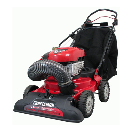
6.5 horse power power propelled yard vacuum
Hide thumbs
Also See for 247.770990:
- Operator's manual (56 pages) ,
- Parts list (9 pages) ,
- Operator's manual (33 pages)
Advertisement
Available languages
Available languages
Quick Links
Operator's
Manual
I:RRFTSMRN +
6.5 Horse Power
POWER PROPELLED YARD VACUUM
Model No. 247.770990
CAUTION:
Before
using
this product,
read this
manual
and follow
all
safety
rules
and operating
instructions.
+ SAFETY
• ASSEMBLY
+ OPERATION
+ MAINTENANCE
+ PARTS LIST
ESPAI_OL
Sears, Roebuck and Co., Hoffman
Estates,
IL 60179, U.S.A.
Visit our web site: www.sears.com/craftsman
FORMNO. 769-01281B
06/27/2006
Advertisement

Subscribe to Our Youtube Channel
Related Manuals for Craftsman 247.770990


Summary of Contents for Craftsman 247.770990
- Page 1 + OPERATION + MAINTENANCE CAUTION: Before using + PARTS LIST this product, read this manual and follow ESPAI_OL safety rules and operating instructions. Sears, Roebuck and Co., Hoffman Estates, IL 60179, U.S.A. Visit our web site: www.sears.com/craftsman FORMNO. 769-01281B 06/27/2006...
- Page 2 BackCover Service AndAdjustment ......Page16-19 OneYearFull Warranty on Craftsman YardVacuum This equipmentis coveredbya one-yearwarranty,providedthat it is maintained, l ubricated,and tunedup accordingto the instructionsin the operator'smanual.Duringthe warrantyyear,if this equipmentexperiencesany failuredue to defects in materialor workmanship,RETURNIT TO YOURNEARESTSEARSPARTS& REPAIRCENTER,and Searswill repairit, freeof charge.In-homewarrantyserviceis available,butyou will haveto paya trip charge.
- Page 3 Congratulations onmaking asmart purchase. Your new Craftsman® Purchase a Repair Protection Agreement now and protect yourself product isdesigned and manufactured foryears ofdependable opera- from unexpected hassle and expense. tion. But l ike allproducts, itmay r equire repair from time totime. That's...
- Page 4 chemicals known to State of California to cause cancer and birth defects or other reproductiveharm. WARNING: Engine Exhaust, some of its constituents,and certain vehicle components contain or emit DANGER: This machine was built to be operated according to the rules for safe operation in this manual. As with any type of power equipment, carelessness or error on the part of the operator can result in serious injury.
- Page 5 Operation Maintenance & Storage 1. Do not put hands andfeet near rotatingparts or inthe feedingchambers 1. Nevertamperwith safetydevices.Checktheir properoperationregularly. and dischargeopening.Contactwiththe rotatingimpellercan amputate 2. Check bolts andscrewsfor proper tightnessat frequentintervalsto keep fingers,hands,andfeet. the machinein safe workingcondition.Also, visuallyinspectmachinefor 2. Beforestartingthe machine,makesurethe chipperchute,feed intake,and any damageand repair,if needed.
- Page 6 _Upper Handle IMPORTANT: This unitis shippedwithoutgasolineor oil in the engine. Be certainto serviceenginewith gasolineand oil as instructedin the separateenginemanualbeforeoperatingyourmachine. Drive Control.,,,,,,,_ _eed Control Wing Nut NOTE:Referenceto rightand left handside of the YardVacuumis Upper Hose Handle observedfromthe operatingposition. Cable Guide RopeGuide j/_ OPENING CARTON 1.
-
Page 7: Attaching The Handle
ATTACHING THE HANDLE 1. Removethehairpinclips fromthehandlebracketsand removethe Carriage Screw carriagescrewsand wingnuts fromthelowerhandle. a. Placethe bottomholesin lowerhandleoverthe pins on the Wing handlebracketsand securewith hairpinclips. See Figure2. b. Insertcarriagescrewsthroughupper hole in lowerhandlefrom the insideand securewith wing nuts.See Figure2. 2. a. Unfoldthe upperhandleuntilit alignswith lowerhandle.Make sure the ropeguide is on the rightsideof upperhandle.See Figure3. - Page 8 6. a. Snapthe hosehandlefirst intothe upper hosehandlebracket Upper and then intothe lowerhosehandle bracket. b. Layhosetubingon hangerbracketnextto chipperchute.See Figure6. Bracket ATTACHING THE BAG 7. Graspbag handlewith one handand slide lockingrod on mounting bracketwith otherhandtowardengine.Usethe end of mounting Hose bracketas leveragewhenslidingthe lockingrod. Lower Hose a.
- Page 9 ATTACHING THE BLOWER CHUTE NOTE:The bag mustbe removedbeforeinstallingthe blowerchute. 8. a. Graspblowerchute with one handand slide lockingrod on mountingbracketwith other handtowardengine.Use the end of mountingbracketas leveragewhenslidingthe lockingrod. See Figure8. b. Slip blowerchute overrim of dischargeopeningand release lockingrod to secure chutein place,as in Figure8. c.
- Page 10 Drive Control Speed Control Starter Handle Throttle Control Choke Control Bag Handle Fill Fill Hose Handle Hose ,,_Assembly Chipl Nozzle/Hose Blower Chute Nozzle NozzleHeig Adjustment Lever Figure 9 Now that youhaveset up youryardvacuumfor operation,get Speed Control acquainted with its controlsand features. T hese are describedbelow Locatedon the left sideof the upperhandle,the speedcontrolis used and illustratedon this page.This knowledgewill allowyouto use your to selectthe forwardspeedof the yardvacuum.
- Page 11 Choke Control 1. Checkthe oil levelmakingcertain notto rub the dipstickalongthe insidewalls of the oil fill tube.This wouldresultin a false dipstick The choke controlis usedto choke thecarburetorand assist in starting reading.Refillto FULL markon dipstick,if necessary.Capacity the engine. isapproximately18oz. Overfillingwill causethe engineto smoke Starter Handle profuselyand will result in poor engineperformance.
-
Page 12: To Stop Engine
TO STOP ENGINE 1. Move throttlecontrol leverto STOPor OFF position. ThrottleControl 2. Disconnectspark plugwire and groundit to the retainingpost to preventaccidentalstartingwhilethe equipmentis unattended. ChokeControl be careful of heatedsurfaces and sharp edgeson ARNING:When moving throttle controllever, muffler guard. TO START ENGINE 1. - Page 13 TO REMOVE BLOWER CHUTE Nozzle/Hose Hose 1. Graspblowerchute with one handand pull lock rod on mounting VacLever bracketwith otherhand towardengine to release.Referto Figure7. (Top Positi 2. Removeblowerchutefrom overthe rim of the dischargeopening. USING THE NOZZLE VACUUM 1. Placenozzle/hosevac leverin the top positionon the nozzleto vacuumthroughnozzle.See Figure13.
- Page 14 CLEAN EQUIPMENT 1. Cleanthe YardVacuumthoroughlyafter eachuse. 2. Wash bag periodically with water.Allowto dry thoroughlyin shade. 3. If the flail screenbecomesclogged,removeand cleanas instructed in the SERVICEAND ADJUSTMENTS section. NOTE:Cleaningwith a forcefulspray of wateris not recommended as it couldcontaminate the fuelsystem. CHECK ENGINE OIL 1.
-
Page 15: Service Spark Plug
--,, 2. Removepleatedfilter from plastichousingcoverand replacewith cleanor newfilter. 3. Tilt cover up into placeand tightenscrew. NOTE:If thefilter istorn or damagedin anyway,replaceit. may exceed 150 ° F (65°C). Avoidthese areas. ARNING:Temperature of muffler and nearbyareas SERVICE SPARK PLUG 1..030 (.76 turn) Gap 2. - Page 16 NozzleHeight to the unit withoutfirst stoppingengineand discon- Adjustment WARNING: Do not at any time make any adjustment nectingspark plug wire. NOZZLE HEIGHT ADJUSTMENT The nozzlecan be adjustedtoany six positions,rangingfrom5/8" to4 1/8"groundclearance.The nozzleheighthastobe adjustedaccording toyard conditions. 1. Depressnozzleheightadjustmentlevertowards wheel.See Figure 2. Move the heightadjustmentleverforwardor backwardto adjustthe nozzle upwardsor downwards.Makesureboth leversare in the same position.
-
Page 17: Carburetor Adjustment
CARBURETOR ADJUSTMENT Self Tapping made to the enginewhilethe engineis running, crews ARNING:if any adjustments (e.g. carburetor) are keepclear of all moving parts. Becarefulof heated surfacesand muffler. : ..Belt Cover The carburetorhas been pre-setat thefactory and shouldnot require adjustment.If yourenginedoes notoperateproperlydueto suspected /<... - Page 18 SHARPENING OR REPLACING Hex Cap .... " CHIPPER BLADE , Screws NOTE:Whentippingthe unit, emptythe oil and fuel tankand keep enginespark plug side up. 1. Disconnect and ground the spark plugwire to retaining post. 2. Removehoseassemblyand bag assembly. 3. Removethe threehexcap screwsholdingthe hosehangerbracket and chipperchuteto the upper housing.See Figure22.
- Page 19 --,, 7. Carefullytilt and supportthe unitup to provideaccessunderneath to the nozzlemountinghardwareand impeller.Removethe three shoulderbolts securingthe black plasticlowerflail housingto the lowerhousing.Referto Figure25. Black Plastic 8. Tilt top of black plasticlowerflailhousingtowardthe engineto remove. lower flail 9. Usinga 3/16"allen wrench,removethe flat head capscrewsthat housing hold thechipperblade to the impeller.
- Page 20 PrepareyourCraftsmanYardVacuumfor storageat the end of the ,, Do not drainthe gas tank and carburetorif usingfuel stabilizer. seasonor if the unitwill not be usedfor 30 daysor longer.A yearly Inall cases,drain all the oil fromthe crankcase(thisshouldbe done check-upbyyour localSearsParts & RepairCenteris a good wayto after the enginehas beenoperatedand is still warm)and refillthe ensurethat the unit runsproperlynextseason.
- Page 21 Problem Cause Remedy Enginefails start 1. Throttlelevernot in correctstartingposition• 1. Movethrottleleverto FASTor STARTposition. 2. Sparkplug wiredisconnected. 2. Connectwireto sparkplug. 3. Chokenot in ONposition. 3. MoveCHOKEto ONposition. 4. Fueltank emptyor stalefuel• 4. Filltank with clean,fresh gasoline• 5. Cannotpull recoilcord• 5. Obstructionlodgedin mpeller.D sconnect sparkplug wire and removelodgedobject, 6 Fault s ark lu 6 Cean adjustgap orrepace...
- Page 23 Craftsman 6.5 H. P. Yard Vacuum Model 247.770990 Ref.No. PartNo. Description Ref. No. Part No. Description 731-0981A HubCap 710-1650 ShoulderScrew,#12-24x .30 x .46 749-04163 UpperHandle 710-1220 Screw,#12-16 x .750 720-0279 Knob 711-04245 ImpellerHub 715-0221 DowelPin 710-1205 EyeBolt 781-1056 UpperHandleBracket 781-04082...
- Page 25 Craftsman 6.5 H. P. Yard Vacuum Model 247.770990 Ref.No. PartNo. Description Ref. No. Part No. Description 664-0094 BagAssembly 764-0631A 681-0154 ScreenAssembly 631-0083 ChuteAssembly 710-1054 HexScrew5/16-24x 1.0 736-0247 FlatWasher.375ID x 1.25OD 736-0217 LockWasher3/8 781-0490 ChipperBlade 781-0735 PinClip 710-1273 Hex CapScrew,3/8-24x 2.75...
- Page 26 Craftsman 6.5 H.P. Engine Model No. 123K02 For Yard Vacuum Model 247.770990 j 1019 LABEL Kl_ 525 i J 1330 REPAIR MANUAL i i1058 OWNER'S MANUAI.j 5O5 @...
- Page 27 Craftsman 6.5 H.P. Engine Model No. 123K02 For Yard Vacuum Model 247.770990 443_ 692 J 633A @ 977 CARBURETOR GASKET SET 33 ® 633A @ 276_ 276 _...
- Page 28 Craftsman 6.5 H.P. Engine Model No. 123K02 For Yard Vacuum Model 247.770990 __329 REPLACEMENT ENGINE i 627 _ 347 _ 969_ 497_ /_---_ 1005 1210 ..597 _ 1036 EMiSSiONS LABEL...
- Page 29 Craftsman 6.5 H.P. Engine Model No. 123K02 For Yard Vacuum Model 247.770990 Ref.No. PartNo. Description Ref. No. Part No. Description 697322 CylinderAssembly 697316 Rope-Starter(Cutto RequiredLength) 399269 Kit-Bushing/Seal 281434 Grip-StarterRope 299819t Seal-Oil(MagnetoSide) 690837 Screw(RewindStarter) 493279 Sump-Engine 691108 Screw(FlywheelGuard) 691740 Lock-MufflerScrew 691160...
- Page 30 Craftsman 6.5 H.P. Engine Model No. 123K02 For Yard Vacuum Model 247.770990 Ref. No. PartNo. Description Ref. No. Part No. Description 356. 496381 Wire-Stop 684. 690345 Screw (BreatherPassageCover) 358. 497316 EngineGasketSet 689. 691855 Spring-Friction 363. 19069 FlywheelPuller 692. 690579 Spring-Detent 365.
- Page 31 TO AVOID SERIOUS iNJURY . READ OPERATOR'S MANUAL , KEEP HANDS OUT OF INLET AND DISCHARGE OPENINGS WHEE MACHINE iS RUNNING. ROTATINGBLADESARE iNSiDE. TURN ENGINE OFF AND ALLOW iMPELLER TO COME TO COMPLETE STOP BEFORE REMOVING BAG. DO NOT ATTEMPTTO CLEARACLOG ORJAM WITH THE ENGINERUNNING. "...
- Page 32 (This pageapplicablein the U.S.A.and Canadaonly.) Sears, Roebuck and Co., U.S.A. (Sears), the California Air Resources Board (CARB) and the United States Environmental Protection Agency (U.S. EPA) Emission Control System Warranty Statement (Owner's Defect Warranty Rights and Obligations) EMISSIONCONTROL WARRANTYCOVERAGE ISAPPLICABLE TO CERTI- YEAR 1997AND LATERENGINES WHICHARE PURCHASED AND USED FlED ENGINESPURCHASEDIN CALIFORNIA IN 1995ANDTHEREAF- ELSEWHERE INTHE UNITEDSTATES (ANDAFTERJANUARY1,2001 IN...
- Page 33 Look For Relevant Emissions Durability Period and Air index information On Your Engine Emissions Label Engines that are certified to meet the California Air Resources Board (CARB) Tier 2 Emission Standards must display information regarding the Emissions Durability Period and the Air Index. Sears, Roebuck and Co., U.S.A. makes this information available to the consumer on our emission labels.
- Page 34 Manual dei operador I:RRFTSMRN ° 6.5 caballos de fuerza ASPIRADORA PARA PATIOS CON PROPULSION NOmero de modelo 247.770990 • SEGURIDAD MONTAJE OPERACION PRECAUCION: antes MANTENIMIENTO LISTADO DE PIEZAS utilizar este producto, ESPANOL este manual y siga todas reglas de seguridad y las instrucciones de operaci6n.
- Page 35 Declaraci6n de garantia ...... PAgina 2 Mantenimiento ........PAginas 14-15 Acuerdo de Protecci6n Para Servicio y ajuste ........ PAginas 16-19 Reparaciones ........PAgina 3 Almacenamiento fuera de temporada..PAgina 20 PrActicas operaci6n seguras ....PAginas 4-5 Soluci6n de problemas ...... PAgina 21 Montaje ..........
- Page 36 Felicitaciones por haberrealizadouna adquisici6ninteligente.El tecnicode Searspara los productosque requierenreparaci6n productoCraftsman@ que ha adquiridoest,. disehadoy fabricado a domicilio,adem_ts de una programaci6n convenientepara la parabrindar muchosahosde funcionamiento confiable.Perocomo reparaci6n todos losproductosa vecespuederequerirde reparaciones. E sen Unavez adquiridoel Acuerdo,puede programarel serviciocon ese momentocuandoel disponerde un Acuerdode protecci6npara tan s61orealizaruna Ilamadatelef6nica.Puede Ilamaren cualquier reparaciones le puedeahorrardineroy problemas.
- Page 37 ponentes d elvehiculo c ontbnen o erniten productos quirnicos q ueelestado deCalifornia c onsidera q ue ADVERTENCIA: elescape delmotor d eesteproducto, algunos d esuscornponentes y algunos c orn- pueden producir cancer, defectos d enacirniento u otros problemas r eproductivos. PELIGRO: estarn_.quina est,.diseSada p araserutilizada respetando lasreglas deseguridad c ontenidas enestemanual. AIigual q ueconcualquier tipodeequipo electrico, undescuido o errorpotpartedeloperador puede producir lesiones graves.
- Page 38 Operaci6n Mantenimiento y almacenamiento 1. No pongalasmanos o los piescerca de las piezas rotatoriaso en las 1. Nuncamanipulelosdispositivosde seguridadde manera imprudente. camarasde alimentaci6nni en laabertura de descarga. El contactocon el Controleperi6dicamente que funcionende formaadecuada. motorrotatoriopuedeproducirla amputaci6nde dedos, manoso pies. 2. Controlefrecuentementequetodos los pernosy tornillosesten bien 2.
- Page 39 IMPORTANTE: E sta unidadse enviasin gasolinani aceiteen el mo- Manija superior _, tor. Antesde operarla m_.quina cargueel motorcon gasolinay aceite Control delatransmisi6n como se indicaen el manualseparadodel mismo. Control de velocidad NOTA:Las referenciasa los ladosderechoe izquierdode la aspira- Sopor_e paralamanija de dora para patiosse hacenobservandola maquinadesdela posicidn la manguera superior Guia delcable...
- Page 40 IVIONTAJE DE LA MANIJA 1. Saquelosbroehes de horquilla de lossoportesde lamanija,y saque Tornillo del carro lostornillos d el oarroy lastueroas d e mariposa de lamanijainferior. Tuercade a. SittJelos agujerosinferioresde la manijainferiorsobrelos mariposa pernosde lossoportesde la manija,y asegOrelos conbrochesde horquilla.Vea la figura2. b.
- Page 41 6. a. Primero,una a presidnla manijade la mangueraconel soporte parala manijade la manguerasuperior,y despuescon el soporte de la manguerainferior. b. Sit0eel cahode la mangueraen el ganchode soportejuntoal canalde la cortadora.Veala figura6. MONTAJE DE LA BOLSA 7. Sostengala manijade la bolsacon una manoy deslice la varillade seguridaddel soportede montajehaciael motorconla otra mano.
- Page 42 iNSTALAR EL CANAL DE SOPLADO NOTA:hayque retirarla bolsaantes de instalarel canalde soplado. Canalde oplado 8. a. Tomeel canalde sopladocon una manoy deslice la varillade seguridaddel soportede montajehaciael motorcon la otra mano.Use el extremodel soportede montajecomo palanca cuandodeslice la varillade seguridad. V ea la figura 8. b.
- Page 43 Arranque / lento / Motor apagado para engranarlas ruedas,y sueltelopara desengranarlas. ( NOsuelte funcionamiento marcha lenta el embrague. Cumple con los est_indares de seguridad de ANSI Lasaspiradoras p arapatiosde Craftsman cumplen conlosest_ndares de seguridad delinstituto estadounidense d e est_.ndares nacionales (ANSI).
- Page 44 Control de obturaci6n 1. Compruebeel nivelde aceite asegur_.ndose q ue la varilladel nivel de aceiteno rocecon las paredesinterioresdel tubo de Ilenado El control de obturaci6nse utilizapara cebarel carburadory ayudara de aceite.Dehacerlose puede produciruna lecturafalsa de la _e el motorarranque. varilladel nivelde aceite.Rellenehasta la marcade FULL (lleno) anija del arrancador de la varilladel nivelde aceite,si es necesario.La capacidades de Se utiliza paraencenderel motor.
- Page 45 PARA DETENER EL MOTOR 1. Mueva laspalancasde controldel reguladora la posici6nSTOP (detenci6n)u OFF (apagado). Control d elestrangulador 2. Desconecteel cablede la bujiade la bujia y col6queloa masa contra el poste de retenci6nparaevitar que se enciendaacciden- ControldeobturaciOn talmentemientrasno se est,.prestandoatenci6nal equipo. ADVERTENClA: C uando mueva la palancadel ciescalientesy los hordes afilados de la protecci6n controldel regulador tenga cuidadocon lassuperfi-...
- Page 46 EXTRACCION DEL CANAL DE P'_alanca del pico / Adaptador de SOPLADO manguera de la la man( 1. Tomeel canalde sopladocon una manoy tire de la varillade aspiradora (po,, seguridaddel soportede montajehaciael motorcon la otra mano superior) para soltarlo.Consultela figura7. 2. Saqueelcanaldesopladoporencimadelbordedelaaberturadedescarga. USO DEL PICO DE LA ASPIRADORA 1.
- Page 47 LIMPIEZA DEL EQUJPO 1. Limpiecuidadosamente la aspiradorapara patiosdespuesde cada USO. 2. Lave la bolsacon aguaperi6dicamente. P ermitaque se sequebien en un sitio a la sombra. 3. Si se tapa la pantallade desgranado, s _.quela y limpielacomo se indicaen la secci6nSERVlCIOY AJUSTES. NOTA:la limpiezacon un chorrode aguaa presi6nno se recomienda, ya que el sistemade combustiblepodria resultarcontaminado.
-
Page 48: Limpieza Del Motor
--,, SERVlCIO DEL FILTRO DE AIRE El filtro de aire evitael ingresoal carburadorde suciedad,polvo,etc. perjudiciales y evitaque los mismosseanintroducidosdentrodel mo- tor. Adem_.s, dicho filtroes importantepara la vida Otily el rendimiento del motor.El filtro de aire constade un filtro plisado.No ponganunca en funcionamiento el motorsin habermontadototalmenteel filtro de aire. - Page 49 Palancade ADVERTENCIA: bajo ninguna circunstancia realice ning_ntipo deajustea la unidad sin detenerel motor ajuste de la y desconectar elcablede la bujia con anterioridad. AJUSTE DE LA ALTURA DEL PICO Puedeajustarel pico en seis posicionesque variandesde5/8" a 4 1/8"de distanciadel suelo. Debeajustarla alturadel picosegOnlas condicionesdel patio.
-
Page 50: Ajuste Del Carburador
AJUSTE DEL CARBURADOR Tornillos autQrroscantes Cubierta el mismoest;_ en marcha(pot ejemplo, al carburador), de la DVERTENClA: si se realizanajustesal motor mientras al_jesede todas laspiezasm6viles.Tengacuidadocon co/rrea las superficies c alientesy conel silenciador. El carburadorse ha preconfigurado en la f_.brica, y no debe necesitar m_.sajustes.Si su motorno operaadecuadamente y se sospecha que es por culpadel carburador, I levesu aspiradorapara patiosa un centrode partesy reparaciones Searsparaque la repareny ajusten. - Page 51 AFILADO O REElVIPLAZO DE LAS Tornillos de cabeza HOJAS DE LA CORTADORA hexagonal NOTA:cuandoinclinela unidad,vade el dep6sitode combustibley ,/';: aceite,y mantengael lado de la bujfahaciaarriba. 1. Deeconecte el cablede la bujia y p6ngalode maneraque haga maea contra el poetede retenci6n. 2.
- Page 52 7. Inclinela unidadcon cuidadoy ap6yelahaciaarriba para obtener accesopor la parteinferioral materialde montajedel picoy al motor.Retirelos tres tornilloscon rebordeque aseguranel pico de pl_tstico negroa la caja inferior.Consultela figura25. 8. Inclinela partesuperiordel pico de pl_tstico negro haciael motor para retirarlo. 9. Medianteuna IlaveAllen de 3/16",retirelostornillosde cabeza negro planaque sujetanla hoja de la cortadoraal motor.Dichostornillos sonaccesiblesa travesde la aberturaque se cre6 cuandoretir6el...
- Page 53 Preparela aspiradorapara patiosCraftsmanpara su almacenamiento Entodos loscasos,dreneel aceite del c_.rter(Ioque deberia hacerse al finalizar la temporada,o si nova a utilizarla unidaddurante30 tras la operaci6ndel motor,mientraseste todaviacaliente)y relleneel carter con aceitenuevo. diaso m_ts. U n buenm_todopara asegurarque la unidadfuncione adecuadamente la siguientetemporadaes realizaruna inspecci6n anualpor partede su centro localde partesy reparacionesSears.
- Page 54 Problema Causa Remedio 1. La palancadel regJladorno ester en la oosicionde 1. k4ueva la 3alancade] regulaaora iaposici6nFAST El motor no arranca arranquecorrecta. (rApido)o STARTfinicioL 2. Se ha desconectadoel cable de la bujia, 2. Conecteel cable a la bulia. 3. La Daiancade obturacionno estAen la posici6nON 3.
- Page 55 TO AVOID SERIOUS iNJURY . READ OPERATOR'S MANUAL , KEEP HANDS OUT OF INLET AND DISCHARGE OPENINGS WHEE MACHINE iS RUNNING. ROTATINGBLADESARE iNSiDE. TURN ENGINE OFF AND ALLOW iMPELLER TO COME TO COMPLETE STOP BEFORE REMOVING BAG. DO NOT ATTEMPTTO CLEARACLOG ORJAM WITH THE ENGINERUNNING. "...
- Page 56 (Esta pagina se aplica s61oen EE.UU. y Canada). Sears, Roebuck and Co., U.S.A. (Sears), el Consejo de Recursos Ambientales de California (CARB) y la Agencia de Protecci6n Ambiental de los Estados Unidos (EPA) Declaration de garantia del sistema de control de emisiones (derechos y obligaciones de la garantia de defectos del propi- etario) LA COBERTURA DE LA GARANTfA DE CONTROLDE EMISIONESES...
Need help?
Do you have a question about the 247.770990 and is the answer not in the manual?
Questions and answers