All-Power APG3009 Owner's Manual
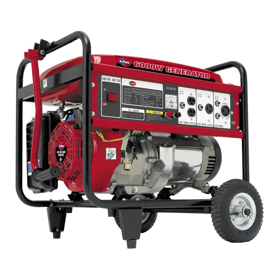
600 watt generator
Hide thumbs
Also See for APG3009:
- Owner's manual (34 pages) ,
- Owner's manual (34 pages) ,
- Owner's manual (34 pages)
Table of Contents
Advertisement
Advertisement
Table of Contents

Subscribe to Our Youtube Channel
Related Manuals for All-Power APG3009


Summary of Contents for All-Power APG3009
- Page 2 Tableof Contents Topic Page IMPORTANT SAFETY _NFORMATiON Carbon Monoxide Hazards Safety Guidelines - De_nitions General Precautions #_sembly Operation Usage Of Generator Pre-ope_ation Check Maintenance Compiian_ Limited Warrant:y WARNING! READ AND UNDERSTANDALL SAFETYPRECAUTIONSIN THISMANUAL BEFOREOPERATING,FAILURE TO COMPLYWITH INSTRUCTIONSIN THISMANUALCOULDRESULT IN PERSONAL INJURY, PROPERTY DAMAGE,AND/OR VOIDING OF YOUR WARRAN_ ALbP3WER USA WILL NOT BE LIABLE FOR ANY DAMAGE...
- Page 3 SAVE THESE INSTAUCTIONS- TNs manual important instructions APG3009that s hould be%0wed d uring installation and maintenance ofthegenerator and batteries. You will need tNs ma_a[ for the safety war_s and precauti_s, operating, inspection maintenance cleaning procedures, parts _ist and asse_[y _ag_'am_ Keep your invoice with this manual Write this invoice nuttier on the...
- Page 4 iMPORTANT SAFETY I TRUCTION (CON ) GENERATOR SAFETY I Do nat overload the gene_'alo_ Use the co,reel generator fo_ yo_ application The correct generato_;will do t_ job better and safer at lhe fate br which it is designed. 2 Do not expose to rain or 'wet conditions. Water entering a generator will ins[ea_ the risk of electric sh_K &...
- Page 5 IMPORTANT SAFETY INSTRUCTION (CONT,) CPSC Alert Portable Generator Hazards Carbon: Monoxide Hazards NEVER use a generator in enclosed or partially-enclosed spaces Generators can produce high levels of Carbon Monoxide very quickly. When you use a portable generator, remember that you cannot smeil or see Follow...
- Page 6 IMPORTAh_r SAFETY I_TRUCTION (CONT,) Safety Guidelines - Definitions information. Please read the manual and pay attention to these sections. WARNING! WARNINGSINDICATEA CERTAIN_ OR STRONG POSSIBILITY OF PERSONALINJURY OR DEATH IF INSTRUCTIONS ARE NOT FOLLOWED_ CAUTION: CAUTIONS INDICATE A POSSIBILI_ EQUIPMENT DAMAGE IF INSTRUCTIONS FOLLOWED,...
- Page 7 iMPORTANT SAFETY INSTRUCTION (CONT,) Carbon Monoxide When this tool is running_ ensure that the area is we{_ ventilatad_ Never run the engine in,an enclosed area Run the engine in an open area or wi_h an exhaust evacuation system in an enclosed area, WARNING! THE EXHAUSTCONTAINSPOISONOUSCARBON MONOXIDEGAS THATCAN CAUSE LOSS OF CONSCIOUSNESSAND MAY LEAD TO DEATH,...
- Page 8 IMPORTANT SAFETY INSTRUCTION (CONT,) Gasoline and Oil (cont'd) • Excessive buildup of unburned fuel gases in the exhaust system can gases to dissipate before attempting to restaA the generator, Hot Components WARNING! ENGINEAND EXHAUST SYSTEMPARTS BECOME VERY HOT AND REMAINHOT FOR SOME TIME AFTER THE ENGINE IS RUN. WEARINSULATED GLOVESOR WAIT UNTIL THE ENGINEAND EXHAUSTSYSTEMHAVE COOLEDBEFORE HANDLINGTHESE PARTS,...
- Page 9 IMPORTANT SAFETY INSTRUC ON (C D) • Grounded tools must be plugged into an outlet propedy ElectricalSafety ins_lied and grounded in accordance with a_l codes and ordinan_& Never remove the grounding prong or modify the plug in any way: Do not use any adapter plugs. Grounding provides a _ow-resis_nce path to carry ele_ricity away from...
- Page 10 IMPORTA SAFETY I TRUCTION (CONT') Electrical Safety (cont'd) • Before servicing equipment powered by the generatori disconnect the equipment from, its power' inpuL • Keep nil ele_fica! equipment clean and dry. Replace any wiring where the insulation is cracked, cut abraded or otheeMse degraded. Repla_ terminals that are worn, discolored, or corroded.
- Page 11 IMP TAt SAFETY IP. TRUCTION (CONT,) General Precautions (cont'd) Generator Use and Care • Make sure the power switch is in its "OFF" position and disconnect the • Store idle generators out of reach of children and other untrained persons, Generators are dangerous in the hands of untrained users. •...
- Page 12 iMPORTANT SAFETY I TRUCTION (CONT,) General Precautions (cont'd) electrician and buiidJng contractor. All eleddeal work, Jnc:tudlng the ea_h_round connexion should be completed by a [i_nsed e_ectrician. Any separate fuel storage or generator supply faciiity must be built or instaiied in 'full comp[ian_ with a[[ relevant locai, state, and federai regulations.
- Page 13 nual IMPORTANT SAFETY I TRUCT!ON (CONT,) General Precautions (cont'd) • Always make sure the power switch is in its "OFF" position. Disconnect the spark plug wire, and allow the engine to completely cooi before carrying out maintenance, • Check for damaged parts. Before using the generator, any part that appears damaged should be carefully _ecked to determine that it will operate properly and perform its intended function.
- Page 14 IMPORTAN"f SAFETY I_TRUCTION (CONT,) General Precautions (cont'd) Prolonged exposure to noise levels above 85 dBA is hazardous to hearing, Always wear ANSi approved ear protection when operating or working around the Generator when it is running. Extension Cord if an extension cord (not inciuded) is used, make sure to use only UL approved cords having the correct gauge and length ac_rding to the foilowing tabie:...
- Page 15 Assembly (cont'd) Wheel Assembly Perform the foilowing tasks to install the heavy duty wheels onto the generator assembly: 1, Inse_ axte through brackets located on frame at bosom of generator_ 2, Center axle in frame and place each wheel over each end of the axle then inse_ axle end into the hole in the center of the wheet hub.
- Page 16 AC electrical 120=240VAC @ 42/21 A, 60Hz Continuou_rated wa_age 5,000 Peak wa_age 6,000 Outlets Three120 VAC, 3-spring grounded One 120/240V AC twist and iock Gasoline engine Type 4-cycte OHV air-cooi_ recoil sta_ Displacement 389cc Oii _pacity t. 16 qua_ (1.1 iiter) Fuel Type unleaded gasoline...
- Page 17 OPERATION STARTING THE ENGINE 1Turn the EngineSwitchto the ON position The engineswitchenablesanddisables_he 2.Therue!valveis _ecated betweenthefuel tank andcarburetor,, Whenthe valvelever [o,return Sherue! valve leve_to the OFF after stopping the engine &To start a cold engine move the choke lever _sition, The choke tever opens and closes the choke vaMve i n the _rbureto_*.
- Page 18 OPERATION 4 Operatethe RECOILSTARTER: Pull the sta_er #rip,i[ghtly until you fee_ resistance,then pull briskly. Return the startergapgent]_, Puliingthe sta_ergrip operatesthe recoi_ starterto crankthe engine & if thechoke leverhasbeenmoved to the CLOSED positionto s_rt the engine, graduaIly m ove it totheOPEN position as theengine warms up.
- Page 19 OPERATION STOPPING THE ENGINE 1Tare the engine switchto OFF positior_, 2, Tern the fue! va_e lever b the OFF positie& When _e e_qg[ne _ not:in use, !eave ihe t'_el verve _everia ihe OFF _sitior_ to prevent_rburetor floodingand to reduce _e _sibility of f_el ieakage,,...
- Page 20 USAGE GENERATOR 1_Grou_ Terminal The gemerator gro_Jnd terminal is _nne_ _ _heframe of the generater, Me metal nemcu_ent carrying parts of the generator, and the ground termina_ of eat5 recept_Je, Before ust_ tee gro_ termln_, censurer a qua_tfie_elec_cian, electrical insp_o_ or iocat age_y ha'¢ingjurisdiction for _oca!cod_ or erclinences that a_ly te _e intended use of _e _enerator, Breaker Ct_Ut_...
- Page 21 3. Va_Meter T!'_e _ t _teF.d_ays _e veltege _ e geae_a_e_ _s prod_Jci_. 4, ACO_r_t_n 1,Sta__h8 engir_e 2,Swi_ ON _,he A Cd_c_it breaker. De _ut _×ceed_he_rrent Itmi_s_3_#ed_r say or_ receptacle,!_art o_erload_ circuit e a_ theACd_uit breaker t o switch OFF,reducethe e_ect[_l load oa_e dtcuJt;...
- Page 22 PRE°OPEP, ATION CHEC[ _gtne Engtneoi! is a n_jor f_tor affecting engine _om_n_ Hfe, Non-deterg_ 2-_m_ _g!ne oils wil! _ge Che_ the oili_el BEFORE EACH SAE_" m_m_ USE with the generator on a level _ffa_ wi_ the engine stop_, Use All=Power 4-stroke oil,oran equivaient big5 detergent, premium quality mo_r oil _fied...
- Page 23 PRE.OPERATION CHECK 1. _eck the fuel _] ga_3e, 2. Refil_ _e _nk if the rue! level is low. Do not fill above the shoulder of _e fuei s_tner. Gasoli_ ts extremely flammable and is explosive under certain condltions_ • Refuel in a well-ventilated area with the engine stopped; Do not stoke or allow flames or sparks in the area where the engine is refueled or where gasoline is stored.
- Page 24 MA|NTENANCE shov_ in the}_in_nance _hedule _ow. _ust gas _lns poi_nous _rbon monoxide. _ut offthe_gine bef_ perfo_ any n_aintenance, if theengi_ mustbe _n, ma_ sumthearea _weli _tilaJ_,d, Useonly g_u_e ALL'-POWER pads o[ t_r _ui_nt maintenar_..e or repair.Replace_t purls _icll _ r_olel _ur_aent quality may_rnage the get, rater.
- Page 25 MAINTENANCE Engineoil change Drainthe oilwhiletheengineis wa_ to.assure completeandrapiddraining, 1. Removethe drainplug and _aling washer,ottfillercap, and drain theoil, 2, Reinstall_e drain p_ugand seaJing washer,. _ ghten the plug securely, 3. Refillw_h the recommendedoil and checkthe oil leveL Oil capacity: 1,1 UPPERLEVEL OIL DRAINPLUG FILER CAP Ple_...
-
Page 26: Maintenance
MAINTENANCE Air cleaner service A dt_f air cleaner will restrict _r flow to_e carburetor, To preve_ c_Jbureter maJfunc_on,serv_9 the air cleaner regularly,Service more frequ_t_y when eperaSng the generator in extremely dusty areas, Using gasoline or flammable selvent to c_n the filter element can _u_ a fire or explosion. - Page 27 MAINTENAHCE Fuel Sediment:Cup Cleaning The sediment _up preventsdi_ or waterwhich may be in the fuel tank from enteringthe carburetor, ff the engine,has.not been,run for a longtime, the sediment cup should be cleaned. 1.Turnthe fuel valve to the OFF position. Removethe _iment cup' and O- ring_ 2.
- Page 28 MA NANCE Spark Ptug Se_t_ Recommended spark plugs: BPRgES (NGK) W20EPR-U (NIPPONDEN_) F7RTC (LD) To ensure proper engine operation_ the spark plug must _ properly gapped free of deposit. if the engine has been running, the muffler wiEi b e ve_ hot, _ careful not to touch the muffler, 1 _Remove the spark pJug cap.
- Page 29 MAINTENANCE 7, Ch_thatthespa_,kplugw_her isin_od condition, andthread thes_ plugin by h_nd toprevent c ross-threading. 8.Afterthe spa_ pJug i_ _at_, _ghten witha sparkplugwrench to _mp_s thewasher, - if in,ailing a newspa_ piug,tighteni_ turna_er_e s_rk plugseats tocompress _e _,_her. ff reinstal{ing a used_a_ plug,_gh_en lift/4 turnafterthespa_ _ug sea_ to _mpress thewasher.
- Page 30 T NSPORTINGISTORAGE Whentransportt_ the generator;turn the engine _witch_d the fuel valve OFE Keepthe generator_evel t o preventfuei spillage, Fue_ vaporor spi_led fue_may ignite. _,nta_ witha hot engineot exhaust systemcan cause _rlous bums or fires;.Let the engine cool b_om trans_rU_ Take care nettodroper strikethe generatorwhentransposing,Donet:p_ace hea_ obje_s on _e generator, Beforestoring the unit for an emendedpe_od: 1.
- Page 31 T NSPOATIN6tSTOAA6E 1_Drain lhe ca_uretor by looseningthe drain screw. Drain the gasoline into a suitable _nta_ner: _so|lne is extren_ly fiammab|e and is explosive und_w certain condkions Perform this _sk in a welt ventilated area with the _gine stopped_Do not smoke or al]_ flames or sparks in the am during this procedure.
- Page 32 UNITED STATES ENVIRONMENTAL PROTECTION AGENCY, WASHINGTON, DC 20460 2005 Model "fear Ce_ificate of Conformity • Manufactu_r: Jiangsu Jiangdong Group Co, Lt& • Ce_ificate Number: JDG-NRSI=0_04 • Effective Date: 12/09/2005 • Date Issued: t2/09/2005 Merrylin Zaw-Mon, Director, CertiScation and Compliance Division, Omce of Transportation and Air Quality.
- Page 33 one year from the date of purchase_NI covered by this limited warranty Whichare used in commercial applicalions (i.e. income producing)are wa_a_ted m N ff_-eof detractsin matNal _mdworkmanship for 90 days from the date o:forigiaal purchase_Products coverc_ under this warranty include air compressors, Nr tools, service papa, pressure washers, and generators.
- Page 34 YEAR FROM TIlE DATE OF OPdEilNAL PURCHASE, Some stales do not allow limitatio_:_s on how long an _mplied lasts, so the al>_ve limitations r_y not apply to you. All-Power America 16273 [L Gale Ave. City Of |,_duslw, CA 91745 626_855_0840...
Need help?
Do you have a question about the APG3009 and is the answer not in the manual?
Questions and answers
What is the basic wiring between the carburetor and the on/off switch and the low oil switch?
The basic wiring diagram for the All-Power APG3009 involving the carburetor, on/off switch, and low oil switch is as follows:
1. Low Oil Switch: This sensor monitors oil level. One wire connects to the engine ground. The other wire connects to the on/off switch.
2. On/Off Switch: This switch controls engine ignition. It connects between the low oil switch and the ignition coil. When switched OFF or if low oil is detected, it grounds the ignition coil to stop the engine.
3. Carburetor: It may include a solenoid that controls fuel flow. If present, the solenoid connects to the ignition circuit to allow fuel only when the engine is ON.
In summary:
- Low Oil Switch → On/Off Switch → Ignition Coil Ground
- Carburetor Solenoid (if equipped) → Powered when switch is ON
This setup ensures the engine stops if oil is low or the switch is OFF.
This answer is automatically generated