
Related Manuals for Emerson SM-ETHERCAT 0471-0128-02


Summary of Contents for Emerson SM-ETHERCAT 0471-0128-02
-
Page 1: User Guide
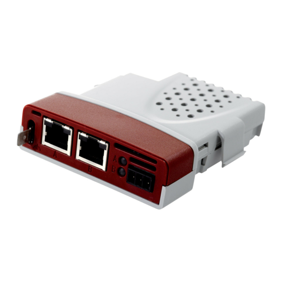
User Guide SM-EtherCAT Unidrive SP Affinity Digitax ST Commander SK Mentor MP Part Number: 0471-0128-02 Issue: 2 www.controltechniques.com... - Page 2 General Information The manufacturer accepts no liability for any consequences resulting from inappropriate, negligent or incorrect installation or adjustment of the optional parameters of the equipment or from mismatching the variable speed drive with the motor. The contents of this guide are believed to be correct at the time of printing. In the interests of commitment to a policy of continuous development and improvement, the manufacturer reserves the right to change the specification of the product or its performance, or the content of the guide without notice.
-
Page 3: Table Of Contents
Safety Information ...5 Warnings, cautions and notes ...5 Electrical safety - general warning ...5 System design and safety of personnel ...5 Environmental limits ...6 Compliance with regulations ...6 Motor ...6 Adjusting parameters ...6 General safety considerations for remote operation ...7 Introduction ...8 Features ...8 Introduction to SM-EtherCAT ...8... - Page 4 Diagnostics ...56 Module identification parameters ...56 Network configuration objects ...57 Diagnostic parameters ...58 Drive trip display codes ...59 SM-EtherCAT module temperature ...59 SM-EtherCAT serial number ...59 SM-EtherCAT error codes ...60 Critical task % free ...61 Worst case critical task % free ...61 9.10 FLASH file system % free ...61 9.11...
-
Page 5: Safety Information
Safety Information Warnings, cautions and notes A Warning contains information, which is essential for avoiding a safety hazard. WARNING A Caution contains information, which is necessary for avoiding a risk of damage to the product or other equipment. CAUTION A Note contains information, which helps to ensure correct operation of the product. NOTE Electrical safety - general warning The voltages used in the drive can cause severe electrical shock and/or burns, and... -
Page 6: Environmental Limits
Careful consideration must be given to the functions of the drive which might result in a hazard, either through their intended behavior or through incorrect operation due to a fault. In any application where a malfunction of the drive or its control system could lead to or allow damage, loss or injury, a risk analysis must be carried out, and where necessary, further measures taken to reduce the risk - for example, an over-speed protection device in case of failure of the speed control, or a fail-safe mechanical brake... -
Page 7: General Safety Considerations For Remote Operation
General safety considerations for remote operation SM-EtherCAT enables the possibility of remotely controlling a machine from a distance. It is vital that when connecting to a machine remotely, adequate safety procedures are implemented to prevent damage to the machine or injury to personnel. Any connection to a live system has the possibility of altering the state of the machine, adequate procedures must be implemented to cover this situation. -
Page 8: Introduction
Introduction Features • Standard RJ45 connectivity with support for shielded twisted pair. • Dual 100Mbps EtherCAT interfaces for use in line topologies i.e. daisy chaining. • Supports the Unidrive SP drives range, Mentor MP, Affinity, Digitax ST and Commander SK. •... -
Page 9: Conventions Used In This Guide
2.4.1 Date code format The date code is split into two sections: a letter followed by a number. The letter indicates the year and the number indicates the week number (within the year) in which the Solutions Module was built. The letters are alphabetical in order, starting with A in 1991 (B in 1992, C in 1993 etc.). -
Page 10: Mechanical Installation
Mechanical Installation Before installing or removing a Solutions Module in any drive, ensure the AC supply has been disconnected for at least 10 minutes and refer to Chapter 1 Safety Information on page 5. If using a DC bus supply ensure this is fully discharged before working on any drive or Solutions Module. -
Page 11: Electrical Installation
Electrical Installation SM-EtherCAT module information 4.1.1 Bus media The SM-EtherCAT option module incorporates two x 100 BASE-TX RJ45 interfaces. 4.1.2 Cabling considerations To ensure long-term reliability it is recommended that any cables used to connect a system together be tested using a suitable Ethernet cable tester, this is of particular importance when cables are constructed on site. -
Page 12: Network Topology
Network topology Control Techniques recommend implementing daisy chaining on EtherCAT networks (see Figure 4-1). Other Ethernet network topologies can be used but care must be taken to ensure that the system still operates within the constraints specified by the designer. Figure 4-1 SM-EtherCAT daisy chain network topology Master / PLC Minimum node-to-node cable length... -
Page 13: Getting Started
Getting Started Quick start guide This section is intended to provide a generic guide for setting up SM-EtherCAT with a master/controller PLC. It will cover the basic steps required to get cyclic data communicating using the CANopen over EtherCAT (CoE) protocol on the SM-EtherCAT module. - Page 14 5.1.3 Configuring the SM-EtherCAT module for cyclic communications Unlike other Control Techniques fieldbus communication protocols, CoE does not require that any module parameters be changed in order to achieve communications. The baud rate of the network is fixed and the module is automatically allocated an address.
- Page 15 For this example the following objects will need to be set in order to achieve the mappings of the parameters/objects in the PDOs. Table 5.3 Cyclic data mapping configuration RxPDO1: Object: 0x1600 Sub-index: 0x00 Size: Value: Sub-index: 0x01 Size: Value: 0x60400010 Value: Sub-index: 0x02 Size:...
- Page 16 Assigning RxPDO to the Sync Manager To assign RxPDO1 to sync manager 2 PDO assignment set the values below to the following objects: • Index: 0x1C12 • Sub index: 0x00 • Size: 1 • Value: 1 Setting object 0x1C12, sub-index 0 to a value of 1 (as above) indicates that one RxPDO will be assigned to the sync manager 2 assignment.
-
Page 17: Quick Start Flowchart
Quick start flowchart Figure 5-3 details the steps required to achieve cyclic communications on the EtherCAT network. This flowchart should be used as the starting point for all configurations. Figure 5-3 Quick start flowchart Ensure the Control Techniques .xml file is in the appropriate Configure the Sync managers using the required PDOs Check the front of the SM-EtherCAT module to ensure that the LED relating to the connection being used is flashing , this... -
Page 18: Saving Parameters To The Drive
Saving parameters to the drive On the Unidrive SP, Affinity, Digitax ST and Commander SK to avoid loss of the configured settings when the drive is powered down it is necessary to write 1000 to Pr MM.00 followed by pressing the reset button to perform a drive save. On Mentor MP Pr MM.00 needs to be set to a value of ‘SAVE’... -
Page 19: Protocols
Protocols CANopen over EtherCAT (CoE) The CoE protocol over EtherCAT uses a modified form of the CANopen object dictionary. This is specified in Table 6.1: Table 6.1 CoE object dictionary Index 0x0000 to 0x0FFF 0x1000 to 0x1FFF 0x2000 to 0x5FFF 0x6000 to 0x9FFF 0xA000 to 0xFFFF The object description format describes object related information such as size, range... - Page 20 Definitions: • <index> : A signed 16-bit number. This is the index of the object dictionary entry specified in four hexadecimal characters. • <access> : A value describing how the object may be accessed (RW = read/ write, RO = read-only and WO = write-only). •...
- Page 21 6.1.2 RxPDO mappings Objects with indices from 0x1600 to 0x17FF specify receive PDO mappings. The mappings from DSP-402 are included as standard (the PDO mappings will have the following default values): Table 6.6 RxPDO mappings PDO number The RxPDO mappings objects are defined below. Each mapping object has the maximum number of sub-indices (each representing an object mapped to a PDO) defined in the XML configuration file (specified as “CF”...
- Page 22 Table 6.8 RxPDO mapping 2 0x1601 Receive PDO mapping 2 Sub-index 0: Number of mapped objects Access: RW Default: Description: The number of mapped objects in this PDO. Sub-index 1: 1st mapped object Access: RW Default: 0x60400010 - the DSP-402 control word (0x6040) Description: A mapping to an object with the following format: Bits 0 to 7: Length of the mapped object in bits, e.g.
- Page 23 Table 6.10 RxPDO mapping 22 0x1615 Receive PDO mapping 22 Sub-index 0: Number of mapped objects Access: RW Default: Description: The number of mapped objects in thie PDO Sub-indices 1 to 255: 1st to 255th mapped objects in this PDO. Access: RW Default: Description:...
- Page 24 Table 6.13 TxPDO mapping 2 0x1A01 Transmit PDO mapping 2 Sub-index 0: Number of mapped objects Access: RW Default: Description: The number of mapped objects in this PDO. Sub-index 1: 1st mapped object Access: RW Default: 0x60410010 - the DSP-402 status word (0x6041) Description: A mapping to an object with the following format: Bits 0 to 7: Length of the mapped object in bits, e.g.
- Page 25 Table 6.15 TxPDO mapping 6 0x1A05 Transmit PDO mapping 6 Sub-index 0: Number of mapped objects Access: RW Default: Description: The number of mapped objects in this PDO. Sub-index 1: 1st mapped object Access: RW Default: 0x60410010 - the DSP-402 status word (0x6041) Description: A mapping to an object with the following format: Bits 0 to 7: Length of the mapped object in bits, e.g.
- Page 26 6.1.4 Sync manager configuration The sync managers are the EtherCAT means for setting access attributes for different areas of memory and triggering or notifying the application when the memory is accessed. The following objects specify how the sync managers (and thus corresponding memory areas) are utilised by the CoE protocol.
- Page 27 Table 6.20 Sync manager 2 PDO assignment object 0x1C12 Sync manager 2 PDO assignment Sub-index 0 Access: RW Default: Description: The number of RxPDOs assigned to this sync manager (used for process data output). Sub-indices 1 to (sub-index 0) Access: RW Default: 0x1605 Description:...
-
Page 28: Drive Profile (Dsp-402) Support
LEGEND: ms = manufacturer-specific; r = reserved; oms = operation mode specific; h = halt; fr = fault reset; hos = homing operation start; eo = enable operation; qs = quick stop; ev = enable voltage; so = switch on Table 7.3 Command coding... -
Page 29: 0X6041 Statusword
LEGEND: ms = manufacturer-specific; ha = homing attained; oms = operation mode specific; ila = internal limit active; tr = target reached; rm = remote; w = warning; sod = switch on disabled; qs = quick stop; ve = voltage enabled; f = fault; oe = operation enabled; so = switched on; rtso = ready to switch on Table 7.6 State coding... - Page 30 ‘SWITCH ON DISABLED’ state to the ‘READY TO SWITCH ON’ state. If the master leaves the operational state while the state machine is in the ‘SWITCH ON’, ‘OPERATION ENABLE’ , ‘QUICK STOP ACTIVE’ or ‘READY TO SWITCH ON’...
- Page 31 Figure 7-1 CoE state machine diagram Power disabled Shutdown Switch On Enable operation Shutdown Disable voltage SM-EtherCAT User Guide Issue Number: 2 Any drive trip START Drive not Pr 10.01 = 1 tripped NOT READY TO SWITCH ON Pr 10.02 = 0...
- Page 32 The high-power shall be switched off immediately if possible, and the motor The quick stop function shall be started device or local signal The power section shall be switch off option code) Fault signal Automatic transition The drive function shall be disabled; the...
- Page 33 Definition Disable drive function Slow down on slow down ramp and transit into Switch on disabled Slow down on quick stop ramp and transit into Switch on disabled Slow down on slow down ramp and stay in Quick stop active Slow down on quick stop ramp and stay in Quick stop active www.controltechniques.com...
- Page 34 7.3.3 0x605B Shutdown_option_code This object is used to control what action is performed if there is a transition from the Operation Enabled state to the Ready To Switch On state. Table 7.11 Shutdown_option_code 0x605B Shutdown_option_code Access: RW Default: Description: Used to control what action is performed if there is a transition from the Operation Enabled state to the Ready To Switch On state.
- Page 35 7.3.6 0x6060 Modes_of_operation This object is used to request a change in the mode of operation. Table 7.17 Modes_of_operation 0x6060 Modes_of_operation Access: RW Default: Description: This object is used to request a change in the mode of operation. Table 7.18 Modes_of_operation values Value 7.3.7 0x6061 Modes_of_operation_display...
- Page 36 7.3.9 Profile units The implementation provides a means to convert profile units into position controller and drive units. All scaling values are standard profile objects. The following objects are supported: Table 7.22 Supported profile units Index 0x608F 0x6091 0x6092 For positions, the scaling control includes a feed constant, a gear ratio and an encoder revolution.
- Page 37 Table 7.24 Gear_ratio 0x6091 Gear_ratio Sub-index 0 Access: RO Default: Description: Sub-index 1 Access: RW Default: Description: Motor revolutions Sub-index 2 Access: RW Default: Description: Shaft revolutions 7.3.12 0x6092 Feed_constant This is used to configure a feed constant. This is the measurement distance per one revolution of the output shaft of the gearbox.
- Page 38 Table 7.26 lists the objects that are supported: Table 7.26 Basic position control supported objects Index 0x6062 0x6064 0x6065 0x6067 0x60F4 0x60FB 7.3.14 0x6062 Position_demand_value This read only object is used to provide the currently demanded position value. The value is given in user defined position units. Table 7.27 Position_demand_value 0x6062 Position_demand_value...
-
Page 39: Interpolated Position Mode
7.3.17 0x60FB Position_control_parameter_set object Table 7.30 Position_control_parameter_set object 0x60FB Position_control_parameter_set Sub-index 0 Access: RO Default: Description: The number of control loop parameters. Sub-index 1 Access: RW Default: 2500 Description: The position controller proportional gain. Sub-index 2 Access: RW Default: 1000 (i.e. a gain of 1) Description: The position controller speed feed forward gain. - Page 40 7.4.2 0x60C1 Interpolation_data_record This object is used to specify the target position. Linear interpolation is used to generate position demand values every 250µs. The position is specified in user-defined position units. The value is written into sub-index 1. Table 7.33 0x60C1 Interpolation_data_record 0x60C1 Interpolation_data_record Sub-index 0...
-
Page 41: Vl Velocity Mode
The time period is checked to ensure that it is an integer multiple of the control loop cycle time. Only linear interpolation is currently supported. This type inserts a delay of one interpolation time period. The input buffer has a maximum size of 1 data record, and a data record contains one position in profile-defined units. - Page 42 7.5.2 0x6043 vl_velocity_demand This read only object provides the instantaneous velocity demand generated by the drive ramp function. The value is given in rpm if the vl_dimension_factor and the vl_setpoint_factor have the value 1, otherwise the value is in user units. Positive values indicate forward direction and negative values indicate reverse direction.
- Page 43 7.5.5 0x6047 vl_velocity_min_max This object is used to configure the minimum and maximum velocity. The value is given in rpm if the vl_dimension_factor has the value of 1, otherwise the value is in user units. Table 7.41 0x6047 vl_velocity_min_max 0x6047 vl_velocity_min_max Sub-index 0 Access: RO...
- Page 44 7.5.7 0x6049 vl_velocity_deceleration This object is used to configure the delta speed and delta time of the slope of the deceleration ramp. Example: To decelerate by 800 rpm in 10s, possible values for delta speed and delta time are 8000 and 100 respectively. vl_velocity_deceleration = delta speed / delta time Table 7.43 0x6049 vl_velocity_deceleration 0x6049...
- Page 45 7.5.9 0x604B vl_setpoint_factor This object is used to configure the numerator and denominator of the vl_setpoint_factor. The vl_setpoint_factor modifies the resolution or directing range of the specified setpoint. It does not influence the velocity limit function and the ramp function. A value of 0 must not be used. Table 7.45 0x604B vl_setpoint_factor 0x604B vl_setpoint_factor...
-
Page 46: Profile Torque Mode
The object vl_velocity_min_max is handled every profile cycle. The vl_target_velocity is limited according to the values set in the object vl_velocity_min_max, which is read every profile cycle. The object vl_velocity_min_max_amount is mapped to vl_velocity_min_max. The value of the vl_velocity_demand object is calculated in the background. The option reads the value of parameter Pr 2.01 (post ramp reference), scaled from RPM to user units using vl_dimension_factor and vl_setpoint_factor, and writes the value to the vl_velocity_demand object. -
Page 47: Homing Mode
7.6.2 0x6075 Motor_rated_current This object indicates the configured motor rated current. It is taken from the motor’s name-plate. Depending on the motor and drive technology this current is DC, peak or rms (root-mean-square) current. All relative current data refers to this value. The value of this object is given in mA. - Page 48 48, the initial direction of movement shall be rightward if the positive limit switch is inactive (here: low). The position of home shall be at the first index pulse to the left of the position where the positive limit switch becomes inactive.
- Page 49 49, the initial direction of movement shall be dependent on the state of the home switch. The home position shall be at the index pulse either to the left or the right of the point where the home switch changes state. If the initial position is sited so that the direction of movement shall reverse during homing, the point at which the reversal takes place is anywhere after a change of state of the home switch.
- Page 50 11 to 14 the initial direction of movement shall be to the left except if the home switch is active at the start of the motion. In this case the initial direction of motion shall be dependent on the edge being sought. The home position shall be at the index...
- Page 51 These methods are similar to methods 1 to 14 except that the home position is not dependent on the index pulse but only dependent on the relevant home or limit switch transitions. For example methods 19 and 20 are similar to methods 3 and 4 as shown in Figure 7-9 Homing on positive home switch on page 51.
- Page 52 Access: RW Default: 5 Description: The source of the homing switch. This will specify a digital input as follows: 1 to 6 - The number of a Drive digital input 7 to 8 - SM-EtherCAT option module digital input 0 or 1...
- Page 53 0x2804 Freeze object This object is used to configure the freeze function that can be used within the Homing mode profile. Table 7.55 Freeze object on page 53 specifies the object description. Table 7.55 Freeze object Freeze object 0x2804 Sub-index 0 Access: RO Default: 2 Description: The number of the last sub-index in this object.
- Page 54 Access: C Default: 2 Description: The number of supported sub-indices. Sub-index 1 Access: RW Default: 0 Description: Speed during search for a switch. Sub-index 2 Access: RW Default: 0 Description: Speed during search for a zero. 0x609A Homing acceleration This object indicates the configured acceleration and deceleration to be used during the homing operation.
-
Page 55: Advanced Features
Advanced features Distributed clocks SM-EtherCAT supports Distributed clocks. This is the scheme used by EtherCAT to accurately time synchronize slave devices. Position, speed and current control loops can all be synchronized. When the option module is connected to a drive which can take a time synchronization signal (e.g. -
Page 56: Diagnostics
Diagnostics Module identification parameters The basic menu parameters can be accessed through the slot menu in the drive, Pr MM.PP, where MM is the menu for SM-EtherCAT in the host drive. The basic menu parameters may also be accessed using menu 60, i.e. Pr 60.PP. 9.1.1 SM-EtherCAT module ID code Table 9.1 SM-EtherCAT module ID code... -
Page 57: Network Configuration Objects
Commander SK / Commander SL The software version of the Solutions Module can be identified by looking at Pr 15.02 and Pr 15.51. The software version takes the form of xx.yy.zz, where Pr 15.02 displays xx.yy and Pr 15.51 displays zz (e.g. for software version 01.01.00 Pr 15.02 will display 1.01 and Pr 15.51 will display 0). -
Page 58: Diagnostic Parameters
Diagnostic parameters Table 9.5 SM-EtherCAT operating status SM-EtherCAT operating status Pr MM.06 9.3.1 Running states Table 9.6 Diagnostic information - running states Pr MM.06 Meaning Link established > 0 Handled messages per second Table 9.7 Diagnostic information - application Pr MM.06 Meaning Application started Initialising file system... -
Page 59: Drive Trip Display Codes
Drive trip display codes If the SM-EtherCAT detects an error during operation, it will force a trip on the drive. However, the trip code displayed on the drive will only indicate which slot initiated the trip. The exact reason for the trip will be indicated in the SM-EtherCAT error code parameter, Pr MM.50. -
Page 60: Sm-Ethercat Error Codes
SM-EtherCAT error codes Table 9.12 SM-EtherCAT error codes SM-EtherCAT error codes Pr MM.50 If an error is detected during operation the module will force a trip on the drive and update the error code parameter (Pr MM.50). Table 9.13 shows the SM-EtherCAT error codes. -
Page 61: Critical Task % Free
Critical task % free Table 9.14 SM-EtherCAT critical task % free SM-EtherCAT critical task % free Default Pr MM.46 Range Access Worst case critical task % free Table 9.15 Worst case critical task % free SM-EtherCAT worst case critical task % free Default Pr MM.47 Range... -
Page 62: Quick Reference
Quick Reference Table 10.1 and Table 10.2 list of all the SM-EtherCAT set-up objects and parameters that are required to configure the module. Table 10.1 SM-EtherCAT objects reference Object Name 0x10000 Device type 0x1018 Identity object Receive PDO 0x1600 mapping 1 Receive PDO 0x1601 mapping 2... - Page 63 Used to control what action is performed if there is a transition from the Operation Enabled state to the Ready To Switch On state. This object is used to control what action is performed if there is a transition from the Operation Enabled state to the Switched On state.
- Page 64 Table 10.1 SM-EtherCAT objects reference Object Name Interpolation 0x60C0 sub-mode_select Interpolation 0x60C1 data_record Interpolation 0x60C2 time_period Table 10.2 SM-EtherCAT parameter reference Object Description SM-EtherCAT Pr MM.01 module ID code SM-EtherCAT Pr MM.02 firmware - major version SM-EtherCAT Pr MM.06 operating status SM-EtherCAT re- Pr MM.32 initialise...
-
Page 65: Glossary Of Terms
Glossary Of Terms Address: This is the unique network identification given to a networked device to allow communication on a network. When a device sends or receives data the address is used to determine the source and the destination of the message. Bit: A binary digit, this may have the value of 1 or 0. -
Page 66: Www.controltechniques.com Issue Number
Scan rate: See Poll rate. Screening: A connection to provide additional immunity to noise used on a network cable. Shielding: A connection to provide additional immunity to noise used on a network cable. Status word: A value that denotes the status of the drive. Each bit within the word will have a specific meaning. - Page 67 Address ...65 Adjusting parameters ...6 Bit ...65 Byte ...65 Control word ...65 Cyclic data ...65 Data rate ...65 Device ...65 Diagnostics ...56 Domain ...65 Earthing ...65 Electrical installation ...11 Electrical safety ...5 Functional blocks ...19 Getting started ...13 Glossary of terms ...65 Homing mode ...47 Index ...67 Introduction ...8...
- Page 68 PC ...65 PLC ...65 Poll rate ...65 Quick Reference ...62 Safety considerations ...7 Safety information ...5 SECURE DISABLE ...5 Status word ...66 Word ...66 SM-EtherCAT User Guide www.controltechniques.com Issue Number: 2...
- Page 70 0471-0128-02...
Need help?
Do you have a question about the SM-ETHERCAT 0471-0128-02 and is the answer not in the manual?
Questions and answers