Table of Contents
Advertisement
Quick Links
Date of last update: Apr-16
DWM C
O
1
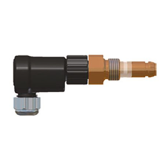
Introduction
Electronic switch
Mechanical sensor
OPS2
The mechanical sensor fitting for the OPS2 is the same as for the OPS1. The electronic switches are
interchangeable but require changes to the wiring circuit.
2
Function
The OPS2 is activated by the running signal of the compressor contactor. If the oil pressure differential drops below
the preset value for longer than the time delay (120 seconds) the output contact of the OPS2 opens and stops the
compressor providing protection against internal damage. Repeated shorter periods of insufficient oil pressure are
also recognized and will shut off the compressor after an appropriate time delay.
Start of monitoring
Compressor start
Figure 1: Functional graph using pressure differential x time axes
3
Operation
There is a 3-second delay after power is supplied to the OPS2 before the relay pulls in and the compressor is
ready to start. Once running the compressor contactor provides the signal to the OPS2 (D1). The differential
pressure monitoring will only start when the running recognition D1 signal is present. After a delay of 5 seconds the
OPS2 starts monitoring.
D7.8.3/0416/E
™ S
OPELAND
EMI
P
D
IL
RESSURE
IFFERENTIAL
The OPS2 monitors the oil pressure differential protecting the
compressor against damage if the oil differential becomes too low.
Internal channels drilled through the housing link the switch to the
inlet and outlet ports of the oil pump.
The brass mechanical sensor component is fitted as standard on
all DWM Semi-Hermetic compressors which have a high pressure
oil pump. It is directly screwed into the pump housing. The black
electronic switch is screwed onto the brass mechanical sensor. If
the electronic switch has to be removed from the brass sensor the
refrigeration circuit will not be open to the atmosphere.
∆p low for only a short time
Compressor will not stop
C
-H
ERMETIC
OMPRESSORS
S
WITCH
Not to scale
0.95∆p
Compressor stop
Ref: D7.8.3/0416/E
Application Engineering Europe
OPS2
1/5
Advertisement
Table of Contents

Related Manuals for Emerson DWM COPELAND OPS2


Summary of Contents for Emerson DWM COPELAND OPS2
- Page 1 Date of last update: Apr-16 Ref: D7.8.3/0416/E Application Engineering Europe DWM C ™ S OPELAND ERMETIC OMPRESSORS OPS2 RESSURE IFFERENTIAL WITCH Introduction The OPS2 monitors the oil pressure differential protecting the Electronic switch Mechanical sensor compressor against damage if the oil differential becomes too low. Internal channels drilled through the housing link the switch to the inlet and outlet ports of the oil pump.
- Page 2 In case of failure or incorrect assembly registered for more than 5 seconds, the relay will trip and lock out. Methods to reset the switch after shutdown: Push the internal reset button (1 sec) Disconnect the switch from the power supply – mains interruption (5 sec) ...
- Page 3 Where a 5- or 7-wire cable is stated a 4- or 6-wire cable is required. In some countries only a 5- or 7- NOTE: wire cable is available. Wiring: Brown ( ) = Power supply input Violet ( ) = Running signal from compressor Grey ( ) = Input changeover contact from daisy chain Orange (...
- Page 4 Function testing The OPS2 has to be set up as normal with fuses removed from power supply to compressor. The control circuit should still be live. Correct assembly control test Alarm contact switches to compressor contactor Control power supply ON (GR-PK to GR-OG) Signal for incorrect assembly - LED code (fast light 10Hz) - Remove electronic switch...
- Page 5 Wiring diagrams of OPS1 and OPS2 The electrical part of the OPS1 can be replaced by the OPS2 module. Please see connection diagram proposals below. 5-wire connecting cable between electrical control panel and compressor terminal box With a 5-wire connecting cable to the OPS module, one can duplicate the functions of the OPS1 with the OPS2. 7-wire connecting cable between electrical control panel and compressor terminal box With a 7-wire connecting cable the full function range of the OPS2 can be used.
Need help?
Do you have a question about the DWM COPELAND OPS2 and is the answer not in the manual?
Questions and answers