Emerson AVOCENT Installer/User Manual
Matrix high performance kvm switching system
Hide thumbs
Also See for AVOCENT:
- User manual (60 pages) ,
- User manual (14 pages) ,
- Quick installation manual (2 pages)

Related Manuals for Emerson AVOCENT


Summary of Contents for Emerson AVOCENT
- Page 1 ® M KVM S VOCENT ATRIX ERFORMANCE WITCHING YSTEM NSTALLER UIDE...
- Page 2 ...
- Page 3 All other marks are the property of their respective owners. This document may contain confidential and/or proprietary information of Avocent Corporation, and its receipt or possession does not convey any right to reproduce, disclose its contents, or to manufacture or sell anything that it may describe.
- Page 4 ...
-
Page 5: Table Of Contents
T A B L E O F C O N T E N T S Product Overview Features and Benefits Security Flash upgrade Video support Audio support USB support On-Board Web Interface (OBWI) On-Screen Display (OSD) Matrix switch Receiver Transmitter Installation and Configuration Configuration Options... - Page 6 Matrix High Performance KVM Switching System Installer/User Guide Users – Targets tab Users – Favorites tab Users – OSD tab Users – OSD F1-F12 tab Users – Status tab Devices Tab Restore defaults Update firmware Reboot device Remove device...
- Page 7 Table of Contents iii Info Tab Diagnostics Tab Appendices Appendix A: Technical Specifications Appendix B: Cable Pinout Information Appendix C: Technical Support ...
- Page 8 Matrix High Performance KVM Switching System Installer/User Guide...
-
Page 9: Product Overview
Product Overview The Avocent® M atrix High Performance KVM switching system is the next generation of Avocent keyboard, video and mouse (KVM) products. This new class of digital Matrix systems and extension products provides the high-performance, reliable desktop extension experience expected from an Avocent product. Combining the best of the previous generation, such as the instantaneous switching time of the Avocent AMX™ switching system and the digital quality and advanced management features of the Avocent HMX extender system, the digital Matrix switching solution offers a way to migrate to a digital solution w hile leveraging e xisting infrastructure. In a typical scenario, numerous transmitter and receiver devices can connect in a Matrix fashion to communicate through the proprietary central switch or a network of switches. The switch h andles the distribution of the data streams between transmitters and receivers. A single s hielded twisted pair (STP) CAT 5e/6 cable, connects each transmitter and receiver to the switch. Users are linked to computers in real-time across a Matrix that connects video, USB peripherals and audio from a target computer to a receiver where the user can operate as if the computer is directly connected to a monitor, USB peripherals and speakers. The Matrix Switching System is the basis for an additional set of products intended to address t he digital signage and Pro A/V, as IT and A/V equipment converge. This unified approach p rovides an enhanced digital Matrix switching solution f or broadcast, post production and data centers (government, military and industrial). Features and Benefits • Transmitters are powered from the switch over STP CAT 5e/6 • ... -
Page 10: Video Support
2 Avocent® Matrix High Performance KVM Switching System Installer/User Guide Video support The advanced Dambrackas Video Compression™ algorithm used by the system enables a pixel-accurate video experience with lag-free, real-time interaction with computing equipment. The resulting performance and speed provide new levels of content creation, production and delivery. Video is distributed in multiple formats supporting various connectors including D VI-D and VGA. Audio support The Matrix receiver provides CD quality (Redbook) 44.1 kHz, 16-bit per channel stereo audio support. USB support The Matrix Switching System provides six USB version 2.0 connectors with an industry-leading combined throughput. On-Board Web Interface (OBWI) Administrators can manage the system through the OBWI (accessed with HTTPS). The OBWI runs on any supported browser that has network access to the switch. An administrator can use the OBWI to create user accounts and configure transmitters and receivers. On-Screen Display (OSD) The Matrix receiver includes an on-screen display that allows users to establish connections to the targets from the local keyboard and mouse. Matrix switch The Matrix switch is a rack mountable chassis with R J-45 ports to which the transmitters, receivers and switches connect. I t is available in 20-port and 32-port models. T he interconnection at the switch is a proprietary, non- routable protocol. • ... -
Page 11: Receiver
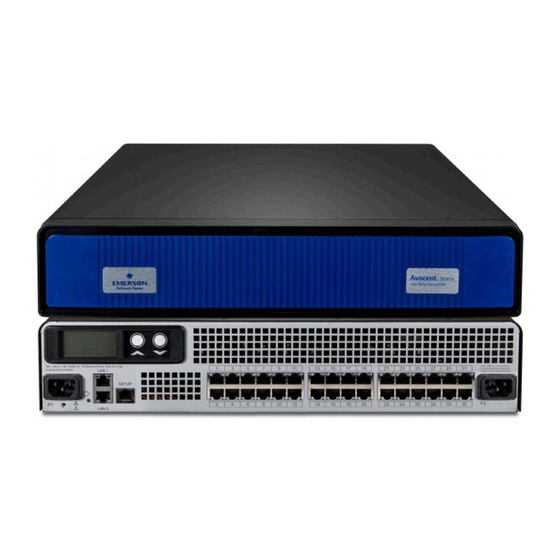
Chapter 1: Product Overview 3 Figure 1.1: Avocent™ Matrix Switch Table 1.1: Avocent™ Matrix Switch Descriptions Number Description Power supplies (dual on 32-port switch) RGB LCD and scroll buttons for device information Dual NIC ports Setup port RJ-45 ports for KVM signaling Receiver The Matrix receiver enables the desktop user’s m onitor, speakers and USB peripherals to connect to a target computer through the Matrix switch. ... -
Page 12: Transmitter
4 Avocent® Matrix High Performance KVM Switching System Installer/User Guide Figure 1.2: Avocent™ Matrix Receiver Table 1.2: Avocent™ Matrix Receiver Descriptions Number Description RGB LCD for color-coded status and device information Audio connection Microphone connection USB 2.0 connections External power button for turning on/off and resetting the receiver T-Channel locking for secure rack mounting USB 2.0 connections... - Page 13 Chapter 1: Product Overview 5 Figure 1.3: Avocent™ Matrix Transmitter Table 1.3: Avocent™ Matrix Transmitter Descriptions Number Description RGB LCD for color-coded status and device information T-Channel locking for secure rack mounting Audio connection Microphone connection DVI-D or VGA video connection USB-B connector RJ-45 port for connection to the Matrix switch...
- Page 14 6 Avocent® Matrix High Performance KVM Switching System Installer/User Guide...
-
Page 15: Installation And Configuration
Installation and Configuration At this point you should have already mounted the switch and completed the installation instructions outlined in the Avocent® Matrix Switching System Quick Installation Guide. For important safety information on your Matrix switch, please visit http://www.emersonnetworkpower.com/ComplianceRegulatoryInfo. Configuration Options Single switch Matrix system In the figure below, multiple transmitters and receivers are attached to a single Matrix switch. Figure 2.1: Example of Single Switch System Table 2.1: Single Switch System Components Number Description Target device Matrix transmitter Matrix switch Matrix receiver Audio connection (speakers) Video connection Microphone connection Mouse connection Keyboard connection... -
Page 16: Multi-Switch Cascaded Matrix System
8 Avocent® Matrix High Performance KVM Switching System Installer/User Guide Multi-switch cascaded Matrix system Up to four Matrix switches may be interconnected to create a larger switching system capable of supporting more receivers and transmitters. This is referred to as a cascaded system. When cascading Matrix switches, you can seamlessly connect to any target device from a single list in the On-screen Display (OSD) interface, as if all the target devices were connected to one switch. T o use seamless cascading, you will need to configure the cascaded switches as a master and slave(s). There can be only one master in a cascaded system. The switch that is set to master mode is used to administer the other switches, transmitters and receivers in the system through the OBWI. In a system with only one switch, that switch should always be set to master mode. When a switch is set to slave mode, the web user interface on the switch will become very limited. A slave cannot administer other devices. Figure 2.2: Example of a Multi-switch Cascaded System Table 2.2: Cascaded Switch System Components Number Description Matrix transmitter Matrix switch Matrix receiver Ethernet IP connection Direct connection To install a cascaded Matrix Switching System: 1. Position the Matrix switches to be attached and select a switch to be the master switch. 2. Attach one end of an STP c able into a numbered RJ-45 port on the master switch. Attach the other end of ... -
Page 17: Switch Configuration
Chapter 2: Installation and Configuration 9 Switch Configuration After the Avocent Matrix Switching System has been installed, you can begin configuration. By default, DHCP is enabled on the switch. Once the switch receives an IP address, it is displayed on the LCD display on the back of the unit. You can begin configuration by using the setup port or using the On-board Web Interface (OBWI). For more information on the OBWI setup, see On-Board Web Interface on page 13. Setup Port The setup port on the back of the Matrix switch allows the administrator access to a menu for setup and configuration of the switch. From the serial menu you can configure network settings, setup or change passwords, upgrade the firmware or reset to factory defaults. NOTE: The default username and password is Admin with no password. When you login for the first time, you will be prompted to change the password. -
Page 18: Appliance Mode
10 Avocent® Matrix High Performance KVM Switching System Installer/User Guide Option Description The switch attempts to obtain an IP address using DHCP. If DHCP times out, then it uses zeroconf to obtain an IP address. Zeroconf picks an IP address out DHCP plus zeroconf of the block 169.254.0.0/16. -
Page 19: Set Session Timeout
Chapter 2: Installation and Configuration 11 Set session timeout The set session timeout option configures the setup port inactivity timeout. When the timeout for the setup port expires, the user is logged out. - Page 20 12 Avocent® Matrix High Performance KVM Switching System Installer/User Guide...
-
Page 21: On-Board Web Interface
NOTE: The OBWI and the Setup port use the same administrator account. The following browsers are compatible with the OBWI: ® • Microsoft Internet Explorer 9 or 10 ® • Mozilla Firefox 17 Extended Service Release To log in to the Matrix switch OBWI: 1. Launch a web browser. 2. In the address field, enter the IP address of the Avocent™ Matrix switch. Use https://<IP Address> as the format. 3. Enter your username and password, then click Login. NOTE: The default username and password is Admin with no password. -
Page 22: Common Features
14 Avocent® Matrix High Performance KVM Switching System Installer/User Guide Figure 3.1: On-Board Web Interface Table 3.1: On-Board Web Interface (OBWI) Number Description Tab bar - Use the tab bar to display and manage users, sessions, devices, peripherals, settings and events. Side bar- The sidebar is used to initiate actions related to the current tab. The content of the sidebar changes depending on which tab is selected. -
Page 23: Forgotten Password
Chapter 3: On-Board Web Interface 15 Forgotten password If you forget the administrator password, contact technical support. OBWI Help You can access the online help for the Matrix switch by clicking the Help button in the top right of the screen. Dashboard Tab When you login to the OBWI, the tab that is shown by default is the Dashboard tab. The Dashboard tab displays current session information, user information and events. Figure 3.2: Dashboard Tab User sessions pane The user sessions pane lists the current KVM sessions and details the user that is logged in, the transmitter and receiver that are being used by the KVM session, whether the session is shared or private and how long the session has been active. Events pane The events pane displays a list of recent events including the date and time of the event, the type of event and a brief description. The events can be either informational events or errors that may require further attention. Sessions Tab The Sessions tab allows you to view and connect or disconnect KVM sessions. ... -
Page 24: Users Tab
16 Avocent® Matrix High Performance KVM Switching System Installer/User Guide Figure 3.3: Sessions tab in OBWI When a specific session is selected, the details are displayed in the bottom Session Details pane. The session details are read only. To connect a KVM session: 1. On the sidebar under Connect Session, click Connect. 2. From the drop-down list, select either Private or Shared session (other authorized users will be able to join a shared session). 3. Select the username, receiver and transmitter. When you select a username, the list of receivers is populated according to the rights of that user and the allowed shared/private mode(s) of each receiver. When you select a receiver, the list of transmitters is populated according to the rights of the user and the allowed shared/private mode(s) of each transmitter. 4. Click Connect. To disconnect a session: 1. Select a session from the list of active sessions. 2. On the sidebar under Disconnect Session, click Disconnect. Users Tab The Users tab is used for creating, deleting and logging users in or out of receivers. An administrator must create a user account for each user. There is a limit of 8 0 user accounts on a master switch. The administrator account on a slave switch can be used to change a limited amount of settings on the slave switch. NOTE: Slave switches do not have user accounts except for the administrative account. -
Page 25: New User
Chapter 3: On-Board Web Interface 17 Figure 3.4: Users Tab New user When a user has been created, you can configure the permissions, targets, OSD settings and set up a list of favorites for the user. By s electing more than one user, you can change the permissions, targets, settings and favorites for multiple users at the same time. To create a user: 1. On the sidebar under New User, click New. 2. In the Attributes tab, enter the following: a. Username - The name that the user will log in with. It must consist of a combination of up to 20 letters and numbers, must be unique and is case-sensitive. b. Full name - The full name field is for informational purposes only and is not required. c. Allow Blank Password - Select the drop-down list to enable or disable a blank password. d. Change Password - Enable must be selected in order to set the initial user password e. Enter and confirm the password. f. Account Status - Select the drop-down list to choose to Disable or Enable the account. The user will only be able to login if the account is enabled. 3. Click Save. If the Save button is not enabled, there is an error in the Attributes, such as the two password fields not matching. NOTE: The only required field for creating a user is the username on the Attributes tab. Each tab is independent and can be edited after the user has been created. -
Page 26: Login And Logout
18 Avocent® Matrix High Performance KVM Switching System Installer/User Guide 2. On the sidebar under Delete User, click Delete. 3. Click Delete again to confirm. NOTE: You cannot delete all administrator accounts. Login and Logout The Login option allows an administrator to log a user into a specific receiver. The user must have permissions to be able to access the receiver. The Logout user option allows an administrator to log a user out of a receiver. You can select multiple users to be logged out, but you can only log in one user at a time. To log a user into a receiver: 1. From the Users tab, select a user and click Login on the sidebar. 2. Select a receiver f rom the list of available receivers and click Login. To log out a user: 1. From the Users tab, select one or more users and click Logout on the sidebar. 2. Click Logout User to confirm. Users – Attributes tab The user attributes tab is used for editing the user account information including, username, password and the ... -
Page 27: Users - Targets Tab
Chapter 3: On-Board Web Interface 19 NOTE: An administrator can log into the OBWI and perform all functions without restriction. A user can log in only to a Receiver. 4. Select one of the following for the access mode: • Shared Only - The user will only be able to establish shared KVM sessions. • Private Only - The user will only be able to establish private KVM sessions. • Private or Shared - The user will be able to establish either shared or private KVM sessions. 5. Select one of the following for the USB mode: • Disabled - No USB devices will be extended to the target. • ... -
Page 28: Users - Favorites Tab
20 Avocent® Matrix High Performance KVM Switching System Installer/User Guide Users – Favorites tab The Favorites tab allows the administrator to create a quick list of transmitters that are accessed most often by the user. The list can be arranged in any order and can contain up to 32 transmitters. To add a transmitter to favorites: 1. Select one or more users. 2. On the User Details pane, click Favorites. 3. Select one or more transmitters from the list of Available Transmitters and click Add. 4. Select the transmitter from the Favorites List and click Move Up or Move Down to move the transmitter on the lists as desired. The selected order will determine how the transmitters are displayed in the OSD. 5. Click Save. To remove a transmitter from favorites: 1. Select one or more users. 2. On the User Details pane, click Favorites. 3. Select one or more transmitters f rom the Favorites List and click Remove. 4. Click Save. Users – OSD tab The OSD tab allows the administrator to customize the OSD hotkeys and configure the OSD inactivity timeout ... -
Page 29: Users - Status Tab
Chapter 3: On-Board Web Interface 21 To create OSD shortcut keys: 1. Select one or more users. 2. On the User Details pane, click OSD F1-F12. 3. Select the desired function key and then select an action from the drop-down list. 4. The Connect to Target X action requires a specific target to be specified. Select a target from the drop-down list to the right. 5. Click Save. Users – Status tab The Status tab shows the current receiver login and KVM sessions for the selected user(s). Typically, there will be only one session listed per user, but a user can have multiple sessions. The tab displays the username, the receiver, the transmitter and the duration of the session. Devices Tab From the Devices tab, you can manage switches, transmitters and receivers. This includes viewing and changing settings, updating firmware, and resetting to factory defaults. The current list of devices known to the master switch (including itself) is shown in the upper Devices pane. When a new device is physically connected to a switch in the system, it will automatically appear on the list. If a device is physically removed from the system, it will still appear on the list but will show a status of Offline. Settings for that device are retained in the master switch. If the device is connected again in the future, its settings will be pushed from the master switch down to the device. Restore d efaults The restore full defaults option will restore the complete factory default settings to the device(s) selected. The restore partial defaults option applies only to switches. This will restore the factory default settings with the exception of the network settings. Network settings are excluded so that you do not have to reconnect to the switch using a potentially different IP address. Update firmware The update firmware option updates the firmware for the device(s) selected. Firmware can be updated using FTP, HTTP, HTTPS, TFTP, or a local file. Firmware update files are not retained when power is removed or the switch ... -
Page 30: Reboot Device
22 Avocent® Matrix High Performance KVM Switching System Installer/User Guide 4. Click Proceed to proceed with the firmware update. Progress can be seen by watching the status column on the list of Devices pane. The final completion status is logged to the Events tab. Reboot device One or more devices can be rebooted remotely from the Devices tab. To reboot a device: 1. From the Devices tab, select one or more devices and click Reboot. 2. Click Reboot to confirm. The status of the device will change to reboot pending, offline and then back to ready when the device completes rebooting. Remove device Devices that are no longer being used can be removed from the Matrix switch. To remove a device: 1. From the Devices tab, select one or more devices and click Remove. 2. Click Remove to confirm. The device will be removed from the list. Remove offline All offline devices can be removed by using the clicking Remove Offline - Remove. This provides a convenient way for you to clean up your list of devices after one or more devices have been physically removed from the system. Flash display The LCD display can be set to flash to help locate a transmitter, receiver or switch. To flash the LCD display: Select one or more devices, then click Flash in the sidebar. You will be prompted to enter the length of time to ... -
Page 31: Receiver Details
Chapter 3: On-Board Web Interface 23 to slave or slave to master, the switch will automatically reboot to effect the change. There can be only one master in a cascaded system. The switch that is set to master mode is used to administer the other switches, transmitters and receivers in the system through the OBWI. In a system with only one switch, that switch should always be set to master mode. When a switch is set to slave mode, the OBWI on the switch will become very limited. A slave cannot administer other devices. To change the mode: 1. Select a switch from the list of devices. NOTE: You can only change the mode of the switch you are logged in to. 2. On the Mode tab, select the desired cascade participation from the drop-down list. 3. Click Save. Switch – Attributes tab The Attributes tab allows you to change the name, location and description of the switch. The name of each switch must be unique within a cascaded system. Switch – IPv4 and IPv6 tab The IPv4 and IPv6 tabs allow you to choose the configuration method used for the switch, the IP address, the subnet mask, the gateway address and DNS. Switch – NTP tab On the NTP tab you can configure a primary and secondary time server that will be used to synchronize the time ... - Page 32 24 Avocent® Matrix High Performance KVM Switching System Installer/User Guide Table 3.2: Receiver Settings Descriptions Setting Description When enabled, a specified user is automatically logged into the Auto Login receiver whenever it is turned on and physically connected to a switch in the system. When Auto Login is enabled, this identifies the user that will be Auto Login Username logged in to the receiver.
-
Page 33: Transmitter Details
Chapter 3: On-Board Web Interface 25 Transmitter details When in the Devices tab, if you select a transmitter, you will see a list of tabs only applicable to transmitters. Transmitter – Attributes tab The attributes tab allows you to change the name, location and description of the transmitter. Each transmitter within a system must have a unique name. The Location, Description and Notes fields are optional, and are used only for your own information. Transmitter – Settings tab From the settings tab, you can change various settings for the transmitter. The following table describes the transmitter settings. Table 3.3: Transmitter Setting Descriptions Setting Description The icon that will appear on the target list on the OSD to represent this Icon target. Enables the transmitter to send a Wake on LAN signal to the target when a Wake on LAN KVM session is established. -
Page 34: Modes
26 Avocent® Matrix High Performance KVM Switching System Installer/User Guide Modes There are three modes available for users connecting to transmitters and receivers. The modes are Private only, Shared only and Private or Shared. The transmitter setting is the authority if there is conflict in the user or receiver setting. For example, if the transmitter is set to private only and user and/or receiver is set to shared only, the user will not be able to connect to the target. The Private or Shared mode is the default mode for devices. Private mode In Private only mode, n o other receiver in the switching system can switch to that target device. If Private mode is not available, the user will be notified via an on screen message. If the transmitter is configured for p rivate mode only, the share mode option will be grayed out and only private mode will be available. Share mode In Share mode, multiple users can connect to the audio and video of a target computer over the network and arbitrate for control of that computer. Share mode is the default mode, however, if the user has been given access by the administrator they will be able to choose private mode via a radio button. The shared only mode is the default mode for users. Peripherals Tab In order to understand the Peripherals Tab, you need to first understand what an EDID (Extended Display Identification Data) is. EDIDs are built in to video monitors so the computer that a monitor is connected to can query the monitor for its characteristics and capabilities. The computer’s video hardware can then drive the monitor according to the resolution and timing that the monitor can accept. This will affect, for instance, the resolution of the operating system’s desktop display. When a Matrix transmitter is connected to a target computer, the transmitter takes the place of a real monitor, and it must act like a real monitor and present an EDID to the computer when queried. A transmitter with factory default settings will present a generic EDID that represents a fictitious monitor that supports all of the resolutions that can be handled by the Matrix system. You can override this default EDID, by capturing an EDID from an actual monitor connected to a receiver, and ... -
Page 35: System Settings Tab
Chapter 3: On-Board Web Interface 27 EDID information can then be pushed out to any available transmitter. If the transmitter and receiver are running the same resolution, establishing a video connection will be faster because the receiver will not have to change resolution and the monitor will not have to resynchronize with the resolution change. The name of the peripherals and the description can be changed by selecting the monitor and editing the Attributes tab. The manufacturer ID and product code are read only fields. The Monitors list is pre-populated with two read-only entries: the Avocent Default VGA EDID and Avocent Default DVI EDID. These are the factory default monitor attributes (EDIDs) that are presented to an attached target by the VGA and DVI transmitters, respectively. These entries provide a way to get back to the default EDID if you push a different EDID to a transmitter. To pull monitor attributes: 1. On the sidebar under Pull Monitor, click Pull. 2. Select a receiver from the list and click Pull. The monitor will be added to the list in the Peripherals pane. To push the monitor attributes: 1. On the sidebar under Push Monitor, click Push. 2. Select one or more transmitters from the list and click Push. The monitor attributes will be pushed to the selected transmitter(s). To delete a monitor: 1. Select one or more monitors from the Peripherals pane. 2. On the sidebar under Delete Monitor, click Delete. 3. Click Delete to confirm. System Settings Tab The System Settings tab is where the OBWI settings and default settings are configured. All of the settings for a system can be saved or reloaded from the system settings tab. Save settings to file The save settings to file option allows you to store the system settings as a backup. The settings can be reloaded later to restore the system back to a previous state. -
Page 36: Load Settings From File
28 Avocent® Matrix High Performance KVM Switching System Installer/User Guide Load settings from file Saved system settings can be reloaded to restore the system to a previous state. To load system settings: 1. On the sidebar under Load Settings from File, click Load. 2. Click Next on the warning. 3. Browse to the path where the file is stored. 4. Enter the encryption password, if necessary, and click Next. 5. Click Reboot to reboot the switch. Restore full defaults The restore full defaults option will restore the switch to the full factory defaults, including the network settings. All user accounts will be deleted and all settings on the transmitters and receivers will also be reset to default. The restore will require the system to be rebooted. Restore partial defaults The restore partial defaults option will restore the switch to factory defaults excluding the network settings. All user accounts will be deleted and all settings on the transmitters and receivers would also be reset to default. The restore will require the system to be rebooted. OBWI tab The OBWI tab is for configuring the OBWI inactivity timeout, the OBWI banner and the Help URL. If the OBWI user has not interacted with the OBWI for this period of time, then that user will be automatically logged out. Entering zero for the timeout disables the function. The OBWI banner is the text that is displayed prior to login. The Help URL can be changed to a new location. By default, the link is already configured. The OSD tab is where you can edit the OSD banner and OSD hotkey for all receivers. The OSD banner, if enabled, allows you to change the text that is displayed on every receiver prior to login. The OSD hotkey is the system default hotkey for activating the OSD display. From the OSD tab, you can change the default hotkey and ... -
Page 37: Events Tab
Chapter 3: On-Board Web Interface 29 Events tab The Events tab is where event logging is configured. Events can be manually downloaded to a file or automatically sent to a syslog server for longer term storage. Individual events can be enabled or disabled by manipulating the Disabled Events and Enabled Events lists. Simply click on one or more events and click the buttons to move them from one list to the other. The table below lists the options and descriptions for the Events tab. Table 3.4: Events Tab Settings Option Description Syslog Server IP The IP address of a syslog server that event log messages should be sent to when they are Address generated. Log Error Events Controls whether Errors are recorded to the event log. -
Page 38: Events Tab
30 Avocent® Matrix High Performance KVM Switching System Installer/User Guide Events Tab The Events tab is where the events enabled in the system settings are displayed and managed. From this tab you can download and save the event log history and acknowledge events. To acknowledge events: 1. From the Unacknowledged Events pane, select an event or C trl + click to select multiple events. 2. From the sidebar under Acknowledge, click Acknowledge. To acknowledge all events: From the sidebar under Acknowledge All , click Acknowledge All. To save history: From the sidebar under Save History, click Save. To clear history: From the sidebar under Clear History, click Clear. NOTE: The current unacknowledged events will not be cleared. -
Page 39: On-Screen Display
® The Avocent Matrix Switching System incorporates an on-screen display (OSD), allowing users to manage the receiver and any connected transmitter from the local keyboard and mouse. The OSD is displayed on a monitor connected to a receiver. It has a list of available targets to which the user can connect. T he OSD supports user defined hotkeys and favorites for frequently used actions. The OSD will be positioned in the center of the screen and will be one of two sizes depending on current receiver resolution. The sizes are 640x480 and 960x720. The resolution used will be the preferred resolution of the monitor as identified by the monitor EDID. If the monitor EDID is not available, then the OSD will be 640x480 @ 60 Hz (VGA). If there is no video connection to a target, the OSD will use the display resolution on the receiver. From a receiver, press Print Screen to access the OSD. The default hotkey can be configured at the system level and for each user. Print Screen is the default. NOTE: When making changes in the OSD, the * on the tab indicates a change has been made that has not been saved. -
Page 40: Targets Tab
32 Avocent® Matrix High Performance KVM Switching System Installer/User Guide Targets Tab The Targets tab displays all of the targets available for the currently logged in user. From the list, you can connect to the various targets. The list will display up to 300 targets. Using the search box, you can search for a specific target or you can click the radio button to display All Targets or Favorites. Figure 4.1: Targets Tab To connect to a target, first click on the target to select it then click Connect Private or Connect Shared. To disconnect from a target, activate the OSD by pressing the hotkey, then click Disconnect. Targets tab shortcuts: • Double-click on a target to connect • Use the arrows or the page up and down keys to move up and down the target list • Press Enter to connect to the currently selected target. Connect private When connect private is selected, n o other receiver can connect to that target device. If Private mode is not available, the user will be notified via an on screen message. If the transmitter is configured for p rivate mode only, the share mode option will be grayed out and only private mode will be available. -
Page 41: Connect Shared
Chapter 4: on-screen display 33 Connect shared When connect shared is selected, multiple users can connect to the audio and video of a target computer over the network and arbitrate for control of that computer. Favorites The edit favorites option allows the user to create a quick list of transmitters that are accessed most often. The list can be ranked in any order. B y clicking on the radio button for Favorites, the list of favorites are displayed. To display all targets, click the All Targets radio button. The USB tab displays a list all of the U SB connections on the receiver. If a USB device is connected, but not displayed in the list, this tab can be used to help troubleshoot. Figure 4.2: USB Tab The following table describes the options available on the USB tab. -
Page 42: Settings
34 Avocent® Matrix High Performance KVM Switching System Installer/User Guide Table 4.1: USB Tab Options Option Description Update Refreshes the list of attached USB devices. Enumerates the selected device through to the target, as if you Enumerate disconnected and reconnected the device from the receiver. This is only available when you are connected to the target. -
Page 43: Settings - User Tab
Chapter 4: on-screen display 35 Settings – User tab The Settings/User tab allows you to view and change some of the settings associated with your account. The user rights section of the User tab displays the user's role, access mode and the USB mode. These fields cannot be edited. To change your password: 1. Enter your old (current) password. 2. Enter your new password. 3. Click Save. OSD settings The OSD settings allow the user to customize their OSD hotkeys and the inactivity timeout. The OSD inactivity timeout sets the time after which the OSD will be automatically dismissed if there is no user keyboard or mouse activity. The receiver OSD supports a 24 hour inactivity timeout. A value of zero (0) will disable the inactivity timeout. The OSD hotkey is the shortcut key that the user presses on his keyboard to display the OSD. The per-user OSD Hotkey setting applies only when that user is logged into a receiver. The default Hotkey is set by the system administrator. When logged in, you can override the default using a standard setting o r a custom keycode sequence. A custom sequence requires you to know the USB keycode value(s) for your keyboard. OSD F1-F12 The OSD F1-F12 is for creating action hotkeys for the receiver OSD. For example, you can set the F1 key to connect to a specific target when logged into the OSD. You can create shortcut key assignments so that when the OSD is displayed, you can press one of the F1 through F12 keys on your keyboard to initiate a common action, such as connecting to a specified target. To create or change a function key assignment, click Edit. Settings – Receiver tab The Receiver tab allows you to view and change some of the settings associated with the receiver you are connected to. NOTE: Only an Administrator can change these settings. - Page 44 36 Avocent® Matrix High Performance KVM Switching System Installer/User Guide Figure 4.4: OSD Settings Tab - Receiver The following table describes the options available on the Settings - Receiver tab. Table 4.2: Settings - Receiver Tab Options Option Description Controls whether this receiver is automatically logged into a user account. This field is Auto Login read only. Controls whether this receiver automatically connects to a transmitter. This field is read Auto Connect only.
-
Page 45: Info Tab
Chapter 4: on-screen display 37 Info Tab The Info tab displays some information about the receiver and switch you are connected to. This information can be useful for troubleshooting. The following table describes the information available on the Info tab. Table 4.3: Info Tab Descriptions Field Description Name The name of the receiver you are logged in to. Firmware Version The firmware version of the receiver. Hardware Version The hardware version of the receiver. Part Number The part number of the receiver. - Page 46 38 Avocent® Matrix High Performance KVM Switching System Installer/User Guide...
-
Page 47: Appendices
A P P E N D I C E S Ap p e n d i c e s Appendix A: Technical Specifications Table A.1: Avocent™ Matrix Transmitter (MXT5110) Specifications Category Value Mechanical Dimensions (DxWxH) 6.2 x 4.75 x 1.21 in. Weight 1.4 lbs. / 0.64kgs Ports/Connectors 1 x Type B Microphone Microphone: 1 x 3.5mm stereo... - Page 48 40 Avocent® Matrix High Performance KVM Switching System Installer/User Guide Category Value AC Input Range 100-240V AC Input Frequency 50/60 Hz...
-
Page 49: Appendix B: Cable Pinout Information
Appendices 41 Appendix B: Cable Pinout Information Figure B.1: Console/Setup Jack Table B.1: Descriptions for Pinout Pin Number Description Pin Number Description No Connection (N/C) Transmit Data (TXD) No Connection (N/C) Signal Ground (SG) No Connection (N/C) No Connection (N/C) Receive Data (RXD) No Connection (N/C) -
Page 50: Appendix C: Technical Support
42 Avocent® Matrix High Performance KVM Switching System Installer/User Guide Appendix C: Technical Support Our Technical Support staff is ready to assist you with any installation or operational issues you encounter with your Avocent product. If an issue should develop, follow the steps below for the fastest possible service. To resolve an issue: 1. Check the pertinent section of this manual to see if the issue can be resolved by following the procedures outlined. 2. Visit www.avocent.com/support and use one of the following resources: Search the knowledge base or use the online service request -or- Select Technical Support Contacts to find the Avocent Technical Support location nearest you. - Page 51 For Technical Support: http://www.avocent.com/support 590-1141-501A...
Need help?
Do you have a question about the AVOCENT and is the answer not in the manual?
Questions and answers