Table of Contents
Advertisement
Operator's
Manual
DANGER is used in this manual to warn of high
voltages capable of causing shock, burns, or death.
WARNING is used in this manual to warn
of possible personal injury.
CAUTION is used in this manual to warn
of possible equipment damage.
An experienced licensed electrician must install the ATS.
ASCO POWER TECHNOLOGIES CANADA PO Box 1238, 17 Airport Road, Brantford, Ontario, Canada N3T 5T3
100 through 400 ampere sizes
100–230 ampere sizes
50 Hanover Road, Florham Park, New Jersey 07932–1591 USA
For sales or service call 1 800 800–2726 (ASCO) www.ascopower.com
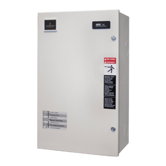
Series 185
Automatic Transfer Switches
Refer to the outline and wiring drawings provided with
your ASCO Series 185 ATS for all installation details.
ASCO Series 185 Automatic Transfer Switches (ATSs) are
Listed under Underwriter's Laboratories Standard for
Transfer Switch Equipment, UL–1008. They are intended
for use only in optional standby systems in accordance with
the National Electrical Code, NEC/NFPA 70, Article 702.
This ATS is for use with 2–wire automatic–start generators
only.
Refer to Application Information 381339–292 to confirm
that you have selected the appropriate product for the
intended installation.
This automatic transfer switch is intended for standby
power applications in residential / light commercial use
only.
This product is not intended for emergency
or life–support systems.
If you have more stringent application requirements contact
ASCO Power Technologies for other products suitable for
critical applications.
Each automatic transfer switch contains a rating label to
define the loads and fault circuit withstand / closing ratings.
Refer to the label on the transfer switch for specific values.
Do not exceed the values on the rating label.
Exceeding the rating can cause personal
injury or serious equipment damage.
TABLE OF CONTENTS
SEQUENCE OF OPERATION
. . . . . . . . . . . . . . . . . . . . . . . . . . . . . . . . .
Rating Label
. . . . . . . . . . . . . . . . . . . . . . . . . .
. . . . . . . . . . . . . . . . . . . . . . . .
. . . . . . . . . . . . . . . . . . . . . .
. . . . . . . . . . . . .
. . . . . . . . . . . . . . . . . .
381333–319 D
page
1
2–5
6
7
8–9
10
Advertisement
Table of Contents

Related Manuals for Emerson ASCO 185 Series


Summary of Contents for Emerson ASCO 185 Series
- Page 1 Series 185 Operator’s Automatic Transfer Switches Manual 100 through 400 ampere sizes Refer to the outline and wiring drawings provided with your ASCO Series 185 ATS for all installation details. DANGER is used in this manual to warn of high voltages capable of causing shock, burns, or death.
- Page 2 Series 185 Nameplate Catalog Number Identification The Transfer Switch nameplate includes data for A typical Catalog Number is shown below with its each specific ASCO Series 185 ATS. Use the ATS elements explained. The example is for a D–design, only within the limits shown on this nameplate. 2 pole, 200 A, 220–240 V , in Type 1 indoor enclosure: D 185 Neutral...
- Page 3 INSTALLATION Series 185 Installation of the ASCO Series 185 automatic transfer 2 --- Electrical Power Connections switch (ATS) must be performed by a licensed electrician. It must be installed according to the National Electrical Code (NEC) and all local electrical code requirements. Refer to the wiring diagram.
-
Page 4: Indicator Lights
CONTROLLER Series 185 The Group 4 digital Controller is used in ASCO Series 1 --- Push Buttons 185 automatic transfer switches. It provides the sensing, timing, and control functions for the ATS. This micro– On the front control display are three push buttons that processor–based controller includes built–in control control the operation of the generator and the ATS. - Page 5 CONTROLLER (continued) Series 185 3 --- Generator Starting Contacts 5 --- Automatic Generator Exerciser The generator starting contacts connections are on the The built–in automatic generator exerciser can be set to controller. Refer to the generator manual. Disconnect exercise the generator for 20 minutes once every week. the generator battery and verify that the ignition switch is in the OFF position.
- Page 6 CONTROLLER (continued) Series 185 S3 DIP switch S1 DIP switch S2 DIP switch Figure 6. DIP switches S1 and S2 at the top right. The time delay settings are shown in Figures 6 and 7 and in Table C. The sensor settings are shown in Figure 6 and in Table D.
- Page 7 CONTROLLER (continued) Series 185 6 --- Remote Control Features 7 --- Factory Settings --- Summary These remote control features require a customer– Table H. Factory Settings – Summary supplied normally–closed contact suitable for a 5 V dc DIP Switch DIP Actuator Actuator Position low energy circuit.
-
Page 8: Manual Operation
FUNCTIONAL TEST Series 185 After installing the Series 185 automatic transfer switch maintenance handle (ATS) perform the following three–part functional test. With ALL POWER OFF 1 --- Manual Operation grasp maintenance handle and turn it quickly with your A handle is provided on the transfer switch for thumb and fingers. - Page 9 Sequence of Operation --- Utility Failure Series 185 light is on light is off ¡ generator Utility power good. stops Utility fails Electrical loads on utility (longer than generator runs utility acceptable 3 sec.) unloaded for 2 min. load on utility ¥...
- Page 10 TROUBLESHOOTING Series 185 This troubleshooting guide describes some of the simple causes of problems with the installation of the automatic transfer switch. Troubleshooting beyond the scope of this guide should not be attempted by the installer. A licensed ELECTROCUTION FLASH HAZARD Do not work electrician must perform all internal troubleshooting.
- Page 11 TROUBLESHOOTING Series 185 (continued) Problem Cause and Solution The ATS does not immediately 1. Verify that the Generator Acceptable light is on. If it is off, see previous trouble- transfer the load to the shooting problem. The ATS will not transfer the load to an unacceptable source. generator.
- Page 12 INDEX Series 185 Automatic Generator Exerciser, 2, 3, handle, maintenance, 6 service, warning, 6 800–800–2726 (ASCO) customercare@asco.com harness, inside cover Set Engine Exerciser, button, 2, 3 HELP 800–800–2726 (ASCO) settings battery, clock, 3 customercare@asco.com changing, 3---5 buttons, push, 2 factory, 3---5 frequency, 3, 4 Bypass Time Delay, button, 2, 6 phase, 4...
Need help?
Do you have a question about the ASCO 185 Series and is the answer not in the manual?
Questions and answers