Table of Contents
Advertisement
Quick Links
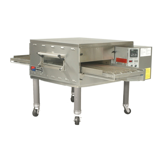
PS536GS
Gas
Domestic, Std. Export & CE
ENGLISH/French/Spanish
PS536GS Gas Ovens
Models:
•
PS536GS Gas
OWNER'S OPERATING, INSTALLATION,
AND PARTS MANUAL
for domestic, standard export and CE export ovens
© 2003 Middleby Marshall, Inc.
is a registered trademark of Middleby Marshall, Inc. All rights reserved.
Middleby Cooking Systems Group • 1400 Toastmaster Drive • Elgin, IL 60120 • (847)741-3300 • FAX (847)741-4406
Combinations:
•
Single Oven
•
Double Oven (Two-Stack)
•
Triple Oven (Three-Stack)
P/N 50236
Rev. B • V1 • 10/04
Price $30.00
Advertisement
Table of Contents

Subscribe to Our Youtube Channel
Related Manuals for Middleby Marshall PS536GS


Summary of Contents for Middleby Marshall PS536GS
- Page 1 CE export ovens © 2003 Middleby Marshall, Inc. is a registered trademark of Middleby Marshall, Inc. All rights reserved. Middleby Cooking Systems Group • 1400 Toastmaster Drive • Elgin, IL 60120 • (847)741-3300 • FAX (847)741-4406...
- Page 2 NOTICE: CONTACT YOUR MIDDLEBY MARSHALL AUTHORIZED SERVICE AGENT TO PERFORM MAINTENANCE AND REPAIRS. AN AUTHORIZED SERVICE AGENCY DIRECTORY IS SUPPLIED WITH YOUR OVEN. NOTICE: Using any parts other than genuine Middleby Marshall factory manufactured parts relieves the manufacturer of all warranty and liability.
-
Page 3: Table Of Contents
TABLE OF CONTENTS page page SECTION 1 - DESCRIPTION ........... 4 Connection ............13 OVEN USES ............. 4 GAS SUPPLY ............14 OVEN COMPONENTS ..........4 Gas Utility Rough-In Recommendations ..14 Window ............. 4 Gas Conversion ..........14 Conveyor End Stop ........... 4 C. -
Page 4: I. Oven Uses
SECTION 1 - DESCRIPTION OVEN USES Conveyor: Moves the food product through the oven. Not Shown: PS536GS ovens can be used to bake and/or cook a wide variety of food products, such as pizza, pizza-type products, Gas Burner: Heats air, which is then projected to the air cookies, sandwiches and others. - Page 5 SECTION 1 - DESCRIPTION Table 1-3: Electrical specifications for gas ovens (per oven cavity) Main Blower Control Current Voltage Circuit Voltage Phase Freq. Draw Poles Wires 208/240V 120V conv. speed control 1 Ph 50/60 Hz 6A * 2 Pole 3 Wire (2 hot, 1 gnd) &...
-
Page 6: Section 2 - Installation
SECTION 2 - INSTALLATION WARNING - For gas ovens, after any conversions, readjustments, or service work on the oven: • Perform a gas leak test. • Test for correct air supply. • Test for proper combustion and gas supply. • Check that the ventilation system is in operation. -
Page 7: I. Installation Kit
SECTION 2 - INSTALLATION Figure 2-1 - Installation Kit 4a, 4b, 4c, 4d INSTALLATION KIT - see Figure 2-1 Qty. Qty. Qty. Inc. with Inc. with Single Double Triple domestic Item Oven Oven Oven Part No. ovens? ovens? Description 48605 Top panel 3A80A8801 Screw, pan head #10 x 2″... -
Page 8: Ii. Ventilation System
SECTION 2 - INSTALLATION II. VENTILATION SYSTEM Recommendations NOTE THAT THE HOOD DIMENSIONS SHOWN IN FIGURE 2- 2 ARE RECOMMENDATIONS ONLY. LOCAL, NATIONAL AND IMPORTANT INTERNATIONAL CODES MUST BE FOLLOWED WHEN INSTALLING THE VENTILATION SYSTEM. ANY APPLICABLE Where national or local codes require the CODES SUPERSEDE THE RECOMMENDATIONS SHOWN IN THIS MANUAL. -
Page 9: A. Top Panel And Base Pad Assembly
SECTION 2 - INSTALLATION III. ASSEMBLY Figure 2-3 - Leg extension and casters installation Top Panel and Base Pad Assembly Finished sides of Install the four leg extensions onto the base pad using the leg extension 3/8"-16x1" screws, 3/8" flat washers, and 3/8" lockwashers face corner of supplied in the Base Pad Kit. -
Page 10: B. Stacking
PS536 Stacking Hardware Kit, P/N 46494 For triple ovens, repeat Step 1 to install the top oven cavity. Contact your Middleby Marshall Authorized Service Agent for Install the top panel using the screws included in the base pad complete stacking instructions. -
Page 11: D. Conveyor Installation
SECTION 2 - INSTALLATION Conveyor Installation Figure 2-9 - Conveyor installation Unfold the conveyor as shown in Figure 2-9. Then, begin to slide the conveyor into the end of the oven. The conveyor can only be installed from the end of the oven with the drive motor. -
Page 12: E. Final Assembly
SECTION 2 - INSTALLATION If it is necessary to add or remove conveyor links to achieve Final Assembly the correct tension, OR if it is necessary to reverse the Install the drive chain between the conveyor drive sprocket conveyor belt for correct orientation, the belt will need to be and the motor sprocket. -
Page 13: A. Additional Information - Gas Ovens
SECTION 2 - INSTALLATION IV. ELECTRICAL SUPPLY WARNING The oven requires a ground connection to the oven ground Authorized supplier personnel normally accomplish screw located in the electrical junction box. (The box is shown the connections for the ventilation system, electric supply, in Figure 2-14.) The ground connection must comply with all and gas supply, as arranged by the customer. -
Page 14: V. Gas Supply
Valve CAUTION The terms of the oven's warranty require all start-ups, conver- Individual gas sions and service work to be performed by a Middleby Marshall Flexible connection for Quick- Authorized Service Agent. The installation, start-up and changes Gas Hose... - Page 15 SECTION 2 - INSTALLATION Checking the Gas Supply (Inlet) Pressure Volumetric Method With the main gas supply valve closed and the circuit Determine the time of 0.1m (100 liters) of gas usage breaker/fused disconnect in the OFF ("O") position, open as follows.
-
Page 16: Section 3 - Operation
SECTION 3 - OPERATION LOCATION AND DESCRIPTION OF CONTROLS "BLOWER" Switch: Turns the blowers and Digital Temperature Controller: Continuously cooling fans on and off. The HEAT Switch has monitors the oven temperature. Settings on the no effect unless the BLOWER Switch is in the Digital Temperture Controller control the activa- “ON”... -
Page 17: Ii. Normal Operation, Step-By-Step
SECTION 3 - OPERATION II. NORMAL OPERATION - STEP-BY-STEP Wait for the oven to heat to the setpoint temperature. Higher setpoint temperatures will require a longer wait. The oven DAILY STARTUP PROCEDURE can reach a temperature of 500°F (232°C) in approximately 5 minutes. -
Page 18: Iii. Quick Reference: Digital Temperature Controller
SECTION 3 - OPERATION III. QUICK REFERENCE: DIGITAL TEMPERATURE CONTROLLER Display "HEAT ON" Shows the Set Point Light or the Actual Tem- Lights when the perature in degrees burner is in Fahrenheit (F) or operation. Celsius (C). "SP LOCK" Light Lights when the "SET PT"... -
Page 19: Section 4 - Maintenance
NOTE ANY replacement parts that require access to the interior of the oven may ONLY be replaced by a Middleby Marshall Authorized Service Agent. It is also strongly recommended that the 3-Month Maintenance and 6-Month Maintenance procedures in this section be performed ONLY by a Middleby Marshall Authorized Service Agent. -
Page 20: Ii. Maintenance - Monthly
SECTION 4 - MAINTENANCE II. MAINTENANCE - MONTHLY Figure 4-2 - Removing Air Fingers and Plates Check that the oven is cool and the power is disconnected, as described in the warning at the beginning of this Section. Refer to Part D, Conveyor Installation, in the Installation section of this Manual. - Page 21 SECTION 4 - MAINTENANCE Remove the master links from each conveyor belt. Figure 4-4 - Disassembling the idler shaft Then, roll the belts up along the length of the conveyor to remove them from the frame. Remove the two conveyor adjustment screws from the idler end of the conveyor frame, as shown in Figure 4- Disassemble, clean, and...
-
Page 22: Iv. Maintenance - Every 6 Months
Blower Belt Figure 4-7 - Rear panel access Remove the six screws shown in Figure 4-7. Then, remove the rear panel from the oven. Check the blower belt for the proper 1/4" (6mm) deflec- tion at the center, and for cracking or excessive wear. See Figure 4-7. -
Page 23: Section 5 - Parts List
SECTION 5 - PARTS LIST SECTION 5 - PARTS LIST I. KEY SPARE PARTS KIT ITEM QTY. DESCRIPTION 47321 DIGITAL TEMPERATURE CONTROLLER 51067 CONVEYOR DRIVE MOTOR W/PICKUP ASSY. 30153 DRIVE MOTOR BRUSHES 37337 KIT, CONVEYOR SPEED CONTROLER 33984 KIT, THERMOCOUPLE 6″ 50517 BELT, BLOWER 44687... - Page 25 SECTION 5 - PARTS LIST...
- Page 27 SECTION 5 - PARTS LIST...
- Page 29 SECTION 5 - PARTS LIST...
- Page 31 SECTION 5 - PARTS LIST...
- Page 33 SECTION 5 - PARTS LIST...
- Page 35 SECTION 5 - PARTS LIST...
- Page 37 SECTION 5 - PARTS LIST...
- Page 38 NOTES...
-
Page 39: Section 6 - Electrical Wiring Diagrams
SECTION 6 - ELECTRICAL WIRING DIAGRAMS SECTION 6 - ELECTRICAL WIRING DIAGRAMS Fig. 6-1 - Wiring diagram, PS536GS Gas Oven 208/240V, 50/60 Hz, 1 Ph IMPORTANT An electrical wiring diagram for the oven is also located inside the machinery compartment. - Page 40 Fig. 6-2 - Wiring diagram, PS536GS Gas Oven 208/240V, 50/60 Hz, 1 Ph...
- Page 41 SECTION 6 - ELECTRICAL WIRING DIAGRAMS Fig. 6-3 - Wiring diagram, PS536GS Gas Oven 208/240V, 50/60 Hz, 1 Ph...
- Page 42 NOTES...
- Page 43 NOTES...
- Page 44 NOTICE During the warranty period, ALL parts replacement and servicing should be performed by your Middleby Marshall Authorized Service Agent. Service that is performed by parties other than your Middleby Marshall Authorized Service Agent may void your warranty. NOTICE Using any parts other than genuine Middleby Marshall factory manufactured parts relieves the manufacturer of all warranty and liability.
Need help?
Do you have a question about the PS536GS and is the answer not in the manual?
Questions and answers