Table of Contents
Advertisement
Quick Links
Download this manual
See also:
Installation Manual
PS536GS
Gas
Domestic, Std. Export & CE
ENGLISH/French/Spanish
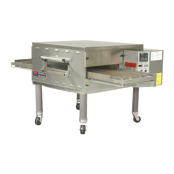
PS536GS Gas Ovens
Models:
•
PS536GS Gas
OWNER'S OPERATING, INSTALLATION,
AND PARTS MANUAL
for domestic, standard export and CE export ovens
© 2003 Middleby Marshall, Inc.
is a registered trademark of Middleby Marshall, Inc. All rights reserved.
Middleby Cooking Systems Group • 1400 Toastmaster Drive • Elgin, IL 60120 • (847)741-3300 • FAX (847)741-4406
Combinations:
•
Single Oven
•
Double Oven (Two-Stack)
•
Triple Oven (Three-Stack)
P/N 50236
Rev. B • V1 • 10/04
Price $30.00
Advertisement
Table of Contents

Subscribe to Our Youtube Channel
Related Manuals for Middleby Marshall PS536GS


Summary of Contents for Middleby Marshall PS536GS
- Page 1 PS536GS P/N 50236 Rev. B • V1 • 10/04 Domestic, Std. Export & CE Price $30.00 ENGLISH/French/Spanish PS536GS Gas Ovens Models: Combinations: • PS536GS Gas • Single Oven • Double Oven (Two-Stack) • Triple Oven (Three-Stack) OWNER'S OPERATING, INSTALLATION, AND PARTS MANUAL for domestic, standard export and CE export ovens ©...
- Page 2 NOTICE: This Owner's Operating and Installation Manual should be given to the user. The operator of the oven should be familiar with the functions and operation of the oven. This manual must be kept in a prominent, easily reachable location near the oven. Ovens are shipped from the factory configured for use with natural gas.
-
Page 3: Table Of Contents
VIII. SPLIT-BELT CONVEYORS ........37 C. Restraint Cable Installation ......10 SECTION 6 - ELECTRICAL WIRING DIAGRAMS ....39 D. Conveyor Installation ........11 WIRING DIAGRAM, PS536GS GAS OVEN Final Assembly ..........12 (DOMESTIC & STD. EXPORT VERSION), IV. ELECTRICAL SUPPLY ........... 13 208/240V, 50/60 Hz, 1 Ph ........ -
Page 4: I. Oven Uses
Conveyor: Moves the food product through the oven. Not Shown: PS536GS ovens can be used to bake and/or cook a wide variety of food products, such as pizza, pizza-type products, Gas Burner: Heats air, which is then projected to the air cookies, sandwiches and others. - Page 5 SECTION 1 - DESCRIPTION Table 1-3: Electrical specifications for gas ovens (per oven cavity) Main Blower Control Current Voltage Circuit Voltage Phase Freq. Draw Poles Wires 208/240V 120V conv. speed control 1 Ph 50/60 Hz 6A * 2 Pole 3 Wire (2 hot, 1 gnd) &...
-
Page 6: Section 2 - Installation
SECTION 2 - INSTALLATION WARNING - For gas ovens, after any conversions, readjustments, or service work on the oven: • Perform a gas leak test. • Test for correct air supply. • Test for proper combustion and gas supply. • Check that the ventilation system is in operation. -
Page 7: I. Installation Kit
SECTION 2 - INSTALLATION Figure 2-1 - Installation Kit 4a, 4b, 4c, 4d INSTALLATION KIT - see Figure 2-1 Qty. Qty. Qty. Inc. with Inc. with Single Double Triple domestic Item Oven Oven Oven Part No. ovens? ovens? Description 48605 Top panel 3A80A8801 Screw, pan head #10 x 2″... -
Page 8: Ii. Ventilation System
SECTION 2 - INSTALLATION II. VENTILATION SYSTEM Recommendations NOTE THAT THE HOOD DIMENSIONS SHOWN IN FIGURE 2- 2 ARE RECOMMENDATIONS ONLY. LOCAL, NATIONAL AND IMPORTANT INTERNATIONAL CODES MUST BE FOLLOWED WHEN INSTALLING THE VENTILATION SYSTEM. ANY APPLICABLE Where national or local codes require the CODES SUPERSEDE THE RECOMMENDATIONS SHOWN IN THIS MANUAL. -
Page 9: A. Top Panel And Base Pad Assembly
SECTION 2 - INSTALLATION III. ASSEMBLY Figure 2-3 - Leg extension and casters installation Top Panel and Base Pad Assembly Finished sides of Install the four leg extensions onto the base pad using the leg extension 3/8"-16x1" screws, 3/8" flat washers, and 3/8" lockwashers face corner of supplied in the Base Pad Kit. -
Page 10: B. Stacking
All four sides of the lower lip (on the bottom edge of the Installation. oven cavity) overlap the top of the lower oven. IMPORTANT • The oven is level. Middleby Marshall STRONGLY RECOMMENDS that PS536GS • The oven is firmly seated. oven cavities be stacked using the following: See Figure 2-6. •... -
Page 11: D. Conveyor Installation
SECTION 2 - INSTALLATION Conveyor Installation Figure 2-9 - Conveyor installation Unfold the conveyor as shown in Figure 2-9. Then, begin to slide the conveyor into the end of the oven. The conveyor can only be installed from the end of the oven with the drive motor. -
Page 12: E. Final Assembly
SECTION 2 - INSTALLATION If it is necessary to add or remove conveyor links to achieve Final Assembly the correct tension, OR if it is necessary to reverse the Install the drive chain between the conveyor drive sprocket conveyor belt for correct orientation, the belt will need to be and the motor sprocket. -
Page 13: A. Additional Information - Gas Ovens
SECTION 2 - INSTALLATION IV. ELECTRICAL SUPPLY WARNING The oven requires a ground connection to the oven ground Authorized supplier personnel normally accomplish screw located in the electrical junction box. (The box is shown the connections for the ventilation system, electric supply, in Figure 2-14.) The ground connection must comply with all and gas supply, as arranged by the customer. -
Page 14: V. Gas Supply
SECTION 2 - INSTALLATION NOTE: Certain safety code requirements exist for the installation V. GAS SUPPLY of gas ovens; refer to the beginning of Section 2 for a list of the installation standards. In addition: CAUTION • In the USA, the installation must conform with local codes, DURING PRESSURE TESTING NOTE THE FOLLOWING: or in the absence of local codes, with the National Fuel Gas 1. - Page 15 SECTION 2 - INSTALLATION Checking the Gas Supply (Inlet) Pressure Volumetric Method With the main gas supply valve closed and the circuit Determine the time of 0.1m (100 liters) of gas usage breaker/fused disconnect in the OFF ("O") position, open as follows.
-
Page 16: Section 3 - Operation
SECTION 3 - OPERATION LOCATION AND DESCRIPTION OF CONTROLS "BLOWER" Switch: Turns the blowers and Digital Temperature Controller: Continuously cooling fans on and off. The HEAT Switch has monitors the oven temperature. Settings on the no effect unless the BLOWER Switch is in the Digital Temperture Controller control the activa- “ON”... -
Page 17: Ii. Normal Operation, Step-By-Step
SECTION 3 - OPERATION II. NORMAL OPERATION - STEP-BY-STEP Wait for the oven to heat to the setpoint temperature. Higher setpoint temperatures will require a longer wait. The oven DAILY STARTUP PROCEDURE can reach a temperature of 500°F (232°C) in approximately 5 minutes. -
Page 18: Iii. Quick Reference: Digital Temperature Controller
SECTION 3 - OPERATION III. QUICK REFERENCE: DIGITAL TEMPERATURE CONTROLLER Display "HEAT ON" Shows the Set Point Light or the Actual Tem- Lights when the perature in degrees burner is in Fahrenheit (F) or operation. Celsius (C). "SP LOCK" Light Lights when the "SET PT"... -
Page 19: Section 4 - Maintenance
SECTION 4 - MAINTENANCE WARNING Before ANY cleaning or servicing of the oven, perform the following procedure: Switch off the oven and allow it to cool. Do NOT service the oven while it is warm. Turn the full-flow gas safety valve to the off position. Turn off the electric supply circuit breaker(s) and disconnect the electric supply to the oven. -
Page 20: Ii. Maintenance - Monthly
SECTION 4 - MAINTENANCE II. MAINTENANCE - MONTHLY Figure 4-2 - Removing Air Fingers and Plates Check that the oven is cool and the power is disconnected, as described in the warning at the beginning of this Section. Refer to Part D, Conveyor Installation, in the Installation section of this Manual. - Page 21 SECTION 4 - MAINTENANCE Remove the master links from each conveyor belt. Figure 4-4 - Disassembling the idler shaft Then, roll the belts up along the length of the conveyor to remove them from the frame. Remove the two conveyor adjustment screws from the idler end of the conveyor frame, as shown in Figure 4- Disassemble, clean, and...
-
Page 22: Iv. Maintenance - Every 6 Months
Blower Belt Figure 4-7 - Rear panel access Remove the six screws shown in Figure 4-7. Then, remove the rear panel from the oven. Check the blower belt for the proper 1/4" (6mm) deflec- tion at the center, and for cracking or excessive wear. See Figure 4-7. -
Page 23: Section 5 - Parts List
SECTION 5 - PARTS LIST SECTION 5 - PARTS LIST I. KEY SPARE PARTS KIT ITEM QTY. DESCRIPTION 47321 DIGITAL TEMPERATURE CONTROLLER 51067 CONVEYOR DRIVE MOTOR W/PICKUP ASSY. 30153 DRIVE MOTOR BRUSHES 37337 KIT, CONVEYOR SPEED CONTROLER 33984 KIT, THERMOCOUPLE 6″ 50517 BELT, BLOWER 44687... -
Page 25: Ii. Installation Kit
II. INSTALLATION KIT QTY. QTY. QTY. ITEM SINGLE OVEN DOUBLE OVEN TRIPLEOVEN DESCRIPTION 48605 TOP PANEL 3A80A8801 SCREW, PAN HEAD #10 x 2" 42893 BASE PAD 42890 17-1/2" (445mm) LEG EXTENSION, FOR SINGLE AND DOUBLE OVENS 45360 20-1/2" (521mm) LEG EXTENSION, OPTIONAL 45329 25-1/2"... -
Page 27: Iii. Panels, End Plugs And Window
III. PANELS, END PLUGS AND WINDOW ITEM QTY. DESCRIPTION ITEM QTY. DESCRIPTION 50172 WINDOW SHROUD 47633 BACK WALL 22500-0021 NAMEPLATE, "MIDDLEBY MARSHALL" 36451 COOLING FAN 48437 HEAT GUARD PLATE 31497 FINGER GUARD, COOLING FAN 30927 BUMPER See pp. 36-39 CHAIN COVER, UPPER 48512 ASSEMBLY, WINDOW (INC. -
Page 29: Iv. Control Compartment
IV. CONTROL COMPARTMENT QTY. QTY. QTY. QTY. ITEM SINGLE BELT SPLIT BELT DESCRIPTION ITEM SINGLE BELT SPLIT BELT DESCRIPTION 47321 DIGITAL TEMPERATURE 35145 RESET SWITCH, HIGH LIMIT CONTROLLER 31504 TRANSFORMER, 230V PRI : 120V 48511 DECAL, CONTROL PANEL SEC, 200VA 37337 KIT, CONVEYOR SPEED CON- 37498... -
Page 31: V. Machinery Compartment And Gas Train
V. MACHINERY COMPARTMENT AND GAS TRAIN ITEM QTY. DESCRIPTION ITEM QTY. DESCRIPTION 27470-0004 FINGER GUARD 44984 ORIFICE, MAIN, NATURAL GAS 0.0935" (2.3749mm, #42 DRILL) NOTE: The oven does NOT have a cooling fan in this location. The opening provides passive 47320 ORIFICE, MAIN, PROPANE 0.0595"... -
Page 33: Vi. Rear Compartment And Blowers
VI. REAR COMPARTMENT AND BLOWERS ITEM QTY. DESCRIPTION ITEM QTY. DESCRIPTION 42951 INLET RING A11687 SCREW, HEX CAP HEAD 5/16"-18 X 7/8" 42752 BLOWER WHEEL, RIGHT (VIEWED FROM B301A8847 FLAT WASHER, 5/16" REAR OF OVEN) A3682 LOCK WASHER, 5/16" 42753 BLOWER WHEEL, LEFT (VIEWED FROM REAR 50256 KIT, RPM, (50/60Hz) CONTAINS SHEAVE... -
Page 35: Vii. Single-Belt Conveyors
VII. SINGLE-BELT CONVEYORS P/N - 60" P/N - 56" P/N - 76" P/N - 60" P/N - 56" P/N - 76" ITEM QTY. CONVEYOR CONVEYOR CONVEYOR DESCRIPTION ITEM QTY. CONVEYOR CONVEYOR CONVEYOR DESCRIPTION 48847 48847 48790 FRAME, DRIVE SIDE < - - - - 51067 - - - - >... -
Page 37: Viii. Split-Belt Conveyors
VIII. SPLIT-BELT CONVEYORS P/N - 60" P/N - 56" P/N - 76" P/N - 60" P/N - 56" P/N - 76" ITEM QTY. CONVEYOR CONVEYOR CONVEYOR DESCRIPTION ITEM QTY. CONVEYOR CONVEYOR CONVEYOR DESCRIPTION 48847 48847 48790 FRAME, DRIVE SIDE < - - - - 51067 - - - - >... - Page 38 NOTES...
-
Page 39: Section 6 - Electrical Wiring Diagrams
SECTION 6 - ELECTRICAL WIRING DIAGRAMS SECTION 6 - ELECTRICAL WIRING DIAGRAMS Fig. 6-1 - Wiring diagram, PS536GS Gas Oven 208/240V, 50/60 Hz, 1 Ph IMPORTANT An electrical wiring diagram for the oven is also located inside the machinery compartment. - Page 40 Fig. 6-2 - Wiring diagram, PS536GS Gas Oven 208/240V, 50/60 Hz, 1 Ph...
- Page 41 SECTION 6 - ELECTRICAL WIRING DIAGRAMS Fig. 6-3 - Wiring diagram, PS536GS Gas Oven 208/240V, 50/60 Hz, 1 Ph...
- Page 42 NOTES...
- Page 43 ESPAÑOL FRANÇAIS DEUTSCH ENGLISH página 85 page 57 seite 29 page 1...
- Page 44 WARNING Improper installation, adjustment, alteration, service or maintenance can cause property damage, injury or death. Read the installation, operating and maintenance instructions thoroughly before installing or servicing this equipment. NOTICE During the warranty period, ALL parts replacement and servicing should be performed by your Middleby Marshall Authorized Service Agent.
Need help?
Do you have a question about the PS536GS and is the answer not in the manual?
Questions and answers