Table of Contents
Troubleshooting

Subscribe to Our Youtube Channel
Related Manuals for Middleby Marshall PS528G


Summary of Contents for Middleby Marshall PS528G
- Page 1 PS528-Series Gas Ovens: English A MIDDLEBY COMPANY owner's operating & installation manual PS528-Series OVENS PS528 (Single) Model PS528G PS528 (Triple) PS528 (Double) Part No. 63935 Rev. C Inc. ©2012 Middleby Marshall Price $30.00 P: 04/12...
- Page 2 Installation section of this Manual. For domestic and standard export ovens, instructions are included in the Gas Conversion Kit. It is suggested to obtain a service contract with a Middleby Marshall Authorized Service Agent. WARNING POST, IN A PROMINENT LOCATION, THE EMERGENCY TELEPHONE NUMBER OF YOUR LOCAL GAS SUPPLIER AND INSTRUCTIONS TO BE FOLLOWED IN THE EVENT YOU SMELL GAS.
- Page 3 © 2012 - Middleby Marshall, A Middleby Company. The Middleby Marshall logo is a registered trademark of Middleby Marshall, A Middleby Company. Middleby Marshall Inc. • 1400 Toastmaster Drive • Elgin, Illinois 60120-9272 U.S.A. • (847) 741-3300 • FAX: (847) 741 4406...
-
Page 4: Table Of Contents
TABLE OF CONTENTS TABLE OF CONTENTS (Continued) Page Page SECTION 1 I. MODEL IDENTIFICATION ..........1 III. STEP-BY-STEP OPERATION ........22 SERIES PS528 GAS SPECIFICATIONS ......2 A. Startup Procedures ..........22 II. COMPONENT FUNCTION ..........4 Daily Startup ..............22 A. Conveyor Motor and Conveyor Belt ......4 Power Failure ..............22 B. -
Page 5: Model Identification
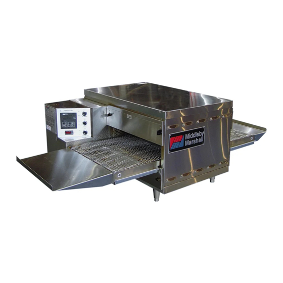
DESCRIPTION SECTION 1 DESCRIPTION I. MODEL IDENTIFICATION The Middleby Marshall PS528-Series may be used either as a single oven or stacked for use as double or triple ovens. A single PS528-Series Oven (Figure 1-1) is mounted on a base pad with legs. A double oven (Figure 1-2) consists of two, stacked, single ovens. -
Page 6: Series Ps528 Gas Specifications
SECTION 1 DESCRIPTION PS528 SERIES OVEN SPECIFICATIONS Conveyor Belt Width 18.00" (457mm) Heating Zone Length 28.00" (711mm) Baking Area Square Feet 3.5 sq. ft. (0.33 sq. m.) Overall Dimension Standard Single Oven w/Legs 50.00" (1270mm) L × 40.75" (1035mm) W × 21.72"... - Page 7 SECTION 1 DESCRIPTION II. COMPONENT FUNCTION (Figure 1-4) Figure 1-4. PS528-Series Oven Components Locations...
-
Page 8: Component Function
SECTION 1 DESCRIPTION II. COMPONENT FUNCTION A. Conveyor Motor and Conveyor Belt The conveyor belt is driven by a variable-speed electric motor (Figure 1-5) operating through a gear reducer. The motor speed is controlled by a digital control. The stainless-steel wire belt can travel in either direction at variable rates ranging from 3 minutes to 30 minutes;... - Page 9 SECTION 1 DESCRIPTION Figure 1-6. Cooling Fan...
- Page 10 SECTION 1 DESCRIPTION F2. Blank Plates 1. Blank Plates- The Blank Plates are available to install on the plenum where an air finger is not required. Figure 1-7. Blank Plates (two sizes) and an Air Finger.
-
Page 11: Section 2 Installation
SECTION 2 SECTION 2 INSTALLATION INSTALLATION WARNING - For gas ovens, after any conversions, readjustments, or service work on the oven: • Perform a gas leak test. • Test for correct air supply. • Test for proper combustion and gas supply. •... -
Page 12: Unloading
NOTE: The oven, when installed, must be electrically I. UNLOADING grounded in accordance with local codes, or in the absence Your Middleby Marshall PS528-Series Oven is shipped of local codes, with the National Electrical Code (NEC), partially assembled. It will arrive in a carton on a crate. - Page 13 SECTION 2 INSTALLATION PARTS LIST FOR SERIES PS528 Gas OVEN INSTALLATION KIT Double Stack Oven P/N 63947 ITEM NO. PART NO. DESCRIPTION 62208 INSULATION BOTTOM TRAY 62206 BOTTOM TRAY WELDMENT 61650 TOP COVER 51387 SCREW MSSLT THREAD 8-32 × 1/2, 18-8 3101908 LEG 4″...
- Page 14 SECTION 2 INSTALLATION Figure 2-5. MODEL PS528 SINGLE OVEN DIMENSIONS The Opening Height is Adjustable from 2-1/4 inch minimum to 3-3/4 inch maximum in 1/2 inch increments.
- Page 15 SECTION 2 INSTALLATION Figure 2-6. MODEL PS528 DOUBLE OVEN DIMENSIONS The Opening Height is Adjustable from 2-1/4 inch mini- mum to 3-3/4 inch maximum in 1/2 inch increments. P/N 59927 is shown in its correct installed position.
- Page 16 SECTION 2 INSTALLATION Figure 2-7. MODEL PS528 TRIPLE OVEN DIMENSIONS The Opening Height is Adjustable from 2-1/4 inch mini- mum to 3-3/4 inch maximum in 1/2 inch increments. P/N 59927 is shown in its correct installed position.
-
Page 17: Utility Rough-In Dimensions And Positioning For Ps528-Series Ovens
II. VENTILATION GUIDELINES Do NOT use conduit for ground. A mechanically driven ventilation system is required for the PS528 Series Middleby Marshall conveyorized gas ovens. DOMESTIC or EXPORT: 240V main blower motors, 1 Ph, 1.5 Amp draw, 50/60 Hz, 208-240V control circuit, 2 Local codes and conditions vary greatly from one area pole, 3 wire system per oven (2 hot, 1 grd). -
Page 18: Electrical Connection Information For Ps528-Series Ovens
SECTION 2 INSTALLATION III. ELECTRICAL CONNECTION IV. ELECTRIC SUPPLY FOR GAS HEATED INFORMATION FOR PS528-SERIES OVENS OVENS. Power requirements for gas heated ovens are 208 - 240VAC, 1-phase, 3-wire (2 ‘hot’, 1 ground). Electrical connection is made through a cord and plug. Using WARNING flexible cable(s) for the electrical power supply conductors Authorized supplier personnel normally accom-... -
Page 19: Gas Supply
SECTION 2 INSTALLATION V. GAS SUPPLY pressure tap of gas control concerned, to measure burner pressure (measuring point must be as near to burner as CAUTION possible). DURING PRESSURE TESTING NOTE THE FOLLOWING: ® Make sure that the appliance is in operation and the Moduplus coil is energized with maximum current. - Page 20 SECTION 2 INSTALLATION Figure 2-16. Gas Burner Assembly Maintenance Gas Burner It is recommended to check yearly the minimum and the maximum setting and readjust them if necessary. H. Connection WARNING Some procedures in this section may require conversions, readjustments, or service on the oven's gas system. Before performing these procedures, check that the main gas supply valve and the circuit breaker/fused disconnect are in the OFF ("O")
- Page 21 SECTION 2 INSTALLATION If the installation will use the supplied gas hose, be sure that the 1/2" to 3/4" gas line fitting is attached. Refer to the instructions in the gas hose package. One gas line connection method is shown in Figure 2-15; however, compliance with the applicable standards and regulations is mandatory. Inlet and regulated gas pressures can be measured using a “U”...
- Page 22 SECTION 2 INSTALLATION NOTES...
-
Page 23: Control Functions
SECTION 3 OPERATION SECTION 3 OPERATION I. CONTROL FUNCTIONS Figure 3-1. PS528-Series Oven Control Functions WARNING A possibility of injury from rotating parts and electric shock exists in this oven. Never disassemble or clean the oven with the BLOWER switch or any other oven control turned “ON”... -
Page 24: Component Information And Location
SECTION 3 OPERATION II. COMPONENT INFORMATION AND If the temperature inside the oven is over 180°F (82°C) the main blower will continue to run after the blower switch LOCATION (Figures 3-1 and 3-2) is turned to the “OFF” or “O” position. A. -
Page 25: Conveyor
SECTION 3 OPERATION E. Conveyor The on-off switch for the conveyor motor is on the con- trol panel. Also on the control panel is the digital con- veyor speed control. The digital control can be adjusted from 1-10 min. bake time (conveyor speed). Refer to Figure 3-3. -
Page 26: Step-By-Step Operation
SECTION 3 OPERATION 4. Set the temperature controller to the desired baking WARNING temperature. OVEN MUST BE KEPT CLEAR OF NOTE: For complete temperature controller operation COMBUSTIBLES AT ALL TIMES. instructions refer to Step C. 5. Turn the HEAT switch (Figure 3-6) to the “ON” or “I” III. - Page 27 SECTION 3 OPERATION Figure 3-6. Control Panel...
-
Page 28: Normal Operation - Step-By-Step
SECTION 3 OPERATION IV. NORMAL OPERATION - STEP-BY-STEP the setpoint temperature. Higher setpoint temperatures will require a longer wait. The oven can reach a temperature A.Daily Startup Procedure of 500°F (232°C) in approximately 15 minutes. Check that the circuit breaker/fused disconnect is in the (Optional) Press the Temperature ( ) key to show the Actual on position. - Page 29 SECTION 3 OPERATION Display "HEAT ON" Light Shows the Set Point Lights when the or the Actual Tem- burner is in perature in degrees operation. Fahrenheit (F) or Celsius (C). "SP LOCK" Light Lights when the set "SET PT" (set- point is locked out from changes.
-
Page 30: Quick Reference: Troubleshooting
Food products are over- Controls may be set incor- cooked or undercooked. rectly. IF THESE STEPS FAIL TO RESOLVE THE PROBLEM, CONTACT YOUR LOCAL MIDDLEBY MARSHALL AUTHORIZED SERVICE AGENT. A SERVICE AGENCY DIRECTORY IS SUPPLIED WITH YOUR OVEN. -
Page 31: Section 4 Maintenance
SECTION 4 MAINTENANCE SECTION 4 MAINTENANCE WARNING Before ANY cleaning or servicing of the oven, perform the following procedure: Switch off the oven and allow it to cool. Do NOT service the oven while it is warm. 2. Turn the full-flow gas safety valve to the off position. Turn off the electric supply circuit breaker(s) and disconnect the electric supply to the oven. If it is necessary to move a gas oven for cleaning or servicing, disconnect the gas supply before moving the oven. -
Page 32: Maintenance - Daily
SECTION 4 MAINTENANCE I. MAINTENANCE - DAILY D. Crumb Pans (Figure 4-2) A. Exterior WARNING Everyday you should clean the outside of the oven with a soft cloth and mild detergent. Crumb pan is extremely hot while oven is operating. Allow oven to cool before removing crumb pan. -
Page 33: Removing Conveyor From Oven For Cleaning
NOTE: The oven interior may require cleaning You can order non-caustic cleaner from your local more authorized Middleby Marshall Parts Distributor in the than once a month depending on the volume of baking. quantities listed: To clean the interior, you have to disassemble some... - Page 34 SECTION 4 MAINTENANCE side. 6. Remove conveyor as shown. Figure 4-6. Figure 4-4. Figure 4-7. Figure 4-5. CAUTION Be careful not to bump the drive sprocket while handling the conveyor, to avoid damaging the drive shaft.
-
Page 35: Air Fingers Disassembly For Cleaning
SECTION 4 MAINTENANCE B. Air Fingers Disassembly For Cleaning 1. As the air fingers are removed use a felt pen to mark all parts of the fingers. This includes the finger manifold, inner plate and the outer plate (refer to Figure 1-9). If a blank or choke plate is used, mark that plate also. -
Page 36: Reassembly Of Air Fingers
SECTION 4 MAINTENANCE 6. To remove the inner plate, pull the plate out and then up. C. Reassembly of Air Fingers 1. Air fingers are made up of one inner plate, one outer plate and the finger housing manifold. Be sure to match up the markings (T1, T2, T3, etc.) on all the parts of the air fingers as you are reassembling. - Page 37 SECTION 4 MAINTENANCE 4. Replace the air fingers by pushing in at the back side. Remember to replace them according to the numbers marked on them when they were removed. They must go back in the same way they came out. IMPORTANT: When inserting fingers the tab on the outer plate must be in the groove as shown in Figure 4-18.
- Page 38 SECTION 4 MAINTENANCE 5. Install fingers and blank plates correctly with edges interlocked and no space between edges. Incorrect - Too Top Finger Much Space Blank Plate Tab on Outer Plate of Finger Located in Groove Incorrect - Too Top Finger Much Space Blank Plate Tab on Outer Plate of Finger...
-
Page 39: Reinstall End Plugs
SECTION 4 MAINTENANCE D. Reinstall End Plugs 1. Reinstall lower end plug. Be sure to tighten the wing screw on the end plug. 2. Reinstall conveyor. 3. Reinstall upper end plug. Be sure to tighten two wing screws on the end plug. Figure 4-19. -
Page 40: Conveyor Reassembly Into Oven
SECTION 4 MAINTENANCE E. Conveyor Reassembly Into Oven F. Checking Conveyor Belt Tension 1. Lift conveyor and position it in oven as shown. WARNING NOTE: Conveyor may be inserted into either end of oven. Oven conveyor belt must be cool when adjusting If it is to be installed from the non-drive end of the oven belt. -
Page 41: Conveyor Belt Link Removal
SECTION 4 MAINTENANCE 1. Using long nose pliers, an entire link can be removed 4. Unhook the link to be removed. with the conveyor assembly either in or out of the oven. 5. Pull up on the belt link section and remove. Do not Position master links at end of conveyor as shown in discard the link removed as it may be used for making Figure 4-24. -
Page 42: Attaching Drive Chain
SECTION 4 MAINTENANCE 6. Reconnect the inside master links (Figure 4-29.) H. Attaching Drive Chain 1. If drive sprocket assembly was removed reassemble it into the conveyor drive shaft. Be sure flat on end of drive shaft aligns with set screw in conveyor shaft collar. Once in place tighten 3/32″... -
Page 43: Maintenance - Every 3 Months
A. Check brushes on D.C. conveyor motor, when worn to less than 1/10″ (2.4mm), replace the brushes. NOTE: It is recommended that the 3-month maintenance be performed by an authorized Middleby Marshall B. Check your oven venting system. technician. C. Inspect and clean the burner nozzle and the spark electrode assembly. -
Page 44: Ps528-Series Gas Oven Key Spare Parts
(Figure 4-36). (The kit can be purchased when the oven is ordered, or later, from a Middleby Marshall Authorized Replacement parts for this kit can be purchased from your Parts Distributor). The kit contains many of the crucial Middleby Marshall Authorized Parts Distributor. -
Page 45: Section 5 Troubleshooting
Turn temperature Start the oven again. If the oven still does not Set the conveyor speed control to correct control at correct setting. heat, call your Middleby Marshall Service Agency. setting. Verify the food prepa- PROBLEM: ration process. CONVEYOR WILL NOT HOLD PROPER SPEED... - Page 46 SECTION 5 TROUBLESHOOTING NOTES...
-
Page 47: Section 6 Electrical Schematics
SECTION 6 ELECTRICAL SCHEMATICS SECTION 6 ELECTRICAL SCHEMATICS... - Page 48 NOTICE During the warranty period, ALL parts replacement and servicing should be performed by your Middleby Marshall Authorized Service Agent. Service that is performed by par- ties other than your Middleby Marshall Authorized Service Agent may void your war- ranty.
Need help?
Do you have a question about the PS528G and is the answer not in the manual?
Questions and answers