Middleby Marshall PS536 Owner's Operating & Installation Manual
Gas and electric ovens
Hide thumbs
Also See for PS536:
- Owner's operating and installation manual (29 pages) ,
- Owner's operating and installation manual (84 pages)
Advertisement
Quick Links
PS536
Gas & Electric
Domestic & Std. Export
ENGLISH/French/Spanish
PS536 Gas and Electric Ovens
Models:
•
PS536
OWNER'S OPERATING
& INSTALLATION
MANUAL
© 2000 Middleby Marshall, Inc.
is a registered trademark of Middleby Marshall, Inc. All rights reserved.
Middleby Cooking Systems Group • 1400 Toastmaster Drive • Elgin, IL 60120 • (847)741-3300 • FAX (847)741-4406
Combinations:
•
Single Oven
•
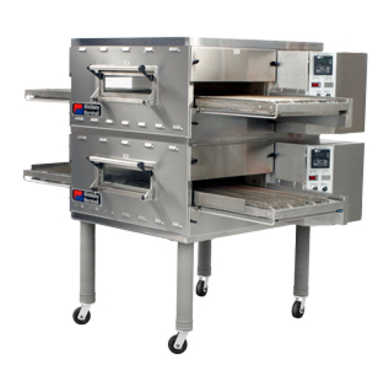
Double Oven (Two-Stack)
•
Triple Oven (Three-Stack)
1
P/N 44727
Rev. B • V1 • 11/00
Advertisement

Related Manuals for Middleby Marshall PS536


Summary of Contents for Middleby Marshall PS536
- Page 1 Triple Oven (Three-Stack) OWNER'S OPERATING & INSTALLATION MANUAL © 2000 Middleby Marshall, Inc. is a registered trademark of Middleby Marshall, Inc. All rights reserved. Middleby Cooking Systems Group • 1400 Toastmaster Drive • Elgin, IL 60120 • (847)741-3300 • FAX (847)741-4406...
- Page 2 NOTICE: CONTACT YOUR MIDDLEBY MARSHALL AUTHORIZED SERVICE AGENT TO PERFORM MAINTENANCE AND REPAIRS. AN AUTHORIZED SERVICE AGENCY DIRECTORY IS SUPPLIED WITH YOUR OVEN. NOTICE: Using any parts other than genuine Middleby Marshall factory manufactured parts relieves the manufacturer of all warranty and liability.
-
Page 3: Table Of Contents
TABLE OF CONTENTS page page SECTION 1 - DESCRIPTION ........... 4 SECTION 3 - OPERATION ............. 15 SECTION 2 - INSTALLATION ..........6 SECTION 4 - MAINTENANCE ..........19 SECTION 5 - ELECTRICAL WIRING DIAGRAMS ....23... -
Page 4: Section 1 - Description
SECTION 1 - DESCRIPTION OVEN USES Gas Burner (gas ovens) or Heating Elements (electric ovens): Blowers: II. OVEN COMPONENTS - see Figure 1-1. Window (on ovens so equipped): M. Air Fingers: Conveyor Exit Tray: Fig. 1-1 - Oven Components Eyebrows (on ovens so equipped): End Plugs: Control Panel: Machinery Compartment Access Panel:... - Page 5 SECTION 1 - DESCRIPTION Table 1-3: Electrical specifications for electric ovens (per oven cavity) Main Blower Control Current Voltage Circuit Voltage Phase Freq. Draw Rating Poles Wires 208V 120V conv. speed control, 3 Ph 60 Hz 50A at 208V 16.0 kW at 208V 4 Pole 4 Wire (3 hot, 1 gnd) drive motor, contactor,...
-
Page 6: Section 2 - Installation
SECTION 2 - INSTALLATION WARNING - For gas ovens, after any conversions, readjustments, or service work on the oven: • Perform a gas leak test. • Test for correct air supply. • Test for proper combustion and gas supply. • Check that the ventilation system is in operation. - Page 7 Caster, with flat plate (no brake) 21392-0004 Eyebolt, 3/4" 220373 Hex bolt, 3/8"-16 x 1" 21416-0001 Flat washer, 3/8" 21422-0001 Lockwasher, 3/8" 22450-0228 Restraint cable assembly 22361-0001 Gas hose 44727 Owner's Operating Manual, PS536 Gas and Electric Ovens 1002040 Middleby Marshall Authorized Service Agency Listing...
- Page 8 SECTION 2 - INSTALLATION II. VENTILATION SYSTEM Recommendations IMPORTANT Where national or local codes require the installation of fire suppression equip- ment or other supplementary equipment, DO NOT mount the equipment directly to the oven. MOUNTING SUCH EQUIPMENT ON THE OVEN MAY: •...
- Page 9 SECTION 2 - INSTALLATION III. ASSEMBLY Figure 2-3 - Leg extension and casters installation Finished sides of Top Panel and Base Pad Assembly leg extension face corner of base pad 3/8" flat washer 3/8" lock washer 3/8"-16 x 1" hex screw 3/4"...
- Page 10 SECTION 2 - INSTALLATION Stacking Figure 2-5 - Assembling the stacking spacers #10-32 x 1/2" hex screws 1-1/2" (38mm)-thick insulation, pre-cut Stacking panel, P/N 44837 Top panel, P/N 42882 Figure 2-6 - Stacking Assembled Insulation spacer faces up...
- Page 11 SECTION 2 - INSTALLATION Restraint Cable Installation Figure 2-7 - Installing the Restraint Cable Restraint cable assembly 3/8"-16 x 1" eyebolt on rear leg extension 3/4” (19mm) eyebolt Wall of structure Conveyor Installation Figure 2-8 - Assembling and tensioning the conveyor Slotted holes (2 per side) Install...
- Page 12 SECTION 2 - INSTALLATION Figure 2-10 - Conveyor placement Crumb tray support bracket End plug Figure 2-11 - Final assembly Chain cover: Place down over Wing screws conveyor sprocket 2 per end plug V. FINAL ASSEMBLY Conveyor exit tray: Press down over end of conveyor Crumb trays (2):...
- Page 13 SECTION 2 - INSTALLATION VI. ELECTRICAL SUPPLY Additional Information - Electric Ovens WARNING Authorized supplier personnel normally accomplish the connections for the ventilation system, electric supply, and gas supply, as arranged by the customer. Following these connections, the factory-authorized installer can perform the initial startup of the oven.
- Page 14 SECTION 2 - INSTALLATION Gas Utility Rough-In Recommendations Figure 2-14 - Flexible Gas Hose Installation 90° Elbow To Gas Supply Pipe Connection Union OR Full-Flow quick- disconnect Shutoff device Valve Flexible Gas Hose Figure 2-15 - Gas Burner and Piping Assembly NOTE In-shot Pilot...
-
Page 15: Section 3 - Operation
SECTION 3 - OPERATION LOCATION AND DESCRIPTION OF CONTROLS Fig. 3-1 - Control Panel "BLOWER" Switch: Conveyor Speed Controller: "HEAT" Switch: Digital Temperature Controller: "CONVEYOR" Switch: NOT SHOWN: Machinery Compartment Access Panel Safety Switch:... - Page 16 SECTION 3 - OPERATION II. NORMAL OPERATION - STEP-BY-STEP DAILY STARTUP PROCEDURE DAILY SHUTDOWN PROCEDURE IMPORTANT Actual temp temp CAUTION No attempt should be made to operate the oven during a power failure. In gas ovens, the burner will not operate and gas will not flow through the burner without electric power.
- Page 17 SECTION 3 - OPERATION III. QUICK REFERENCE: DIGITAL TEMPERATURE CONTROLLER light Illuminates when the burner or heating elements are on. This light will flicker during normal operation after the oven reaches the set point temperature. light Illuminates when Upper display oven temperature is Shows the actual EITHER below...
- Page 18 SECTION 3 - OPERATION IV. QUICK REFERENCE: TROUBLESHOOTING SYMPTOM PROBLEM SOLUTION IF THESE STEPS FAIL TO RESOLVE THE PROBLEM, CONTACT YOUR LOCAL MIDDLEBY MARSHALL AUTHORIZED SERVICE AGENT. A SERVICE AGENCY DIRECTORY IS SUPPLIED WITH YOUR OVEN.
-
Page 19: Section 4 - Maintenance
SECTION 4 - MAINTENANCE WARNING WARNING CAUTION NOTE I. MAINTENANCE - DAILY Figure 4-1 -Cooling Vents and Grills Vents on CAUTION front panel of oven Vents on rear of Grills/vents machinery on rear of compartment oven access panel... - Page 20 SECTION 4 - MAINTENANCE II. MAINTENANCE - MONTHLY Figure 4-2 - Removing Air Fingers and Plates Figure 4-3 - Disassembling the Air Fingers CAUTION Outer Plate Inner plate Manifold III. MAINTENANCE - EVERY 3 MONTHS Split Belt Disassembly and Cleaning...
- Page 21 SECTION 4 - MAINTENANCE Figure 4-5 - Disassembling the drive shaft Spacer (2) 2. Loosen set screws on belt sprockets and spacers (8) Smooth sprocket (2) Sprockets w/teeth (4) 1. Remove outer drive sprocket 3. Slide shafts out Bushing of frame 4.
- Page 22 SECTION 4 - MAINTENANCE Blower Belt Figure 4-6 - Rear panel access Remove six (6) screws to remove rear panel Lubricating the Blower Fan Bearings Bearings (2 total) Grease fitting (1 per bearing) Blower belt Blower motor Loosen four (4) screws to adjust IV.
-
Page 23: Section 5 - Electrical Wiring Diagrams
SECTION 5 - ELECTRICAL WIRING DIAGRAMS Fig. 5-1 - Wiring diagram, PS536 Gas Oven IMPORTANT An electrical wiring diagram for the oven is also located inside the machinery compartment. - Page 24 SECTION 5 - ELECTRICAL WIRING DIAGRAMS Fig. 5-2 - Wiring diagram, PS536 Electric Oven Middleby Cooking Systems Group • 1400 Toastmaster Drive • Elgin, IL 60120 • USA • (847)741-3300 • FAX (847)741-4406 24-Hour Service Hotline: 1-(800)-238-8444 www.middleby.com...
Need help?
Do you have a question about the PS536 and is the answer not in the manual?
Questions and answers