Middleby Marshall PS528-SERIES PS528G Owner's Operating And Installation Manual
Ps528-series gas ovens
Hide thumbs
Also See for PS528-SERIES PS528G:
- Owner's operating & installation manual (48 pages) ,
- Owner's operating & installation manual (60 pages)
Table of Contents
Troubleshooting

Related Manuals for Middleby Marshall PS528-SERIES PS528G


Summary of Contents for Middleby Marshall PS528-SERIES PS528G
- Page 1 PS528-Series Gas Ovens: English A MIDDLEBY COMPANY owner's operating & installation manual PS528-Series OVENS PS528 (Single) Model PS528G PS528 (Triple) PS528 (Double) Part No. 63935 Rev. B Inc. ©2009 Middleby Marshall Price $30.00 P: 08/09...
- Page 2 Installation section of this Manual. For domestic and standard export ovens, instructions are included in the Gas Conversion Kit. It is suggested to obtain a service contract with a Middleby Marshall Authorized Service Agent. POST, IN A PROMINENT LOCATION, THE EMERGENCY TELEPHONE NUMBER OF YOUR LOCAL GAS SUPPLIER AND INSTRUCTIONS TO BE FOLLOWED IN THE EVENT YOU SMELL GAS.
- Page 3 © 2009 - Middleby Marshall, A Middleby Company. The Middleby Marshall logo is a registered trademark of Middleby Marshall, A Middleby Company. Middleby Marshall Inc. • 1400 Toastmaster Drive • Elgin, Illinois 60120-9272 U.S.A. • (847) 741-3300 • FAX: (847) 741 4406 Serial No.
-
Page 4: Table Of Contents
Troubleshooting Charts ... 41 SECTION 6 ELECTRICAL SCHEMATICS Wiring Diagram, G208-240V 50/60 GO, PS528 ... 43 Wiring Diagrams are in Section 6 of this Manual. The diagram for each oven is also on the lower inner surface of its Control Console. (Continued) Page... -
Page 5: Model Identification
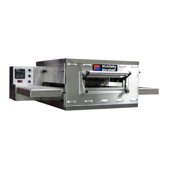
DESCRIPTION SECTION 1 DESCRIPTION I. MODEL IDENTIFICATION The Middleby Marshall PS528-Series may be used either as a single oven or stacked for use as double or triple ovens. A single PS528-Series Oven (Figure 1-1) is mounted on a base pad with legs. A double oven (Figure 1-2) consists of two, stacked, single ovens. -
Page 6: Series Ps528 Gas Specifications
SERIES PS528 ELECTRICAL SPECIFICATIONS Main Blower & Control Circuit Elements Voltage Voltage 208-240V 208-240V GAS ORIFICE AND PRESSURE SPECIFICATIONS (PER OVEN CAVITY) - DOMESTIC AND STANDARD ExPORT OVENS Gas Type Main Orifice I.D. Natural #42 drill (.094")(2.38mm) Propane #48 drill (.076")(1.93mm) * The gas supply pressures and orifice sizes shown are for ovens installed in North America. - Page 7 SECTION 1 DESCRIPTION II. COMPONENT FUNCTION (Figure 1-4) Figure 1-4. PS528-Series Oven Components Locations...
-
Page 8: Component Function
B. Blower Fan The blower fans are located at the rear of the oven. These blowers force heated air through the air fingers. The BLOWER switch must be set to “ON” or “I” for oven warmup and baking. C. Gas Burner The gas burner is located inside the rear panel and is controlled by the temperature controller. - Page 9 SECTION 1 DESCRIPTION Figure 1-6. Cooling Fan...
- Page 10 SECTION 1 DESCRIPTION Figure 1-7. Blank Plates (two sizes) and an Air Finger. F2. Blank Plates 1. Blank Plates- The Blank Plates are available to install on the plenum where an air finger is not required.
- Page 11 These casters are intended to simplify pre-installation movement only, and are NOT suitable for use as part of a CE oven installation. During the installation procedure, the casters MUST be removed, so that the oven can be supported by the supplied 152mm adjustable legs.
-
Page 12: Unloading
ITEM Figure 2-1. PS528-Series Gas Oven Installation Parts I. UNLOADING Your Middleby Marshall PS528-Series Oven is shipped partially assembled. It will arrive in a carton on a crate. The crate and carton must be examined before signing the Bill of Lading. Report any visible damage to the transport company, and check for the proper number of crates. - Page 13 M3828 22450-0228 22361-0001 49975 23115-0009 31823 59227 62207 Figure 2-1 (continued). PS528-Series Gas Oven Installation Parts DESCRIPTION INSULATION BOTTOM TRAY BOTTOM TRAY WELDMENT TOP COVER SCREW MSSLT THREAD 8-32 × 1/2, 18-8 LEG 4″ AD FT GAS HOSE RESTRAINT CABLE GAS HOSE CORD &...
- Page 14 SECTION 2 INSTALLATION Figure 2-5. MODEL PS528 SINGLE OVEN DIMENSIONS The Opening Height is Adjustable from 2-1/4 inch minimum to 3-3/4 inch maximum in 1/2 inch increments.
- Page 15 SECTION 2 INSTALLATION Figure 2-6. MODEL PS528 DOUBLE OVEN DIMENSIONS The Opening Height is Adjustable from 2-1/4 inch mini- mum to 3-3/4 inch maximum in 1/2 inch increments. P/N 59927 is shown in its correct installed position.
- Page 16 SECTION 2 INSTALLATION Figure 2-7. MODEL 528 TRIPLE OVEN DIMENSIONS The Opening Height is Adjustable from 2-1/4 inch mini- mum to 3-3/4 inch maximum in 1/2 inch increments. P/N 59927 is shown in its correct installed position.
-
Page 17: Utility Rough-In Dimensions And Positioning For Ps528-Series Ovens
INSTALLED OR WARRANTY WILL BE VOID. II. VENTILATION GUIDELINES A mechanically driven ventilation system is required for the PS528 Series Middleby Marshall conveyorized gas ovens. Local codes and conditions vary greatly from one area to another and must be complied with. Following are the suggested requirements for good ventilation. -
Page 18: Electrical Connection Information For Ps528-Series Ovens
Check the oven data plate (Figure 2-10) before making any electric supply connections. Electric supply connec- tions must agree with data on the oven data plate. NOTE: The electric supply installation must satisfy the requirements of the appropriate statutory authority, such as the National Electrical Code (NEC), ANSI/NFPA70, (U.S.A.);... -
Page 19: Gas Supply
V. GAS SUPPLY CAUTION DURING PRESSURE TESTING NOTE THE FOLLOWING: 1. The oven and its individual shutoff valve must be dis- connected from the gas supply piping system during any pressure testing of that system at test pressure in excess of 1/2 psi (3.45 kPa). -
Page 20: Section 2 Installation
After completing these procedures, perform a gas leak test before operating the oven. CAUTION The terms of the oven's warranty require all start-ups, conver- sions and service work to be performed by a Middleby Mar- shall Authorized Service Agent. The installation, start-up and changes required when changing from one gas type to another can be performed ONLY by a certified professional. -
Page 21: Installation Section
Manual. Adjust the temperature controller to the maximum setting (316°C). Measure the supply (inlet) pressure. Switch the oven off. Close the main gas supply valve, and switch the circuit breaker/fused disconnect to the OFF ("O") position. Remove the manometer, and close the inlet tap. - Page 22 SECTION 2 INSTALLATION NOTES...
-
Page 23: Control Functions
Never disassemble or clean the oven with the BLOWER switch or any other oven control turned “ON” or “I”. Turn “OFF” or “O” and lockout or tagout all electric power to the oven before attempting to clean or service this oven. -
Page 24: Component Information And Location
The blower switch has two positions. The switch must be “ON” or “I” for the main blowers to come on and permit the oven to run. The fan circulates the air throughout the oven and must stay on during baking and during the cool down cycle above 200°F (93°C) to prevent blower bearing... -
Page 25: Conveyor
This should be the conveyor speed shown on the con- veyor speed digital control. NOTE: In Figures 3-4 and 3-5, the oven shown is with the conveyor running right to left. WARNING Possibility of injury from rotating parts and electrical shock exist in this oven. -
Page 26: Step-By-Step Operation
“ON” or “I”. The cooling fans cool the control components and blower motor. The cooling fans, located at the rear of the oven blows air into and through the cabinet. Air is exhausted through the front of the cabinet and also out the front of the oven. - Page 27 SECTION 3 OPERATION Figure 3-6. Control Panel...
-
Page 28: Normal Operation - Step-By-Step
“OFF” or “O” position. IMPORTANT On gas ovens, if the "HEAT ON" light will not illuminate, OR if the oven does not heat, the gas burner may not have lit. Turn the "HEAT" ( ), "BLOWER" ) switches to the "OFF" ("O") position. Wait for AT LEAST FIVE MINUTES before restarting the oven. - Page 29 This setting can only be changed by service personnel. OVERTEMP Light Lights when the oven temperature is greater than 650°F (343°C). Refer to Quick Refer- ence: Troubleshoot- ing in this section. Temperature Key Press this key once...
-
Page 30: Quick Reference: Troubleshooting
Food products are over- Controls may be set incor- cooked or undercooked. rectly. IF THESE STEPS FAIL TO RESOLVE THE PROBLEM, CONTACT YOUR LOCAL MIDDLEBY MARSHALL AUTHORIZED SERVICE AGENT. A SERVICE AGENCY DIRECTORY IS SUPPLIED WITH YOUR OVEN. PROBLEM •... -
Page 31: Section 4 Maintenance
2. Turn the full-flow gas safety valve to the off position. Turn off the electric supply circuit breaker(s) and disconnect the electric supply to the oven. If it is necessary to move a gas oven for cleaning or servicing, disconnect the gas supply before moving the oven. When all cleaning and servicing is complete: If the oven was moved for servicing, return the oven to its original location. -
Page 32: Maintenance - Daily
Allow oven to cool before removing crumb pan. When the oven is cool remove and clean the crumb pan at each end of the oven. Each crumb pan can be removed by sliding it out, as shown in Figure 4-2. Reinstall the crumb pans after cleaning. -
Page 33: Removing Conveyor From Oven For Cleaning
For heavier cleaning of baked on grease and carbon deposits use a non-caustic cleaner that will not react with the aluminized finger manifold surfaces. You can order non-caustic cleaner from your local authorized Middleby Marshall Parts Distributor in the quantities listed: Part # 27170-0244... - Page 34 MAINTENANCE Figure 4-4. Figure 4-5. side. 6. Remove conveyor as shown. Figure 4-6. Figure 4-7. CAUTION Be careful not to bump the drive sprocket while handling the conveyor, to avoid damaging the drive shaft.
-
Page 35: Air Fingers Disassembly For Cleaning
Fingers are marked in the order shown; as viewed from the front of the oven. (The marks for an upper oven should be preceded with a “U”, example UB1, UT2, etc.) Standard Fingers 2. -
Page 36: Reassembly Of Air Fingers
MAINTENANCE 6. To remove the inner plate, pull the plate out and then up. Figure 4-11. 7. The outer finger plate is stainless and may be cleaned by either soaking in a hot, strong detergent solution or using a caustic cleaner. The conveyor belt can also be cleaned in the same way. - Page 37 4. Replace the air fingers by pushing in at the back side. Remember to replace them according to the numbers marked on them when they were removed. They must go back in the same way they came out. IMPORTANT: When inserting fingers the tab on the outer plate must be in the groove as shown in Figure 4-18.
- Page 38 MAINTENANCE 5. Install fingers and blank plates correctly with edges interlocked and no space between edges. Top Finger Tab on Outer Plate of Finger Located in Groove Top Finger Tab on Outer Plate of Finger Located in Groove Top Finger Tab on Outer Plate of Finger Located in Groove Incorrect - Too...
-
Page 39: Reinstall End Plugs
SECTION 4 MAINTENANCE D. Reinstall End Plugs 1. Reinstall lower end plug. Be sure to tighten the wing screw on the end plug. 2. Reinstall conveyor. 3. Reinstall upper end plug. Be sure to tighten two wing screws on the end plug. Figure 4-19. -
Page 40: Conveyor Reassembly Into Oven
1. Lift conveyor and position it in oven as shown. NOTE: Conveyor may be inserted into either end of oven. If it is to be installed from the non-drive end of the oven the drive sprocket assembly must be removed as shown in conveyor disassembly section. -
Page 41: Conveyor Belt Link Removal
1. Using long nose pliers, an entire link can be removed with the conveyor assembly either in or out of the oven. Position master links at end of conveyor as shown in Figure 4-24. Master Links Figure 4-24. 2. Using long nose pliers, unhook master links at left end of conveyor as shown in Figure 4-25. -
Page 42: Attaching Drive Chain
Direction of travel Figure 4-30. 7. Reconnect the outside master links. 8. Replace all parts removed from the oven. Figure 4-31. H. Attaching Drive Chain 1. If drive sprocket assembly was removed reassemble it into the conveyor drive shaft. -
Page 43: Maintenance - Every 3 Months
Shut OFF all electrical power and lock/tag out the switch before attempting maintenance work. NOTE: It is recommended that the 3-month maintenance be performed by an authorized Middleby Marshall technician. A. Electrical Terminals Open the control cabinet door by removing the three screws from the control cabinet door. -
Page 44: Ps528-Series Gas Oven Key Spare Parts
An oven can be purchased with a key Spare Parts kit (Figure 4-36). (The kit can be purchased when the oven is ordered, or later, from a Middleby Marshall Authorized Parts Distributor). The kit contains many of the crucial PS528-SERIES GAS OVEN KEY SPARE PARTS KIT (Figure 4-36) ITEM PART NO. -
Page 45: Section 5 Troubleshooting
OVEN BLOWER AND CONVEYOR OPERATE, YET THE OVEN IS NOT HEATING Start the oven again. If the oven still does not heat, call your Middleby Marshall Service Agency. setting. CONVEYOR WILL NOT HOLD PROPER SPEED Check for proper tension of conveyor drive chain and conveyor belt. - Page 46 SECTION 5 TROUBLESHOOTING NOTES...
-
Page 47: Section 6 Electrical Schematics
SECTION 6 ELECTRICAL SCHEMATICS SECTION 6 ELECTRICAL SCHEMATICS... - Page 48 During the warranty period, ALL parts replacement and servicing should be performed by your Middleby Marshall Authorized Service Agent. Service that is performed by par- ties other than your Middleby Marshall Authorized Service Agent may void your war- Using any parts other than genuine Middleby Marshall factory manufactured parts re- lieves the manufacturer of all warranty and liability.
Need help?
Do you have a question about the PS528-SERIES PS528G and is the answer not in the manual?
Questions and answers