Table of Contents
Advertisement
Quick Links
Download this manual
See also:
User Manual
Advertisement
Table of Contents

Subscribe to Our Youtube Channel
Related Manuals for Lightspeed CAT 860


Summary of Contents for Lightspeed CAT 860
- Page 1 CAT 860 Classroom Audio System U s e r M a n u a l...
-
Page 2: Table Of Contents
TABLE OF CONTENTS SECTION 1: Important Safety Instructions Overview System Components and Unpacking Optional Components CAT 860 Front Panel Controls CAT 860 Rear Panel Controls Infrared Sensor / Receiver (ISR) Connections REDMIKE Controls and Connections Cradle Charger Controls and Connections SECTION 2: Step 1. - Page 3 TABLE OF CONTENTS CONT’D TABLE OF CONTENTS CONT’D 14. RS-232 Serial Interface Command Definition 7. Differentially Decrease Volume for Selected Basic Command Set for Audio Switcher Audio Output Command Operations 8. Set Absolute Volume for Selected Audio Audio Input Functions for the A/V Source Output Command Group 9.
-
Page 4: Important Safety Instructions
IMPORTANT SAFETY INSTRUCTIONS 1. Read these instructions. 11. Only use attachments/ accessories specified by the manufacturer. 2. Keep these instructions. 12. Use only with a cart, stand, tripod, 3. Heed all warnings. bracket or table specified by the 4. Follow all instructions. manufacturer, or sold with the apparatus. -
Page 5: System Components And Unpacking
SECTION 1: Speakers and Speaker Wire Systems can be configured with a variety of different speaker types, OVERVIEW including the following: WMQ (x 4) SYSTEM COMPONENTS AND UNPACKING The standard configuration of the CAT 860 will contain: DRQ (x 4) CAT 860 Amplifier NXQ (x 1) Amplifier Power... -
Page 6: Optional Components
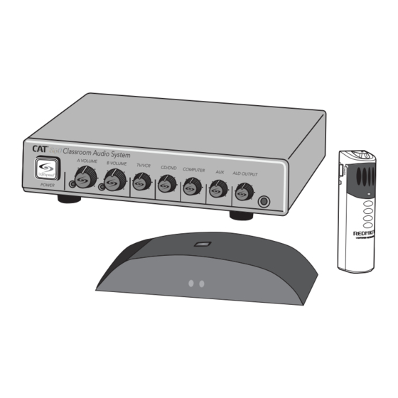
OPTIONAL COMPONENTS FRONT PANEL CONTROLS Optional equipment which may be part of your CAT 860 system: REDMIKE® VC Volume Control Microphone REDMIKE Share Handheld Mic & Charger Cable 1. POWER SWITCH/INDICATOR: 6. ALD OUTPUT AND VOLUME: Press this button to turn the CAT This jack sends mixed audio to 860 ON (pushed in) or OFF. -
Page 7: Infrared Sensor/Receiver (Isr) Connections
REAR PANEL CONTROLS INFRARED SENSOR/RECEIVER (ISR) CONNECTIONS Front Panel RS-232 Control Select RS-232 IN RS-232 Control Select RS-232 IN 1. CONTROL SELECT: Both adjust the sensitivity if needed. microphone and aux input volume 7. EQUALIZER (4-BAND): Adjust can be adjusted from the front these controls upon installation to panel controls or remotely from properly equalize the system to... -
Page 8: Redmike Controls And Connections
REDMIKE CONTROLS AND CONNECTIONS CRADLE CHARGER CONTROLS AND CONNECTIONS 1. POWER BUTTON: Press this opening the compartment door, as 1. CHARGE INDICATORS: The light 2. DC POWER PORT: Connect the button to turn the REDMIKE ON, it may tear, leaving fragments. glows RED while the REDMIKE is DC power cord here. -
Page 9: Step 1. Location Of The Amplifier
SECTION 2: 2. IR SENSOR/RECEIVER (ISR) INSTALLATION SET-UP & USE Next, find a suitable location for the ISR. Poor location will cause substandard performance of the CAT 860 Classroom Audio System. The ISR should be as high as possible in the room – the ceiling is the best location, centered along the longest wall in the room. - Page 10 2. IR SENSOR/RECEIVER (ISR) INSTALLATION 2. IR SENSOR/RECEIVER (ISR) INSTALLATION CONT’D CONT’D Once you find a suitable location for the ISR, follow these instructions to mount Wall/Solid Ceiling Mount it. There are different instructions for mounting depending on if the ISR will be mounted to a suspended ceiling grid or secured to a wall / solid vertical surface.
-
Page 11: Step 3. Installation Of Amplifier Wall-Mount Bracket
3. INSTALLATION OF AMPLIFIER WALL- 5A. CONNECT THE POWER SUPPLY MOUNT BRACKET 1. Ensure the power button is 3. Connect the black AC power cable depressed in the OFF position. from the power supply to a wall The CAT 860 systems include a bracket for optional wall-mounting. outlet. -
Page 12: Step 6. Audio Integration
5C. SPEAKER CONNECTION(S) 6. AUDIO INTEGRATION Next, connect the CAT 860 to the speakers. Then, be sure any auxiliary audio The next step in setting up your CAT 860 system is to connect it to the other sources are connected to the corresponding labeled input on the CAT 860. multimedia devices in your classroom. -
Page 13: Step 7. Charging The Redmike
Lightspeed rechargeable sensing battery. Replacement AA NiMH batteries the collarbone. NOTE: Positioning may only be purchased through Lightspeed Technologies (part # BA-NH2A27). of the REDMIKE is critical for Do not attempt to charge alkaline batteries. They can overheat and expand proper volume adjustment. -
Page 14: 26 9. Audio Equalization Of The Cat 860
9. AUDIO EQUALIZATION OF THE CAT 860 10. OUTPUT TO PERSONAL ASSISTIVE LISTENING DEVICE (ALD) The CAT 860 uses a 4-band audio equalizer designed to optimize and fine-tune the microphone sound quality for the classroom. Below are some tips on proper system equalization: 1. -
Page 15: Using The Redmike To Amplify External Audio Equipment
11. USING THE REDMIKE TO AMPLIFY 12. PAGEFIRST: PRIORITY MUTE EXTERNAL AUDIO EQUIPMENT This optional feature interfaces with an independent classroom paging system. When the page is broadcast, all audio from the system is muted, ensuring important school-wide messages are never missed. The REDMIKE includes a 3.5mm audio input jack to connect to an audio source like a laptop or MP3 player. -
Page 16: Rs-232 Serial Interface Programming
13. RS-232 SERIAL INTERFACE 13. RS-232 SERIAL INTERFACE PROGRAMMING PROGRAMMING CONT’D The CAT 860 uses standard RS-232 protocols as a serial link to an external Connector Signal Wiring control module such as an intelligent wall panel, or a personal computer. When the Control Select switch in the “RS-232”... -
Page 17: Summary Of Command & Response Transactions
13. RS-232 SERIAL INTERFACE 13. RS-232 SERIAL INTERFACE PROGRAMMING PROGRAMMING CONT’D CONT’D Summary of command and response transactions: Summary of command and response transactions Cont’d: 1. Action Command Functions for the Basic Command Set (Audio Switcher f. Return Absolute Audio Output Channel Volume Setting Operations): g. -
Page 18: Control Character Hex Value And Definition
13. RS-232 SERIAL INTERFACE 13. RS-232 SERIAL INTERFACE PROGRAMMING PROGRAMMING CONT’D CONT’D Control Character Hex Value and Definition (0x02) Start character of an action command packet. General Format for Query Command Exchange: (0x04) End character of any command packet. (0x06) Only response character from the CAT 860 In this example the external controller sends query command packet to CAT if action command (PING command only) is... -
Page 19: Basic Command Set For Audio Switcher Operations
14. RS-232 SERIAL INTERFACE 14. RS-232 SERIAL INTERFACE COMMAND DEFINITION COMMAND DEFINITION CONT’D BASIC COMMAND SET FOR AUDIO SWITCHER OPERATIONS BASIC COMMAND SET FOR AUDIO SWITCHER OPERATIONS CONT’D Audio Input Functions for the A/V Source Group Cont’d Audio Input Functions for the A/V Source Group 2. -
Page 20: Decrement Audio/Video Sources Command
14. RS-232 SERIAL INTERFACE 14. RS-232 SERIAL INTERFACE COMMAND DEFINITION COMMAND DEFINITION CONT’D CONT’D BASIC COMMAND SET FOR AUDIO SWITCHER OPERATIONS CONT’D BASIC COMMAND SET FOR AUDIO SWITCHER OPERATIONS CONT’D Audio Input Functions for the A/V Source Group Cont’d Audio Input Functions for the A/V Source Group Cont’d 3. -
Page 21: Mute Audio/Video Sources Command
14. RS-232 SERIAL INTERFACE 14. RS-232 SERIAL INTERFACE COMMAND DEFINITION COMMAND DEFINITION CONT’D CONT’D BASIC COMMAND SET FOR AUDIO SWITCHER OPERATIONS CONT’D BASIC COMMAND SET FOR AUDIO SWITCHER OPERATIONS CONT’D Audio Input Functions for the A/V Source Group Cont’d Audio Input Functions for the A/V Source Group Cont’d 5. -
Page 22: Mute Microphone Audio Inputs Command
14. RS-232 SERIAL INTERFACE 14. RS-232 SERIAL INTERFACE COMMAND DEFINITION COMMAND DEFINITION CONT’D CONT’D BASIC COMMAND SET FOR AUDIO SWITCHER OPERATIONS CONT’D BASIC COMMAND SET FOR AUDIO SWITCHER OPERATIONS CONT’D Audio Input Functions for the A/V Source Group Cont’d Audio Input Functions for the A/V Source Group Cont’d 7. -
Page 23: Toggle Mute For Microphone Audio Inputs Command
14. RS-232 SERIAL INTERFACE 13. RS-232 SERIAL INTERFACE COMMAND DEFINITION PROGRAMMING CONT’D CONT’D BASIC COMMAND SET FOR AUDIO SWITCHER OPERATIONS CONT’D BASIC COMMAND SET FOR AUDIO SWITCHER OPERATIONS CONT’D Audio Input Functions for the A/V Source Group Cont’d Audio Input Functions for the A/V Source Group Cont’d 10. -
Page 24: Query Absolute Volume Audio/Video Source Command
13. RS-232 SERIAL INTERFACE 14. RS-232 SERIAL INTERFACE PROGRAMMING COMMAND DEFINITION CONT’D CONT’D BASIC COMMAND SET FOR AUDIO SWITCHER OPERATIONS CONT’D BASIC COMMAND SET FOR AUDIO SWITCHER OPERATIONS CONT’D Audio Input Functions for the A/V Source Group Cont’d Audio Input Functions for the A/V Source Group Cont’d 12. -
Page 25: 14. Query Mute For Audio/Video Source Command
14. RS-232 SERIAL INTERFACE 14. RS-232 SERIAL INTERFACE COMMAND DEFINITION COMMAND DEFINITION CONT’D CONT’D BASIC COMMAND SET FOR AUDIO SWITCHER OPERATIONS CONT’D BASIC COMMAND SET FOR AUDIO SWITCHER OPERATIONS CONT’D Audio Input Functions for the A/V Source Group Cont’d Audio Input Functions for the A/V Source Group Cont’d 14. -
Page 26: Advanced Command Set For Audio Mixer Operations
14. RS-232 SERIAL INTERFACE 14. RS-232 SERIAL INTERFACE COMMAND DEFINITION COMMAND DEFINITION CONT’D CONT’D ADVANCED COMMAND SET FOR AUDIO MIXER OPERATIONS ADVANCED COMMAND SET FOR AUDIO MIXER OPERATIONS CONT’D Audio Input Functions for the A/V Source Group Audio Input Functions for the A/V Source Group Cont’d 1. -
Page 27: Differentially Increase Volume For Selected Audio Input Command
14. RS-232 SERIAL INTERFACE 14. RS-232 SERIAL INTERFACE COMMAND DEFINITION COMMAND DEFINITION CONT’D CONT’D ADVANCED COMMAND SET FOR AUDIO MIXER OPERATIONS CONT’D ADVANCED COMMAND SET FOR AUDIO MIXER OPERATIONS CONT’D Audio Input Functions for the A/V Source Group Cont’d Audio Input Functions for the A/V Source Group 1. -
Page 28: Set Absolute Volume For Selected Audio Input Command
14. RS-232 SERIAL INTERFACE 14. RS-232 SERIAL INTERFACE COMMAND DEFINITION COMMAND DEFINITION CONT’D CONT’D ADVANCED COMMAND SET FOR AUDIO MIXER OPERATIONS CONT’D ADVANCED COMMAND SET FOR AUDIO MIXER OPERATIONS CONT’D Audio Input Functions for the A/V Source Group Cont’d Audio Input Functions for the A/V Source Group Cont’d 3. -
Page 29: Select Audio Output Command
14. RS-232 SERIAL INTERFACE 14. RS-232 SERIAL INTERFACE COMMAND DEFINITION COMMAND DEFINITION CONT’D CONT’D ADVANCED COMMAND SET FOR AUDIO MIXER OPERATIONS CONT’D ADVANCED COMMAND SET FOR AUDIO MIXER OPERATIONS CONT’D Audio Input Functions for the A/V Source Group Cont’d Audio Input Functions for the A/V Source Group Cont’d 5. -
Page 30: Differentially Decrease Volume For Selected Audio Output Command
14. RS-232 SERIAL INTERFACE 14. RS-232 SERIAL INTERFACE COMMAND DEFINITION COMMAND DEFINITION CONT’D CONT’D ADVANCED COMMAND SET FOR AUDIO MIXER OPERATIONS CONT’D ADVANCED COMMAND SET FOR AUDIO MIXER OPERATIONS CONT’D Audio Input Functions for the A/V Source Group Cont’d Audio Input Functions for the A/V Source Group Cont’d 7. -
Page 31: Query Absolute Volume For Selected Audio Output Command
14. RS-232 SERIAL INTERFACE 14. RS-232 SERIAL INTERFACE COMMAND DEFINITION COMMAND DEFINITION CONT’D CONT’D ADVANCED COMMAND SET FOR AUDIO MIXER OPERATIONS CONT’D ADVANCED COMMAND SET FOR AUDIO MIXER OPERATIONS CONT’D Audio Input Functions for the Infrared Source Group Audio Input Functions for the A/V Source Group Cont’d 9. -
Page 32: Differentially Increase Volume For Selected Infrared Input Command
14. RS-232 SERIAL INTERFACE 14. RS-232 SERIAL INTERFACE COMMAND DEFINITION COMMAND DEFINITION CONT’D CONT’D ADVANCED COMMAND SET FOR AUDIO MIXER OPERATIONS CONT’D ADVANCED COMMAND SET FOR AUDIO MIXER OPERATIONS CONT’D Audio Input Functions for the Infrared Source Group Cont’d Audio Input Functions for the Infrared Source Group Cont’d 2. -
Page 33: Set Absolute Volume For Selected Infrared Input Command
14. RS-232 SERIAL INTERFACE 14. RS-232 SERIAL INTERFACE COMMAND DEFINITION COMMAND DEFINITION CONT’D CONT’D ADVANCED COMMAND SET FOR AUDIO MIXER OPERATIONS CONT’D ADVANCED COMMAND SET FOR AUDIO MIXER OPERATIONS CONT’D Audio Input Functions for the Infrared Source Group Cont’d Audio Input Functions for the Infrared Source Group Cont’d 4. -
Page 34: Input Muting Functions Group
14. RS-232 SERIAL INTERFACE 14. RS-232 SERIAL INTERFACE COMMAND DEFINITION COMMAND DEFINITION CONT’D CONT’D ADVANCED COMMAND SET FOR AUDIO MIXER OPERATIONS CONT’D ADVANCED COMMAND SET FOR AUDIO MIXER OPERATIONS CONT’D Input Muting Functions Group Input Muting Functions Group Cont’d 1. MUTE SELECTED AUDIO INPUT COMMAND 2. -
Page 35: System Management Functions Group
14. RS-232 SERIAL INTERFACE 13. RS-232 SERIAL INTERFACE COMMAND DEFINITION PROGRAMMING CONT’D CONT’D ADVANCED COMMAND SET FOR AUDIO MIXER OPERATIONS CONT’D System Management Functions Group <CMD> <Param> Value Definition 1. QUERY MODEL AND SOFTWARE VERSION COMMAND Symbol Value Audio Input Functions <CMD>... -
Page 36: Optional Accessories
13. RS-232 SERIAL INTERFACE SECTION 3: PROGRAMMING OPTIONAL ACCESSORIES CONT’D OPTIONAL REDMIKE VC (Volume Control) <CMD> <Param> Value Definition Symbol Value Controls and Connections Audio Input Functions MREV? 0xC0 Controller sends no param Query model and value. software version. (Param string in response packet will be composed of up to sixteen ACSII alphanumeric... - Page 37 REDMIKE VC : Charging OPTIONAL LT-71: Controls and Connections Before use, the REDMIKE VC should be charged. See page 20 and follow the same instructions for the REDMIKE. REDMIKE VC : Initial Set-up LT-71 LT-71 See page 17 and follow the same instructions for the REDMIKE to setup the REDMIKE VC.
- Page 38 LT-71: Charging LT-71: Initial Set-up 1. Ensure that the LT-71 is turned OFF. Once the LT-71 is charged, follow these steps to set it up for use. 2. Make sure the cradle charger is plugged into a wall outlet. Connect one end of the charging cable into the jack labeled 1.
-
Page 39: Redmike Share: Controls And Connections
REDMIKE Share: Controls and Connections REDMIKE Share: Charging 1. Ensure that the REDMIKE Share is 3. Plug the other end into the turned OFF. charging jack on the rear of the cradle charger. 2. Make sure the cradle charger is plugged into a wall outlet. 4. -
Page 40: Initial Set-Up
REDMIKE Share: Initial Set-up INITIAL SET-UP: OPTIONAL IR MEDIA CONNECTOR 1. Ensure the CAT 860 is ON. The RED LED on the power switch will 1. Turn off the second microphone. glow. The iR Media Connector uses 2. Turn on the REDMIKE Share by the same channel (channel B) as sliding the switch to the top the optional second microphone... -
Page 41: Other Optional Accessories
OPTIONAL IR MEDIA CONNECTOR AUDIO SECTION 4: INTEGRATION TROUBLESHOOTING The iRMC is designed to integrate with the CAT 860 and multiple audio sources, allowing other instructional technologies to be clearly heard throughout the classroom. COMMON PROBLEMS AND SOLUTIONS Video In Projector Projector Note: Most problems are directly related to low battery power. -
Page 42: Tips To Obtain Optimal Audio Performance
Repair by other than Lightspeed or its authorized service agencies will void this guarantee. Information on authorized service agencies is available from Lightspeed Technologies, Inc. Our Service Department (800.732.8999, 5 a.m. – 5 p.m., PST) will handle all your... -
Page 43: Safety Warnings And Certifications
European Union Directives: 89/336/EEC, 92/31/EEC, 93/68/ EED, and 2004/108/EC Electromagnetic Compatibility Directives. Lightspeed Technologies launched a formal product recycle program in Europe that complies with the European Union Directive 2002/96/EC on Waste Electrical and Electronic Equipment (“WEEE Directive”). Please visit our website at www.Lightspeed-tek.com for more... -
Page 44: System Specifications
SYSTEM SPECIFICATIONS OVERALL SPECIFICATIONS Power Output 12 W per channel (24 W total) Amplifier Frequency Response 60 Hz to 20 kHz ±3 dB Carrier Frequencies (IR) 2.06/2.54; 3.2/3.7 MHz Signal-to-Noise Ratio > 73 dB Image and Spurious Rejection > 70 dB AMPLIFIER SPECIFICATIONS Receiver Type Superheterodyne... - Page 45 LIGHTSPEE D TE CHNOLOGIES 1 1509 SW HERMAN RO AD / TUAL ATI N, OR 970 62 TOL L F REE: 800.732 .89 99 / PHO NE: 503.68 4.5 538 / FAX: 503.684.3197 LIG HTSPEE D-TEK. COM MN0258US01-3...
Need help?
Do you have a question about the CAT 860 and is the answer not in the manual?
Questions and answers