Table of Contents
Advertisement
Advertisement
Table of Contents

Related Manuals for Motorola RDM series MURS


Summary of Contents for Motorola RDM series MURS
- Page 1 RDM Series MURS Two-Way Radios User Guide...
-
Page 3: Table Of Contents
Getting Started ..... 24 CONTENTS Turning radio ON/OFF ....24 Adjusting volume . - Page 4 Battery Type Settings Frequency Selection ....39 (RDM2080d Model) ....32 CTSS/DPL Codes .
- Page 5 Troubleshooting .....58 Motorola Limited Warranty for the United States and Canada ..62 Accessories .
-
Page 6: Safety
For a list of Motorola-approved, batteries, and SAFETY other accessories, visit the following website: www.motorola.com/RDX PRODUCT SAFETY AND RF EXPOSURE COMPLIANCE Before using this product, read the RF energy awareness information and operating instructions in the Product Safety and RF... -
Page 7: Batteries And Chargers
Use of accessories not recommended by available. Disassembly of the charger Motorola may result in risk of fire, electric may result in risk of electrical shock or shock, or injury. fire. - Page 8 To reduce risk of electric shock, unplug • The outlet to which this equipment is the charger from the AC outlet before connected should be nearby and easily attempting any maintenance or cleaning accessible. OPERATIONAL SAFETY GUIDELINES • Maximum ambient temperature around the power supply equipment must not exceed •...
-
Page 9: Introduction
Thank you for purchasing the Motorola® RDM 8000 West Sunrise Boulevard Series MURS Two-Way Radio. This radio is a Plantation, Florida 33322 product of Motorola's more than 75 years of experience as a world leader in the designing PACKAGE CONTENTS and manufacturing of communications •... - Page 10 For a copy of a large-print version of this user 1-866-522-5210 on your TTY (Text guide or for product-related questions, contact: Telephone) 1-800-448-6686 in the USA For product information visit us at: www.motorola.com/business 1-800-461-4575 in Canada This User Guide covers the following RDM Series models: Frequency Transmit Number of...
-
Page 11: Fcc Licensing
Motorola may void the user’s FCC LICENSING authority granted by the FCC to operate this INFORMATION radio and should not be made. To comply with FCC requirements, transmitter adjustments REGULATION ON MURS (MULTI-USE should be made only by or under the... -
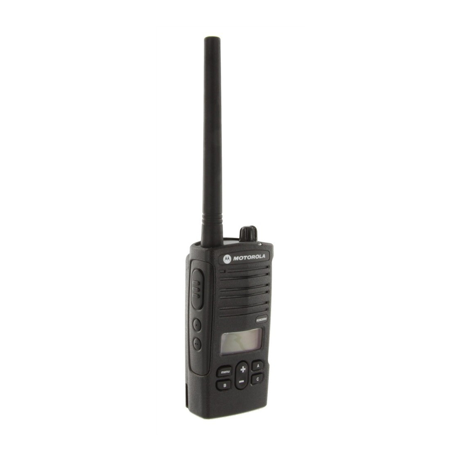
Page 12: Radio Overview
RADIO OVERVIEW DISPLAY MODEL – RDM2080d Fixed Lithium-Ion On/Off/ Antenna Battery Volume Knob LED Indicator Accessory Microphone Connector PTT (Push-to-Talk) Button Model Label SB1 – Monitor Menu Button/ Button to scroll up/ Keypad Lock down through channels and menu setting SB2 –... -
Page 13: Non-Display Model - Rdm2020
NON-DISPLAY MODEL – RDM2020 Fixed Channel Selector Antenna Knob Lithium-Ion On/Off/Volume Battery Knob Microphone PTT (Push-to-Talk) LED Indicator Button SB1 – Monitor Button Accessory Connector Model Label SB2 – Nuisance Channel Delete English... - Page 14 On/Off/Volume Knob Front Buttons (RDM2080d Model Only) Used to turn the radio ON or OFF and to adjust the radio’s volume. Channel Selector Knob Used to switch the radio to different channels. Accessory Connector Used to connect compatible audio accessories. Microphone •...
- Page 15 Configurable Buttons Scan / Channel Channel Button Monitor Nuisance Call Tone Scramble Backlight No Operation Preset 1 Preset 2 Delete Default Default BUTTON A (*) Default BUTTON B (*) Default BUTTON C (*) Default Buttons are configured to default functions, other features may be assigned to these buttons as shown in the table.
- Page 16 Icons Chart (RDM2080d Model) Icon Symbol Comments Battery Level Displayed during normal radio mode operation, displays battery life remaining. Channel Displayed during normal radio operation and when programming channel features. Code Displayed during normal radio operation and when programming codes features. Frequency Displayed during normal radio operation.
-
Page 17: Battery Features
Motorola batteries are designed specifically to disposed of in landfills or incinerators. Contact be used with a Motorola charger and vice your local waste management agency for versa. Charging in non-Motorola equipment specific requirements and information in your may lead to battery damage and void the area. -
Page 18: Drop-In Tray Charger And Power Supply
Many retailers and dealers participate in this DROP-IN TRAY CHARGER AND POWER program. For the location of the drop-off facility SUPPLY closest to you, access RBRC's Internet web site at: http://www.call2recycle.org/ or call: 1-800-8-BATTERY Power Supply This internet site and telephone number also provides other useful information concerning Drop-in Tray Charger recycling options for consumers, businesses... -
Page 19: Installing The Battery
Turn OFF the radio. Turn OFF the radio. With the Motorola logo side up, fit the tabs at Push down and hold the battery latch. the bottom of the battery into the slots at the Pull the top of the battery out and lift it from the bottom of the radio. - Page 20 Alkaline Battery Pack (Optional) Installing Alkaline Batteries Removing Alkaline Batteries Alkaline Alkaline Battery Battery Door Door Turn OFF the radio and remove the Li-Ion Turn OFF the radio and remove the battery door battery. on the battery frame. Assemble alkaline battery frame in the same Remove the five AA alkaline batteries from the steps as installing the Li-Ion battery.
- Page 21 Li-Ion Battery Life When the Battery Save feature is ON (enabled by default) the battery life will be longer. The following chart summarizes battery life estimations: Li-Ion Battery Life with Battery Save feature ON Battery Type 2 Watts Standard 12 hours High 24 hours Ultra High...
- Page 22 Alkaline Battery Life The following chart estimates the Alkaline battery life: Alkaline Battery Life Battery Save Feature 2 Watts 26 hours Note: Battery life is estimated based on the following standard duty cycle: 5% Transmit, 5% Receive and 90% Standby. English...
- Page 23 Battery Meter (RDM2080d Model) The battery meter located in the upper left corner of the display model indicates the remaining battery power. RDM Series Battery Meter 3 Bars 2 Bars 1 Bar Battery Type Li-Ion 100% – 70% 70% – 30% 30% –...
-
Page 24: Charging The Battery
(Transformer) The RDM radio comes equipped with a Standard Charger. Use only use Motorola-approved Drop-in Tray Single Unit Charger or Drop-in Tray Multi Unit Drop-in Tray Charger Port Charger to charge the Motorola-approved battery. - Page 25 Adjustable bracket with slots on the bottom with slots on the top To charge a stand alone Motorola battery, follow steps 1 to 3 in the previous section and insert the battery into the tray, with the inside surface of the battery facing the front of the charger.
- Page 26 Charging a High Capacity or Ultra High To adjust the charger to accommodate the High Capacity Battery capacity or Ultra High capacity battery: The bracket in the charger must be adjusted to Squeeze both tabs on each side of the the correct position for either Standard or High removable bracket in the drop-in charger tray capacity battery.
- Page 27 Drop-in Tray Charger LED Indicators Standard Charger LED Indicator Status LED Status Comments Power ON Steady red for 3 seconds The charger has powered up Charging Blinking red (slow) The charger is currently charging Charging Steady red Battery is fully charged Complete Battery Fault(*) Blinking red (fast)
- Page 28 Rapid Charger LED Indicator Status LED Status Comments Power ON Steady green for 3 seconds The charger has powered up Charging Blinking green The charger is currently charging Top-off Charging Blinking green (slow) Battery is near fully charged Charge Steady green Battery is fully charged Complete Battery Fault (*)
- Page 29 Estimated Charging Time The following table provides the estimated charging time of the battery. For further details, see "Battery” on page 66. Estimated Charging Time Battery Type Charging Solution Ultra High Standard High Capacity Capacity Standard Charging 7 hours 12 hours 13 hours Solution Rapid Charging...
- Page 30 Charging Batteries using a Multi Unit Charger- MUC (Optional) MUC LED Indicator Status LED Status Comments Steady Red The charger is Charging Indication currently charging Charge Steady Green Battery is fully Complete Indication charged Battery Blinking red Battery was faulty The Multi Unit Charger (MUC) allows drop-in Fault (*) (fast)
-
Page 31: Installing Spring Action
INSTALLING SPRING ACTION BELT CLIP Belt Clip Spring Action Belt Clip Slide the spring action belt clip rails into the belt clip grooves on the back of the battery and slide it down until the belt clip tab snaps into place. To remove, pull back the metal release tab on the belt clip tab and push the spring action belt clip upward to remove. -
Page 32: Getting Started
READING THE DISPLAY (RDM2080d GETTING STARTED MODEL) TURNING RADIO ON/OFF Keypad Hi Power Lock Turn the On/Off/Volume knob clockwise to turn Repeater/Talkaround Vox / Scramble ON the radio. The radio will chirp and the LED iVox Scan Signal will briefly blink a red light. Strength To turn the radio OFF rotate the On/Off/Volume Battery... -
Page 33: Selecting A Channel
SELECTING A CHANNEL RECEIVING A CALL To select a channel on the RDM2080d model, Select a channel by pressing the toggle buttons press the toggle buttons until you until you reach the desired channel. reach the desired channel. Make sure the PTT button is released and listen To select a channel on the RDM2020 model, for voice activity. -
Page 34: Signal Strength And Channel Busy Indicators (Rdm2080D Model)
Whenever the radio is set up in “Scan Mode” Note: If Auto-Scan has been enabled for a particular channel, there is no need to press the LED will signal a fast red blink. the SB2 to start scanning, as the radio will If there is transmission in another channel do it automatically. -
Page 35: Low Battery Alert
LOW BATTERY ALERT TALK RANGE This feature provides a sequence of loud and Multi-Level Industrial high beep tones to alert that the battery level is low. The LED blinks orange several times. The Inside steel/concrete Inside multi-level RDM2080d also provides a battery gauge icon Industrial buildings buildings on the screen that indicates the battery level as... -
Page 36: Computer Programming
The CPS Software is Programming Mini-connector Cable available for download at no cost at: www.motorola.com/RDX Transmit Time-Out Timer This timer sets the amount of time (60, 120 or 180 sec.) that the radio can continuously transmit before transmission is automatically terminated. - Page 37 PL Reverse Burst Alternate Battery Selection PL Reverse Burst causes a Private Line (PL) The radio is capable of supporting multiple code to be sent at the end of a transmission batteries solutions; therefore, the user can once the PTT button is released. This sub- configure a battery type when using the audible tone causes the receiving radio to mute accessory battery pack tray, only when the...
-
Page 38: Radio Cloning
RADIO CLONING The RDM Series MURS Two-Way radio profiles from one radio (the “Source” radio) to a second radio (the “Target” radio) by using any one of these 3 methods: • One Multi Unit Charger (optional accessory) • Two Single Unit Chargers and a Radio-to- Radio cloning cable (optional accessory) •... -
Page 39: Basic Configuration
BATTERY SAVE BASIC CONFIGURATION This feature extends the battery life by placing the radio in “Idle” mode each time there is no MENU OPTIONS (RDM2080d MODEL) radio activity. The battery safe feature default The menu options only activate whenever there setting is set ON. -
Page 40: Battery Type Settings (Rdm2080D Model)
BATTERY TYPE SETTINGS CHANNEL ALIAS (RDM2080d MODEL) (RDM2080d MODEL) This feature allows the editing of the channel Only if the battery pack is not detected, the name or alias. radio will enable the battery type setting to To configure channel alias: select either Lithium-Ion or Alkaline. -
Page 41: Clonning Mode
Use button B to move the cursor to the left. Note: If the radio is left idle for more than 3 seconds, the current character will be accepted and the cursor will advance one space to the right. Long press the PTT button to save and go back to the “Channel Aliasing Selection Mode”... -
Page 42: Roger Beep Tone (End Of Transmission Tone)
To enable/disable Cloning Mode: tone is heard, which indicates that Roger Beep Tone is OFF. Press PTT and SB2 buttons while turning the radio ON. Note: The tone sent at the end of each transmission is intended to notify the The RDM2080d emits a distinctive sound and receiver that the transmission is complete. -
Page 43: Keypad Lock/Unlock
KEYPAD LOCK/UNLOCK VOX - VOICE OPERATED TRANSMIT (RDM2080d MODEL) Enables the radio to automatically transmit due The keypad can be locked to avoid accidental to recognition of voice. The radio automatically changes in the radio settings. The keypad lock stops transmitting when audio is no longer default setting is set to UNLOCKED. -
Page 44: Ivox - Internal Voice Operated Transmit (Rdm2080D Model)
To receive, stop talking. Press and hold the PTT button while turning the radio ON. The display will show the icon. To transmit, talk directly into the microphone without pressing the PTT button. There is a short threshold in the transmission that can be adjusted by changing the iVOX level in the CPS. -
Page 45: Nuisance Channel Delete
set to OFF and the default sensitivity value for 0 = OFF (For VOX accessories only) iVOX is set to Medium. 1 = Low sensitivity 2 = Medium sensitivity To configure VOX/iVOX sensitivity: 3 = High sensitivity Short press the MENU button and navigate until Long press the PTT button to save and exit, the following screens are displayed: --or-- short press the PTT button to configure... -
Page 46: Pl Defeat
RESET TO FACTORY DEFAULTS Note: The next time Scanning is enabled, the channel will be back in the scanning list. Reset to Factory Defaults will set back all radio features to the original factory default settings. PL DEFEAT To do so, press the PTT, SB2 and SB1 buttons Also known as “Squelch defeat”, this feature simultaneously while turning ON the radio until allows to listen or monitor any activity in the... -
Page 47: Advanced Configuration
These features can be configured in Advanced ADVANCED Configuration Mode: CONFIGURATION FREQUENCY SELECTION Advanced Configuration is an optional Any of the preset MURS frequencies can be configuration mode that allows the assigned to each channel. See "RDM Series customization of additional features via the MURS Frequency Chart"... -
Page 48: Advanced Configuration (Rdm2080D Model)
ADVANCED CONFIGURATION (RDM2080d MODEL) Button Button Button Set up Scan Select a preset Select a preset Select the channel by Code from 001 to 213 Frequency from 1 to 5 pressing Toggle SB2 for YES/NO Continue customizing channels 2 to 8 Notes: To save changes long press the PTT button. -
Page 49: Other Advanced Configurations (Rdm2080D Model)
OTHER ADVANCED CONFIGURATIONS Long press the PTT button to save and exit, --or-- short press the PTT button to configure (RDM2080d MODEL ONLY) the next feature without saving. Call Tone Microphone Gain Level This feature sends an alert notification to other The sensitivity of the microphone can be radios in the fleet prior to the transmission with adjusted in both the radio’s microphone and... -
Page 50: Scramble
Select the desired microphone gain level by Long press the PTT button to save and exit --or-- short press the PTT button to configure pressing the buttons (1 = low gain, 2 = Medium gain or 3 = high gain). the next feature without saving. -
Page 51: Side Button Preset To Channel Select
Side Button Preset to Channel Select Scroll up/down through the configuring options by short pressing the PTT button, until the Any channel can be mapped to either button B screen shows the image below: or C as a preset channel. To map a channel to a side button: Enter “Advanced Configuration Mode”... -
Page 52: (Rdm2020 Model)
ADVANCED CONFIGURATION (RDM2020 MODEL) Before start configuration, the channel must be selected. This can be done before or at any time during the Advanced Configuration Mode by turning the Channel Selector knob to the desired channel. Frequency CTCSS/DPL First Third First Second Digit... -
Page 53: Reading Values Through Beeps And Led Indicators
Reading Values Through Beeps and LED Indicators As the RDM2020 model does not have a display to show the values that are being configured, the radio will communicate this information using beeps and LED indications. Number Confirmation Beep LED Indication Zero beep One short orange blink One beep... -
Page 54: Reading Frequency Values
Reading Frequency Values Reading CTCSS/DPL Values The Frequency value is only one digit as RDM When reading the values for CTCSS/PL Codes Series MURS Two-Way radios have 5 the radio signals the digit codes each time the predefined frequencies. PTT button is short pressed. The RDM Series have up to 213 codes available (Refer to To read frequency values: "Frequency and Code Charts"... -
Page 55: Reading Auto-Scan Values
Changing Values Short press PTT button again and the radio signals the second digit “1”. Each time the radio signals and beeps, the Short press PTT again and radio signals the current value can be changed by short third digit “8”. pressing SB1 to increase or by short pressing Reading Auto-Scan Values SB2 to decrease. -
Page 56: Configuring A Frequency
Configuring a Frequency Configuring a Code Assuming current frequency value is set up to Assuming current code value is set to factory channel 1, with the MURs default frequency “1” default “001”, and it will be changed to CTCSS/ (equivalent to 154.60000 MHz), and it will be DPL Code = 103 follow the sequence below: changed to Frequency Number = “4”... - Page 57 Long press the PTT button to save changes and return to “Idle” Advanced Configuration Mode. Once in “Idle” Advanced Configuration Mode, LED indicator will start blinking a green heartbeat. Long press the PTT button to exit Advanced Configuration Mode. Configuring Auto-Scan Auto-Scan is the last Advanced Configuration Mode and can be set to “ON”...
-
Page 58: Frequency And Code Charts
FREQUENCY AND CODE CHARTS RDM SERIES MURS FREQUENCY CHART RDM2080d MURS Display Model – Default Frequencies and Codes Frequency Channel Channel Code # Code Value Bandwidth (MHz) Name/Alias 154.570 67.0 Hz Channel 1 20.0 kHz 154.600 67.0 Hz Channel 2 20.0 kHz 151.820 67.0 Hz... - Page 59 RDM2020 MURS Non-Display Model – Default Frequencies and Codes Frequency Channel Channel Code # Code Value Bandwidth (MHz) Name/Alias 154.570 67.0 Hz Channel 1 20.0 kHz 154.600 67.0 Hz Channel 2 20.0 kHz English...
- Page 60 CTCSS AND PL/DPL CODES CTCSS Codes CTCSS CTCSS CTCSS 67.0 107.2 167.9 71.9 110.9 173.8 74.4 114.8 179.9 77.0 118.8 186.2 79.7 192.8 82.5 127.3 203.5 85.4 131.8 210.7 88.5 136.5 218.1 91.5 141.3 225.7 94.8 146.2 233.6 97.4 151.4 241.8 100.0 156.7...
- Page 61 PL/DPL Codes (cont.) Code Code Code English...
- Page 62 PL/DPL Codes (cont.) Code Code Code Customized PL Customized PL Customized PL Customized PL Customized PL Customized PL Inverted DPL 39 Inverted DPL 40 Inverted DPL 41 Inverted DPL 42 Inverted DPL 43 Inverted DPL 44 Inverted DPL 45 Inverted DPL 46 Inverted DPL 47 English...
- Page 63 PL/DPL Codes (cont.) Code Code Code Inverted DPL 48 Inverted DPL 65 Inverted DPL 82 Inverted DPL 49 Inverted DPL 66 Inverted DPL 83 Inverted DPL 50 Inverted DPL 67 Inverted DPL 84 Inverted DPL 51 Inverted DPL 68 Inverted DPL 85 Inverted DPL 52 Inverted DPL 69 Inverted DPL 86...
- Page 64 PL/DPL Codes (cont.) Code Code Code Inverted DPL 99 Inverted DPL 108 Inverted DPL 117 Inverted DPL 100 Inverted DPL 109 Inverted DPL 118 Inverted DPL 101 Inverted DPL 110 Inverted DPL 119 Inverted DPL 102 Inverted DPL 111 Inverted DPL 120 Inverted DPL 103 Inverted DPL 112 Inverted DPL 121...
-
Page 65: Use And Care
USE AND CARE Use a soft damp cloth Do not immerse Do not use alcohol or to clean the exterior in water cleaning solutions If the radio is submerged in water... Turn radio OFF and Dry with soft cloth Do not use radio until remove batteries completely dry English... -
Page 66: Troubleshooting
TROUBLESHOOTING Symptom Try This... Recharge or replace the Li-Ion battery. Reposition or replace AA batteries. No Power Extreme operating temperatures may affect battery life. Refer to See “About the Li-Ion Battery” on page 9. Confirm Interference Eliminator Code is set. Frequency or Interference Eliminator Code may be in use. - Page 67 Symptom Try This... Steel and/or concrete structures, heavy foliage, buildings or vehicles decrease range. Check for clear line of sight to improve transmission. Wearing radio close to body such as in a pocket or on a belt decreases range. Change location of radio. To increase range and coverage, you can either reduce obstructions or use UHF radio instead of VHF MURS radio.
- Page 68 Symptom Try This... Radios are too close; they must be at least five feet apart. Heavy static or interference Radios are too far apart or obstacles are interfering with transmission. Refer to “Talking and Monitoring” on page 25. Recharge or replace Li-Ion battery. Replace AA batteries. Low batteries Extreme operating temperatures affect battery life.
- Page 69 Symptom Try This... VOX feature might be set to OFF. Use the CPS to ensure that the VOX Sensitivity level is not set to ‘0’. Cannot activate VOX Accessory not working or not compatible. Refer to the “VOX” section on page 35. Check drop-in tray charger is properly connected and correspond to a compatible power supply.
-
Page 70: Motorola Limited Warranty For The United States And Canada
This limited warranty is a consumer's exclusive Repaired or Replaced. to the consumer, whichever is longer. remedy, and applies as follows to new Motorola Products, Accessories and Software purchased by consumers in the United States, which are accompanied by this written warranty. - Page 71 (c) use of the Products or Accessories for nonconforming or non-Motorola housings, or commercial purposes or subjecting the Product or parts, are excluded form coverage. Accessory to abnormal usage or conditions; or (d) other acts which are not the fault of Motorola, are excluded from coverage. English...
- Page 72 Accordingly, any copyrighted software third parties, that the operation of the software contained in the Motorola products may not be products will be uninterrupted or error free, or that modified, reverse-engineered, distributed, or...
- Page 73 United States of America. The any license under the copyrights, patents, or Governments of the United States of America may patent applications of Motorola or any third party restrict the exportation or re-exportation of this software provider, except for the normal, non- product to certain destinations.
-
Page 74: Accessories
BATTERY ACCESSORIES Part No. Description AUDIO ACCESSORIES RLN6306 Alkaline Battery Frame Part No. Description RLN6351 Standard Li-Ion Battery Headset with Boom 53815 Microphone BR High Capacity Li-Ion RLN6305 Battery Remote Speaker 53862 Microphone BR Ultra High Capacity Li-Ion RLN6308 Battery 53863 Earpiece with Microphone BR CARRY ACCESSORIES... - Page 75 POWER SUPPLIES AC PIN ADAPTORS CHARGERS Part No. Description Part No. Description RLN6349 North America AC Pin Adaptor Rapid Accessory Charging Kit (includes Power Supply, Drop-in RLN6304 Tray Charger, and AC Pin SOFTWARE APPLICATIONS adaptor). Part No. Description RLN6309 Multi Unit Charger (MUC) Computer Programming RLN6175 Standard Drop-in Tray Charger...
- Page 76 Notes English...
- Page 78 1301 E. Algonquin Rd. Schaumburg, IL 60196-1078 U.S.A. MOTOROLA, the RDM Series MURS Radio and the Stylized M Logo are registered in the US Patent & Trademark Office. All other product or service names are the property of their respective owners.
Need help?
Do you have a question about the RDM series MURS and is the answer not in the manual?
Questions and answers