
Related Manuals for Marshall Electronics V-R241-DLW


Summary of Contents for Marshall Electronics V-R241-DLW
-
Page 1: Operating Instructions
Marshall Electronics V-R241-DLW Model No. 24" Full Resolution Dual Link / Waveform Monitor Operating Instructions... - Page 2 This page intentionally left blank...
-
Page 3: Table Of Contents
Contents Features................................4 Installation and Initial Setup ........................... 5 Unpacking ..................................................5 Installation ..................................................5 Connections and Power-On............................................5 Front Panel Features............................6 Power Button..................................................6 Input Channel Buttons ..............................................6 DVI Button..................................................6 User-Definable Function Buttons..........................................6 Layout Button.................................................6 RotoMenu™ Knob................................................6 Image Adjustment Knobs..............................................6 Rear Panel Features ............................7 RS-422/485 Serial Interface ............................................7 Tally Interface .................................................7 3G-SDI Inputs and Outputs ............................................7... -
Page 4: Features
Features The V-R241-DLW (Dual Link / Waveform) monitor is the latest addition to Marshall's expanding line of IMD-equipped monitors. ■ 1920 x 1200 Full Resolution 24” Panel ■ In-Monitor Display The V-R241-DLW features an all-digital TFT- In-Monitor Display allows on-screen text and tally MegaPixel active matrix LCD system with 1920x1200 indication, controlled locally or remotely via a variety native resolution. -
Page 5: Installation And Initial Setup
• Operating Instructions Inspect the unit for any physical damage that may have occurred during shipping. Should there be any damage, immediately contact Marshall Electronics at (800) 800-6608. If you are not located within the continental United States, call +1 (310) 333-0606. -
Page 6: Front Panel Features
Front Panel Features Power Button Layout Button Turn the monitor off or on by pressing the power Use this button to switch between the four available button. The LED on the power button is at layouts on the V-R241-DLW. maximum illumination when the unit is OFF. The LED is at minimum illumination when the unit is on. -
Page 7: Rear Panel Features
Rear Panel Features RS-422/485 Serial Interface Power Input The RS-422/485 ports are used to remotely control Connect the 24 VDC input to the XLR power input the IMD or all V-R241-DLW features, using a variety connector. Power can be supplied from the included of industry standard protocols. -
Page 8: Compatible Input Formats
Compatible Input Formats The following SDI standards are supported by the V-R241-DLW: 525i, 625i 720p (60, 59.94, 50) 720p (30 / 29.97) 1035i (60 / 59.94) 1080i (60 / 59.94 / 50) 1080psF (24 / 23.98) 1080p (30 / 29.97 / 25 / 24 / 23.98) The following 3G-SDI standards are supported by the V-R241-DLW: 1080p (60 / 59.94 / 50) 1080p (30 / 29.97 / 25 / 24 / 23.98) -
Page 9: Dlw Monitor Layouts
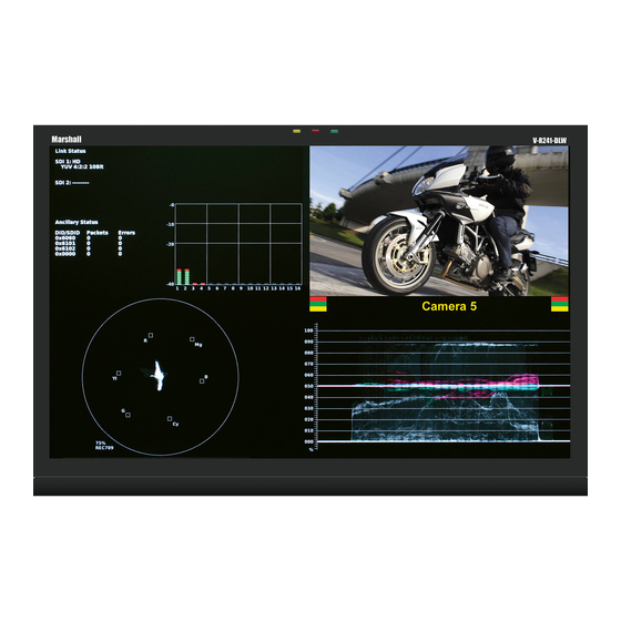
DLW Monitor Layouts The V-R241-DLW has 4 possible layouts, Multi mode, Vectorscope mode, Waveform mode and Full Screen Video mode. Each press of the LAYOUT Button will change the current mode to next available mode. Default Multi mode Layout Vectorscope Mode... - Page 10 Waveform Monitor Mode Full Screen Video Mode...
-
Page 11: On-Screen Menu
On-Screen Menu STRUCTURE OVERVIEW... -
Page 12: Main Menu And Navigation
On-Screen Menu (continued) MAIN MENU AND NAVIGATION Access and navigate the main menu using the RotoMenu™ knob: Main Menu Using the RotoMenu knob • Press the RotoMenu™ knob to enter the main menu. • Rotate the knob to scroll up or down in the main menu or each submenu. •... -
Page 13: 16:9 Markers
■ 16:9 Markers Use this setting to superimpose one of 10 markers on the screen when in 16:9 or Full Screen mode. This setting is disabled when the aspect ratio is set to 4:3, or when Pixel-to-Pixel mode is enabled. Note that in Full Screen mode, markers are vertically stretched along with the picture to fit the 16:10 screen. -
Page 14: Marker Background
4:3 Marker Examples: OFF (No Marker) 90% Safe Area ■ Marker Background Use this setting to choose how selected markers are displayed on the screen: • Off The marker is superimposed on the complete image. • 50% Gray Screen area beyond the marker is shown at 50% intensity. •... -
Page 15: Video Config Submenu
Video Config Submenu Use the Video Configuration submenu to select various video settings such as monochrome mode or blue-only mode. Video Configuration Submenu ■ Monochrome Mode Use this setting to enable monochrome mode. Only the luminance of the image will be displayed as a grayscale picture. -
Page 16: Pixel-To-Pixel Mode
■ Pixel-to-Pixel Mode Use this setting to enable Pixel-to-Pixel mode. This mode bypasses the monitor’s internal scaling function and displays images in their native resolution and aspect ratio, with a one-to-one mapping of incoming image pixels to screen pixels: • For incoming formats smaller than the native resolution of the window (or selected aspect ratio), the image will be displayed in the center of the window using only the necessary LCD pixels. -
Page 17: Curtain Color
■ Curtain Color Use this setting to choose the default color displayed on the screen when no video input is present. Available colors are blue, red, green, white, and black. ■ Ctemp/Gamma Use this setting to choose one of three color temperature / gamma presets or to remove gamma settings: •... -
Page 18: Hdmi Csc Auto
■ HDMI CSC Auto (HDMI input only, via the DVI-I interface) The HDMI CSC Auto setting is used to accommodate newer HDMI interfaces that send colorspace signaling in the HDMI data stream. If this setting is set to On, the monitor will automatically determine which colorspace setting to use. If this setting is set to Off, or your HDMI signal does not contain colorspace signaling, the DVI-D CSC Mode described above will determine the colorspace configuration. -
Page 19: User-Definable Function Buttons
■ User-Definable Function Buttons Use the Function 1, Function 2, Function 3 and Function 4 menu items to define each function button on the front panel of the monitor. The following options are available for each button: • Marker Toggle between different Screen Markers •... -
Page 20: Osd Configuration Submenu
OSD Config Submenu Use the OSD Configuration submenu to select a variety of information to be displayed on the screen. OSD Configuration Submenu ■ IMD State Use this setting to turn the IMD text display on or off. This setting affects both fixed string IMD text and remote IMD text commands. -
Page 21: Osd Tally
■ OSD Tally Use this setting to choose how tally is displayed on the screen. The available OSD Tally options depend on the Tally Source selected in the IMD Configuration submenu When the Tally Source is set to Standard (contact closure), OSD Tally can be set to Off, RGY, RG, or GR: •... -
Page 22: Audio Monitor
Use this setting to enable time code display on the screen. Time code is de-embedded from the vertical ancillary data (VANC) within the HD/SDI signal. Two types of time code can be selected to display on the screen: LTC (linear time code) or VITC (vertical interval time code). -
Page 23: Imd Configuration Submenu
All menu features of the V-R241-DLW can also be controlled via the Marshall Network Controller box using MEI protocol. (Contact Marshall Electronics for additional information). Use the IMD Configuration submenu to configure various IMD parameters as described below. -
Page 24: Tally Source
TSL v4.0 Use the TSL v4.0 protocol setting when controlling the IMD from a TSL tally controller, or other controlling device which utilizes the TSL v4.0 protocol. The IMD # must be set for each screen in conjunction with the controlling device. -
Page 25: Imd Baud Rate
■ IMD Baud Rate Use this setting to choose the baud rate. The baud rate must be set in conjunction with the controlling device. Available baud rates are 300, 600, 1200, 2400, 4800, 9600, 19200, 38400, 57600, 115200. The TSL v4.0 protocol is fixed at 38400 bauds. -
Page 26: Imd Fixed String
■ IMD Fixed String Use this setting to display static IMD text on the screen. This setting is used to enter IMD text locally, when a serial protocol is not used for remote control. The IMD Fixed String is saved after power cycle. The IMD Fixed String will be overridden by serial protocol commands. -
Page 27: Wave/Vector Submenu
The EIA-608 caption protocol can define the color for the closed caption text. Use this setting to choose between using the color defined by the data stream or to override this data with any of the selected colors. The default setting for option is Auto. ■... - Page 28 • RGB Parade The R (shown in Red), G (shown in Green) and B (shown in Blue) components of the signal are displayed from left to right. • RGB Overlay The RGB components of the signal are overlaid. ■ Waveform Scale Use the Waveform scale option to switch between different graticule units on the Waveform display.
-
Page 29: Ancillary Submenu
Use the Colorize Waveform option to add or remove color from the Waveform display. When Colorize Waveform is ON, the YUV and RGB data components on the Waveform display will appear in different colors. When Colorize Waveform is OFF, all YUV and RGB data components will appear as white on the Waveform display. ■... -
Page 30: Did/Sdid
■ DID/SDID Use this section to select which packet IDs should be counted on the DLW monitor display. For example, 0x6060 would count the Timecode data packets, 0x6101 would count the EIA-708 CC data packets and 0x6102 would count the EIA-608 CC data packets. Any ancillary packet ID can be chosen, from 0000 to FFFF. -
Page 31: Service Submenu
SERVICE SUBMENU ■ Software Version Display The Main Board, Keypad, and FPGA software version numbers are displayed. Service Menu The following information is displayed: • rel: Release Package version number • ipa Input processor firmware • dlw FPGA Version • ipap Product Type •... -
Page 32: Specifications
Specifications ■ PANEL ■ TALLY HARDWARE INTERFACE (HD-15) Screen Size 24.1” Diagonal Activation requires contact closure of pin to ground on the HD- Display Area (h x v) 518.4 mm x 324.0 mm 15 connector: Aspect Ratio 16:10 Native Pin No. Signal Pixels 1920 x RGB x 1200... - Page 33 Dimensions...
-
Page 34: Maintenance
This warranty is extended to the first consumer only, and proof of purchase is necessary to honor the warranty. If there is no proof of purchase provided with a warranty claim, Marshall Electronics reserves the right not to honor the warranty set forth above. - Page 35 This page intentionally left blank...
- Page 36 Marshall Electronics, Inc. 1910 East Maple Ave. El Segundo, CA 90245 Tel: (800) 800-6608 / (310) 333-0606 • Fax: 310-333-0688 www.LCDRacks.com • sales@lcdracks.com 2010-1229...
Need help?
Do you have a question about the V-R241-DLW and is the answer not in the manual?
Questions and answers