Table of Contents
Advertisement
Quick Links
SERIAL #:
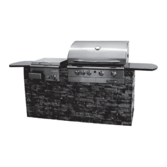
Entertainment Island 6000 SI Barbecue
H E A V Y A R T I C L E N E E D S 2 T O L I F T
5 Y E A R L I M I T E D W A R R A N T Y
8 5 - 1 6 2 0 - 6 P R O P A N E ( G 6 1 5 0 1 )
Read and save this manual for future reference.
If pre-assembled, leave this manual with
unit for consumer's future reference.
Centro Customer Care Hotline
1-877-707-5463
S A F E U S E , C A R E A N D A S S E M B L Y M A N U A L
D A N G E R
If You Smell Gas
1. Shut off gas to the appliance.
2. Extinguish any open flame.
3. Open lid.
4. If odor continues, keep away from the
appliance and immediately call your
gas supplier or your fire department.
W A R N I N G
1. Do not store or use gasoline or other
flammable liquids or vapors in the
vicinity of this or any other appliance.
2. An LP cylinder not connected for use
shall not be stored in the vicinity of
this or any other appliance.
W A R N I N G
Failure to follow all of the manufacturer's
instructions could result in hazardous
fires, explosions, property damage,
or serious personal injury or even death.
W A R N I N G
Follow all leak check procedures carefully
prior to operation of barbecue,
even if barbecue was store assembled.
Do not try to light this barbecue
without reading the Lighting Instructions
section of this manual.
T H I S B A R B E C U E I S F O R
O U T D O O R U S E O N L Y
Before assembling please note:
Natural gas conversion kit is available
at Canadian Tire #85-1621-4
Advertisement
Table of Contents

Subscribe to Our Youtube Channel
Related Manuals for Centro Entertainment Island 6000 SI Barbecue


Summary of Contents for Centro Entertainment Island 6000 SI Barbecue
- Page 1 T H I S B A R B E C U E I S F O R Centro Customer Care Hotline O U T D O O R U S E O N L Y...
-
Page 2: Table Of Contents
Warranty ....ii This Centro BBQ carries a five year limited warranty against defects in manufacturing work- Installation Information ..1 manship. -
Page 3: Installation Information
I N S T A L L A T I O N The installation of this appliance must be in accordance with all local codes, or in the absence of local codes: I N F O R M A T I O N Canadian installation must conform to the current national standards, which at this time •... -
Page 4: Transportation And
The Cylinder must also be equipped with: D A N G E R A shut-off valve with a correct cylinder valve outlet as specified in current standards. • NEVER store a spare LP tank under • Canada: CAN / CGA 1.6g-M97 Outdoor Gas Grilles. •... -
Page 5: Prior To Using The Grill
P R I O R T O U S I N G Do not use your barbecue until you have carefully read and fully understand all the information in this manual. Please ensure the following: Your barbecue is properly assembled. •... -
Page 6: Safety Hose And Regulator
S A F E T Y H O S E Propane Gas Models: Your barbecue is designed to operate on L.P. (Propane) gas at a pressure of 2.74 Kpa (11˝ water column). A regulator preset to this pressure is supplied with A N D R E G U L A T O R the barbecue and must be used. -
Page 7: Safety Leak Testing
To Reset The Gas Regulator Safety Device 1. Close the LP (propane) tank valve. 2. Turn all burner control knobs to the OFF position. 3. Disconnect the regulator from the LP tank. 4. Open the grill lid. 5. Open all of the control knobs to the high position. 6. -
Page 8: Lighting The Grill
L I G H T I N G Make Sure you have followed all the safety checks, procedures and instructions indicated in the previous section, before attempting to light the grill. T H E G R I L L Lighting The Main Burners 1. - Page 9 6. Confirm that the burner is properly lit. If the flame pattern is other than normal, consult the Troubleshooting Guide for corrective action. 7. Always preheat the Barbecue before starting to cook. Light all burners and adjust them to the HIGH position for 5-10 minutes. Before placing any food on the Barbecue, clean the cooking grids with a Porcelain cleaning brush.
- Page 10 Lighting the Side Burner Use the Electronic Igniter on the main control panel and the Side Burner control knob, on the far left panel, to light the side burner. Push in and turn the side burner control knob to the HIGH position. •...
-
Page 11: Sear Zone
When the BBQ is not in use, always cover the infrared burner with the Storage cover provided, to avoid burner damage caused by moisture or harsh weather. Purchase a Centro BBQ Cover to help protect your grill. Operating the infrared burner 1. -
Page 12: Rotisserie Burner
R O T I S S E R I E B U R N E R Turn all knobs to “OFF” • Open lid during lighting. Turn gas on at LP tank. • O P E R A T I N G I N S T R U C T I O N S Push in and turn the Rotisserie Burner Knob to the “ON”... - Page 14 P A R T S L I S T I N G F O R C E N T R O 6 0 0 0 S I B B Q A N D M U L T I - P U R P O S E S I D E B U R N E R 8 5 - 1 6 2 0 - 6 P R O P A N E ( G 6 1 5 0 1 ) Item No.
- Page 15 E N T E R T A I N M E N T I S L A N D C E N T R O 6 0 0 0 S I B A R B E C U E 8 5 - 1 6 2 0 - 6 P R O P A N E ( G 6 1 5 0 1 )
- Page 16 E N T E R T A I N M E N T I S L A N D M U L T I P U R P O S E S I D E B U R N E R 8 5 - 1 6 2 0 - 6 P R O P A N E ( G 6 1 5 0 1 ) Manual Hardware...
- Page 17 C E N T O 6 0 0 0 S I B B Q A N D M U L T I - P U R P O S E S I D E B U R N E R A S S E M B L Y I N S T R U C T I O N S Hardware Pack List Description...
- Page 18 P A R T S L I S T I N G F O R Item No. Quantity Specification Part No. Top Rear Granite Support Brace G615-0061-01 E N T E R T A I N M E N T Rear Island Wall G615-0055-01 I S L A N D A N D G R A N I T E...
- Page 19 E N T E R T A I N M E N T I S L A N D W I T H G R A N I T E C O U N T E R T O P 8 5 - 1 6 2 0 - 6 ( P R O P A N E ) ( G 6 1 5 0 1 ) Hardware Pack...
-
Page 20: Assembly Instructions
E N T E R T A I N M E N T I S L A N D A N D G R A N I T E C O U N T E R T O P A S S E M B L Y I N S T R U C T I O N S Hardware Pack List Description Quantity... - Page 21 Note: Hardware for Steps #1-21 are provided in Fig. 1 the Entertainment Island with Granite Countertop hardware pack. Assemble the Bottom Support feet (EK) (x4) and Nut (x4) to the Bottom Panel (EL) as shown. Tighten all bolts. Turn Bottom Panel over. Fig.
- Page 22 Fig. 4 Align and connect the Left (ET) and Right (EI) Island Walls to the Top Support Bar (Ed) using Hardware C, D, and E as shown. Fig. 5 Align and connect the Front Island Wall (EM) to the Left and Right Island Walls (ET + EI) using Hardware B, C, D, E as shown.
- Page 23 Fig. 7 Assemble the Bottom Panel (EL) by using Hardware F, G, and H. Fig. 8 Once the Bottom Panel (EL) has been attached to the Front and Rear Island Walls (EM + EB), you can now attach the Bottom Panel (EL) to the Left and Right Island Wall (ET + EI) using Hardware C, D, and E.
- Page 24 Fig. 10 Connect the BBQ and Side Burner support bars (EF) to the rear island wall (EB) using hardware D, E and B. Fig. 11 Connect the front BBQ and side burner support bars (EF) to the front Island wall (EM) using hardware D, E and C. Fig.
- Page 25 Fig. 13 Insert and Attach the Top rear granite support brace (EA) to the Rear Island Wall (EB) using hardware C, D and E. Fig. 14 Insert and attach the Top Front Granite Support brace (ES) to the Front Island Wall (EM), together with the Support Bracket, as shown using hardware F, G and H.
- Page 26 Fig. 16 Mount the Left granite Side Shelf (EE) to the Left Island Wall (ET) using the Shelf Support Bracket (EJ) and hardware C, D, E, F, G and H, as shown. Fig. 17 Attach the Trash Basket (EQ) to the Left Door (EP) using hardware D, E and C.
- Page 27 Fig. 19 Assemble the right door (EN) to the Front Island Wall (EM) by slid- ing the door into the hinges from the top as shown. No hardware is needed in this step. Turn Fig. 20 Assemble the Left Door (EP) to the lower hinges by sliding the door into the hinges from left to right, as shown.
- Page 28 Hardware for Steps 22-24 are provided in Centro 6000 SI Fig. 22 BBQ and Multi-purpose Side Burner hardware pack. Assemble the 2 tracks of Pull-out Tank Tray (DK) to the bottom panel (located inside the right door) by using 1/4”-20UNC x 13 screw (x6), 7mm flat washer (x6), and 7mm lock washer (x6), as shown.
- Page 29 Fig. 25 Connect the female and male ends of the QDD device found under the main grill head and Side Burner. Follow by connecting the Hose and Regulator to the Propane tank. Make sure the hose and regulator will pass through the front gap between the front panels and grill body.
- Page 30 Fig. 26 Open lid and position the 3 Flame Tamers (BL) above the 3 Main Burners (BI&BJ). Place the 2 cooking grate (BN) into the burner box to the left as shown. Place the “SEARZONE” cooking grate (BO) above the Sear Zone (BK). Remember to cover the Sear Zone Burner with cover (BM) when not in use to avoid burner damage caused by damp conditions, rain or snow.
- Page 31 Fig. 29 Place the Side Burner Grate (DD) or Griddle (DC) onto the Side Burner for different cooking purpose.
- Page 32 D I S T R I B U T O R Trileaf Distribution Trifeuil Toronto, Canada M4S 2B8...
Need help?
Do you have a question about the Entertainment Island 6000 SI Barbecue and is the answer not in the manual?
Questions and answers