
Related Manuals for Campbell ET106


Summary of Contents for Campbell ET106
- Page 1 ET106 Weather Station Revision: 9/02 C o p y r i g h t ( c ) 1 9 9 3 - 2 0 0 2 C a m p b e l l S c i e n t i f i c , I n c .
- Page 2 Warranty and Assistance The ET106 WEATHER STATION is warranted by CAMPBELL SCIENTIFIC, INC. to be free from defects in materials and workmanship under normal use and service for twelve (12) months from date of shipment unless specified otherwise. Batteries have no warranty. CAMPBELL SCIENTIFIC, INC.'s obligation under this warranty is limited to repairing or replacing (at CAMPBELL SCIENTIFIC, INC.'s option) defective products.
-
Page 3: Table Of Contents
ET 106 Weather Station Table of Contents PDF viewers note: These page numbers refer to the printed version of this document. Use the Adobe Acrobat® bookmarks tab for links to specific sections. 1. Preparation and Siting..........1-1 1.1 Installation Tasks .................. 1-1 1.2 Tools Required.................. - Page 4 This is a blank page.
-
Page 5: Preparation And Siting
Section 1. Preparation and Siting These guidelines apply to several different Campbell Scientific weather stations. 1.1 Installation Tasks 1.1.1 Indoors Immediately upon receipt of your shipment… ⇒ Open shipping cartons. ⇒ Check contents against invoice. Contact CSI immediately about any shortages. -
Page 6: Tools Required
Section 1. Preparation and Siting UT30 (10 meter tower) tower stations: ⇒ Install 3 to 10 meter level sensors (Section 4) ⇒ Raise tower (Section 2) ⇒ Install instrumentation enclosure (Section 3) ⇒ Install 0 to 3 meter level sensors (Section 4) ET101 / ET106 ET Stations: ⇒... -
Page 7: Tools For Instrumentation And Maintenance
Section 1. Preparation and Siting ET Tower Tape measure (12’ to 20’) Claw hammer Level (24” to 36”) Hand saw Materials for concrete form: (4) 1" x 2" x 12" stakes (2) 2" x 4" x 96" lumber (12) 8p double-head nails (8) 16p double-head nails 20 ft form wire ½... -
Page 8: Supplies For Power And Communications Options
Section 1. Preparation and Siting Step ladder (6') Datalogger prompt sheet (Section 6) Station manuals Station log and pen Open end wrenches: 3/8", 7/16", ½", (2) 9/16" Socket wrench and 7/16" deep well socket Adjustable wrench Pliers Conduit and associated tools (as required) Felt-tipped marking pen Claw hammer Pipe wrench (12") -
Page 9: Siting And Exposure
Section 1. Preparation and Siting 1.3 Siting and Exposure If any part of the weather station comes in contact with CAUTION power lines, you could be killed. Contact local utilities for the location of buried utility lines before digging or driving ground rods. -
Page 10: Solar Radiation
Section 1. Preparation and Siting Standard measurement heights: 1.5 m ± 1.0 m (AASC) 1.25 - 2.0 m (WMO) 2.0 m temperature (EPA) 2.0 m and 10.0 m for temperature difference (EPA) 1.3.3 Precipitation A rain gage should be sited on level ground that is covered with short grass or gravel. -
Page 11: Determining True North For Wind Vane Orientation
Section 1. Preparation and Siting REGCOMENDED Feed SENSORS Portland Or USA Serial 27115 REGCOMENDED Feed SENSORS Serial 27115 27115 Portland Or USA i a l FIGURE 1.3-1. Effect of Structure on Wind Flow 1.4 Determining True North for Wind Vane Orientation Magnetic declination, or other methods to find True North, should be determined prior to installing the weather station. -
Page 12: Nssdc Cgm Service
Section 1. Preparation and Siting Subtract declination from 360 Add declination to 0 20 W 22 E 18 W 16 W 20 E 14 W 12 W 18 E 10 W 16 E 14 E 12 E 10 E FIGURE 1.4-1. Magnetic Declination for the Contiguous United States 1.4.1 NSSDC CGM Service The NSSDC CGM (Corrected Geomagnetic) Service provides an easy way of determining magnetic declination of a specific site. - Page 13 Section 1. Preparation and Siting Geographic Alt. IGRF Magnetic Field Dipole Lat. Long. (km) Lat. Long. H(nT) D(deg) Z(nt) Lat. Long. 42.03 248.15 49.80 311.06 20608. 14.417 50505. 49.68 312.14 Magnetic declination is bold in this example to show its location in the table. A positive declination is east, while a negative declination is west.
- Page 14 Section 1. Preparation and Siting References EPA, (1987). On-Site Meteorological Program Guidance for Regulatory Modeling Applications, EPA-450/4-87-013. Office of Air Quality Planning and Standards, Research Triangle Park, North Carolina 27711. WMO, (1983). Guide to Meteorological Instruments and Methods of Observation. World Meteorological Organization No. 8, 5th edition, Geneva, Switzerland.
-
Page 15: Et Tower Installation
Section 2. ET Tower Installation DANGER: Do not install near power lines. If any part of the tower comes in contact with power lines you could be KILLED. Contact local utilities for the location of buried utility lines before digging or driving grounding rods. CAUTION: Do not fit the 3 meter ET Tower sections together until the appropriate time. - Page 16 Section 2. ET Tower Installation 2.1.2 Installation The ET Tower attaches to a user supplied concrete foundation constructed as shown in Figure 2.1-2. Construct the concrete form with 2" x 4" lumber and 16p nails. Assemble the template and anchor bolts. There should be two nuts below and one nut above the template on each bolt.
-
Page 17: Tower Installation
Section 2. ET Tower Installation SIDE VIEW FORM TOP VIEW 2" FORM WIRE NORTH ANCHOR BOLT 24" 24" SMALL CAVITY CEMENT PAD 24" FORM WIRE TEMPLATE FIGURE 2.1-2. ET Tower Base Installation 2.2 Tower Installation 2.2.1 Supplied Components (1) Upper Tower Section (Tapered) (1) Lower Tower Section (6) ½... -
Page 18: Tower Grounding
Section 2. ET Tower Installation Cut and save a 9 inch piece of 12 AWG ground wire from the 12 foot length provided. Thread the remaining 11 foot ground wire through the tower. Secure all wiring so it does not slip back into the tower or conduit. Place the tower cap over the tower end. -
Page 19: Grounding Procedure
Section 2. ET Tower Installation 2.3.2 Grounding Procedure Ground the tower as shown in Figure 2.2-1. Place the ground rod clamp on the rod. Secure it about 3 inches from the top. Do this before the rod is driven into the ground. Be careful not to damage the clamp with the hammer Taking care not to damage power or communications lines, drive the ground rod close to the foundation using a fence post driver or sledge... - Page 20 Section 2. ET Tower Installation This is a blank page.
-
Page 21: Et Instrumentation Installation
Section 3. ET Instrumentation Installation The weather station datalogger, power supply, sensor connection panel, communications devices, and data retrieval peripherals are mounted in the ET enclosure at the locations shown in Figure 3-1. Components include: (1) ET Enclosure (1) 4 unit Desiccant Pack (1) Flat Point Screw Driver (1) Power Supply Option (1) Telecommunications Option... -
Page 22: Enclosure, Datalogger, Power Supply
Section 3. ET Instrumentation Installation 3.1 Enclosure, Datalogger, Power Supply 3.1.1 Battery Option Installation a) Alkaline Option: The BPALK houses 8 "D" cell batteries. Install it as shown in Figure 3.1-1. Remove the external circuit board with wire and connector by loosening the 2 Phillips head screws. Discard the external circuit board. -
Page 23: Solar Panel Installation
Section 3. ET Instrumentation Installation 3.1.2 Solar Panel Installation FIGURE 3.1-3. Solar Panel Mounting a) Mount the solar panel to the tower using the mounting brackets as shown in Figure 3.1-3. Mount the solar panel to the tower so it faces south (northern hemisphere). - Page 24 Section 3. ET Instrumentation Installation b) Shut off 110 VAC power at the main breaker. Connect the primary leads of the transformer to 110 VAC following instructions provided with the transformer. Connect a two-conductor cable to the secondary terminals of the transformer.
-
Page 25: Sensor Connection
Section 3. ET Instrumentation Installation e) Strip 1 inch of insulation from each end of the 9-inch piece of 12 AWG ground wire. Insert one end into the brass ground lug located at the top back of the enclosure. Curl the other end and place under the head of one of the lightning rod clamp bolts. -
Page 26: Communication And Data Storage Peripherals
Section 3. ET Instrumentation Installation 604 Ohm (LI190SB) Open (LI1200X) 100 Ohm (LI200S) (HMP35C) Open (CS500, HMP45C) Open SW 12V (CS500, HMP45C) Open (HMP35C) FIGURE 3.2-2. Default Sensor Switch Settings 3.3 Communication and Data Storage Peripherals One communications kit can be mounted to the ET Enclosure back plate. Communications kits ordered with the ET Enclosure are pre-mounted and pre- wired;... -
Page 27: Internal Installation
Section 3. ET Instrumentation Installation 3.3.1.1 Internal Installation For installation inside the ET Enclosure, the following components are provided in the phone modem kit: (1) COM200 or COM300 Phone Modem (1) 12 inch RJ-11 Patch Cord (1) Mounting Bracket (4) Screws (1) 12 inch 14 AWG Ground Wire Install the phone modem as shown in Figure 3.3-1. - Page 28 Section 3. ET Instrumentation Installation 3.3.2.1 Internal Installation For installation inside the ET Enclosure, the following components are provided in the cell phone modem kit: (1) COM100 Transceiver, Power Connector (1) Mounting Bracket (6) Screws (1) 12 inch Coaxial Patch Cable Install the phone modem and cellular transceiver as shown in Figure 3.3-2.
- Page 29 Section 3. ET Instrumentation Installation Motorola M600 Transceiver COM200 or VS1 Telephone Modem Green Modem Ground Wire to Modem “GND” Terminal Green Modem Ground Wire to Recessed “GND” Lug Cellular Power Connector Blue 9 Pin Ribbon Cable RJ11C (1 Extra Connector) Patch Cord Cellular Handset Connector...
- Page 30 Section 3. ET Instrumentation Installation 3.3.2.2 External Installation The following cellular kit components are used to make the external connections: (1) Cellular Antenna (1) 9 foot Coaxial Antenna Cable (1) Antenna Mounting Bracket FIGURE 3.3-3. Cellular Phone Antenna Mounting 1) Mount the antenna to the ET Tower as shown in Figure 3.3-3. 2) Connect the antenna to the external coaxial bulkhead connector with the 9-foot antenna cable.
- Page 31 Section 3. ET Instrumentation Installation 3.3.3.1 Internal Installation For installation inside the ET Enclosure, the following components are provided in the short-haul modem kit: (1) SC932C Interface (1) Rad Modem (1) Rad/SC932C Mounting Bracket (4) Screws (1) 12 inch 4-wire patch cable Install the short-haul modems as shown in Figure 3.3-4 and 3.3-5.
-
Page 32: Sealing And Desiccating The Enclosure
Section 3. ET Instrumentation Installation 3) Connect the 5-foot patch cord to the Rad Modem. Fasten the cable to the strain relief tab with a cable tie. Connect the Rad to the PC's serial port either directly (25 pin port) or through a 9 to 25 pin serial converter. 4) Route the user-supplied cable from the remote splice to the surge protector. - Page 33 Section 3. ET Instrumentation Installation Desiccant Pack FIGURE 3.4-1. Desiccant Installation 3-13...
- Page 34 Section 3. ET Instrumentation Installation This is a blank page. 3-14...
-
Page 35: Et106 Sensor Arm Installation
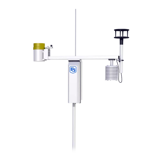
Section 4. ET106 Sensor Arm Installation 4.1 Components (1) ET106 Sensor Arm (1) Met One 034A Wind Sensor (1) 034A Mounting Shaft (1) Radiation Shield 4.2 Installation Install the ET106 Sensor Arm after the ET Enclosure is mounted low on the ET Tower. -
Page 36: 034A Wind Sensor Installation
Section 4. ET106 Sensor Arm Installation 4.4 034A Wind Sensor Installation Install the 034A Wind Sensor as shown in Figure 4.4-1 after the sensor arm is securely installed. The wind vane is oriented after the datalogger has been programmed (Section 5), and the location of True North has been determined (Section 1.2). -
Page 37: Rh And Temperature Radiation Shield
Section 4. ET106 Sensor Arm Installation 4.5 RH and Temperature Radiation Shield Mount the radiation shield to the sensor arm as shown in Figure 4.4-1. Place the RH and temperature assembly inside the shield shaft. Attach the shield to the sensor arm with the two screws. 4.6 Pyranometer Level the pyranometer as indicated in Figure 4.6-1. -
Page 38: Upgrading An Et101 To An Et106
Section 4. ET106 Sensor Arm Installation Input Normal Location Parameter Range Battery (Volt) 9.6 to 14.0 Volts Enclosure Temperature (°C) Close to air temperature Air Temperature (°C) -40° to +50° Air Temperature (°F) -40° to +122° RH (%) 0 to 100% Solar Radiation(kW m 0 to 1.2 kW m Wind Speed (mph) - Page 39 Section 4. ET106 Sensor Arm Installation ET101 to ET106 Logan, Utah MADE IN USA FIGURE 4.9-1. Upgrading the ET101 to an ET106 FIGURE 4.9-2. Modifying the Pyranometer Plate...
-
Page 40: Sensor Schematics
Section 4. ET106 Sensor Arm Installation Metal Washers FIGURE 4.9-3. Installing Leveling Screws 4.10 Sensor Schematics Schematics of ET106 sensors and associated connectors are provided in Figures 4.10-1, 4.10-2, 4.10-3, and 4.10-4 for help in troubleshooting. Knowledge of the schematics is not necessary for routine installation and maintenance. - Page 41 Section 4. ET106 Sensor Arm Installation Wind Speed and Wind Direction Connector Datalogger 10K OHM Excitation Wind Direction 1K OHM Signal Return 10K OHM Potentiometer Analog Ground Pulse Wind Speed Magnetically Activated Reed Switch Ground Shield FIGURE 4.10-2. Schematic of 034A-LC Wind Speed and Direction Probe and Connector #2 Connector Datalogger Solar Radiation...
- Page 42 Section 4. ET106 Sensor Arm Installation Connector Tipping Rain Bucket Not Used Not Used Not Used Datalogger Pulse Magnetically Activated Reed Switch Ground Shield FIGURE 4.10-4. Schematic of TE525-LC Rain Sensor and Connector #5...
-
Page 43: Et Software Installation
Section 5. ET Software Installation The ET Evapotranspiration Stations are supported by PC120 "ETPro" for MS-DOS. ETPro is used to write and download the station program, and to retrieve and report data. ETPro works in conjunction with PC208 Datalogger Support Software. PC120 and PC208 each have their own manual, which should be consulted for installation procedures and operational details. - Page 44 Section 5. ET Software Installation This is a blank page.
-
Page 45: Maintenance And Troubleshooting
Section 6. Maintenance and Troubleshooting These guidelines apply to several different Campbell Scientific weather stations. 6.1 Maintenance Proper maintenance of weather station components is essential to obtain accurate data. Equipment must be in good operating condition, which requires a program of regular inspection and maintenance. Routine and simple maintenance can be accomplished by the person in charge of the weather station. -
Page 46: Sensor Maintenance
Section 6. Maintenance and Troubleshooting 6.1.3 Desiccant Enclosure humidity is monitored in the ET Enclosure and MetData1 systems by an RH chip incorporated into the connector board. Change the desiccant packs when the enclosure RH exceeds 35%. The RH chip should be changed every 3 to 5 years. -
Page 47: Troubleshooting
Section 6. Maintenance and Troubleshooting 1 year Replace anemometer bearings. Calibrate the rain gage. Calibrate the HMP45C/HMP35C probe. Check calibration of CS500 RH Probe; replace RH chip if necessary. Check internal RH chip (MetData1 and ET101/106 only). Replace if >5% off. -
Page 48: Displayed In An Input Location
Section 6. Maintenance and Troubleshooting C. Make sure the datalogger is connected to the modem, and the modem is properly configured and cabled (Section 9). At the computer: D. Make sure the Station File is configured correctly (PC208 Manual). E. Check the cable(s) between the serial port and the modem. If cables have not been purchased through Campbell Scientific, check for the following configuration using an ohm meter: 25-pin serial port:... - Page 49 Section 6. Maintenance and Troubleshooting 6.2.5 6999 or 99999 Stored in Final Storage (or Storage Module) A. Final Storage format limitations exceeded (any number larger than 6999 in low resolution, or 99999 in high-resolution format is stored as the maximum number). Change the datalogger program.
- Page 50 Section 6. Maintenance and Troubleshooting This is a blank page.
- Page 51 This is a blank page.
- Page 52 Campbell Scientific Companies Campbell Scientific, Inc. (CSI) 815 West 1800 North Logan, Utah 84321 UNITED STATES www.campbellsci.com info@campbellsci.com Campbell Scientific Africa Pty. Ltd. (CSAf) PO Box 2450 Somerset West 7129 SOUTH AFRICA www.csafrica.co.za sales@csafrica.co.za Campbell Scientific Australia Pty. Ltd. (CSA) PO Box 444 Thuringowa Central QLD 4812 AUSTRALIA...
Need help?
Do you have a question about the ET106 and is the answer not in the manual?
Questions and answers