Table of Contents
Advertisement
Quick Links
Download this manual
See also:
Instruction Manual
Advertisement
Table of Contents
Troubleshooting

Related Manuals for Campbell ET107


Summary of Contents for Campbell ET107
- Page 1 Product Manual Revision: 08/2019 Copyright © 1993 – 2019 Campbell Scientific...
- Page 3 Quotations for repairs can be given on request. It is the policy of Campbell Scientific to protect the health of its employees and provide a safe working environment, in support of this policy a “Declaration of Hazardous Material and Decontamination”...
- Page 5 PLEASE READ FIRST About this manual Please note that this manual was originally produced by Campbell Scientific Inc. primarily for the North American market. Some spellings, weights and measures may reflect this origin. Some useful conversion factors: Area: 1 in...
- Page 7 • Periodically (at least yearly) check electrical ground connections. WHILE EVERY ATTEMPT IS MADE TO EMBODY THE HIGHEST DEGREE OF SAFETY IN ALL CAMPBELL SCIENTIFIC PRODUCTS, THE CUSTOMER ASSUMES ALL RISK FROM ANY INJURY RESULTING FROM IMPROPER INSTALLATION, USE, OR MAINTENANCE OF TRIPODS, TOWERS, OR ATTACHMENTS TO TRIPODS AND TOWERS...
-
Page 9: Table Of Contents
Table of contents 1. Introduction 2. Precautions 3. Initial inspection 4. QuickStart 4.1 User-supplied tools 4.2 Supplies for power and communications options 5. Siting and exposure 5.1 Wind speed and direction 5.2 Temperature and relative humidity 5.3 Solar radiation 5.4 Soil temperature 6. - Page 10 6.6.10 Sensor verification and clock set 6.7 Communication peripherals 6.7.1 Direct connect to ET107 station 6.7.2 Phone modem 6.7.2.1 Internal installation of phone modem 6.7.2.2 External installation of phone modem 6.7.3 Short-haul modem 6.7.3.1 Internal installation of short haul modem 6.7.3.2 External installation of short haul modem...
- Page 11 8.3 Communication modems schematics 9. References Appendix A. Wind direction sensor orientation A.1 Determining True North and Sensor Orientation Appendix B. ET107 maintenance log Appendix C. PS24 24 Ah power supply with 10 x 12 inch enclosure C.1 PS24 components C.2 PS24 installation Appendix D.
-
Page 13: Introduction
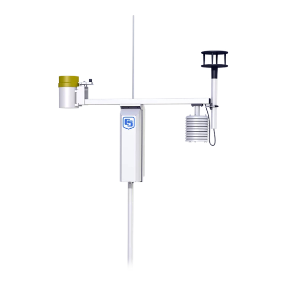
1. Introduction The ET107 is an automated weather station designed for irrigation scheduling in turf grass and commercial agriculture applications. A properly programmed station calculates potential evapotranspiration (ETo), which is the amount of water lost from the soil due to evaporation and plant transpiration. -
Page 14: Precautions
Save the caps for shipping or storing the sensors. Campbell Scientific recommends routing the cable of the optional soil sensors in conduit, especially if the soil is rocky or rodents are present. The cables for these sensors do NOT have an armored outer jacket. -
Page 15: Initial Inspection
3. Initial inspection Immediately upon receipt of your shipment: 1. Open shipping carton(s). Solar panel and radio frequency (RF) items (if any) will be packed in a separate box. 2. Set the large weather station carton down lengthwise on a floor or table top. 3. - Page 16 8. Securely tape box shut if transporting entire station to another site. 9. If at the main site, remove communication components that are installed at the calling computer. Repackage remaining components for transport to field site. FIGURE 3-3. ET107 with the Met One 034B-ETM Wind Sensor, top layer Section 3. Initial inspection...
- Page 17 FIGURE 3-4. ET107, bottom layer Section 3. Initial inspection...
-
Page 18: Quickstart
(p. 12)) 3. Install the ET107 pole (Pole installation (p. 16)). 4. Place instrumentation enclosure on the ET107 pole, slide the enclosure to the top of the pole, and secure it with the correct orientation (Enclosure installation (p. 19)). 5. Install the crossarm and sensors (Crossarm installation procedure (p. - Page 19 (4) 2.5 cm x 5 cm x 30 cm (1 in x 2 in x 12 in) stakes (2) 5 cm x 10 cm x 240 cm (2 in x 4 in x 96 in) lumber (12) 8p double-head nails (8) 16p double-head nails 6 m (20 ft) form wire 0.5 m (0.5 yard) concrete...
-
Page 20: Supplies For Power And Communications Options
AC Power Wire, conduit, and junction boxes as needed (FIGURE 4-1 (p. 8)). FIGURE 4-1. ET107 pole installation with currently-available AC power option NOTE: User supplies valve box at base of station and weatherproof enclosure for transformer (FIGURE 4-1 (p. 8)). - Page 21 677-2600)) or equivalent type cable (FIGURE 4-1 (p. 8)). Radio Antenna for the ET107 station (Yagi antenna recommended). PS24 Power Supply and mounting kit with hangar if not using AC power (PS24 24 Ah power supply with 10 x 12 inch enclosure 91)).
-
Page 22: Siting And Exposure
5. Siting and exposure DANGER: If any part of the weather station comes in contact with power lines, you could be killed. Contact local utilities for the location of buried utility lines before digging or driving ground rods. Selecting an appropriate site for the weather station is critical to obtain accurate meteorological data. -
Page 23: Temperature And Relative Humidity
5.2 Temperature and relative humidity Sensors should be located over an open, level area at least 9 m (29.5 ft) (EPA) in diameter. The surface should be covered by short grass, or where grass does not grow, the natural earth surface. Sensors should be located at a distance of at least four times the height of any nearby obstruction and at least 30 m (98.43 ft) (EPA) from large paved areas. -
Page 24: Installation
6.12 Sealing and desiccating the enclosure 6.13 ET107 software 6.1 Base foundation installation The following components included with the ET107 are used for this installation procedure: (3) 16 mm (5/8 in) anchor L-bolts (9) 16 mm (5/8 in) nuts (1) anchor template... - Page 25 FIGURE 6-1. ET107 pole base installation 1. Construct the concrete form with 5 cm x 10 cm (2 in x 4 in) lumber and 16p nails. 2. Assemble the template and anchor bolts. For each bolt, place two nuts below and one nut above the template.
-
Page 26: Ac Power Installation Procedure
threads should be about 1 cm (0.5 in) above the concrete (FIGURE 6-2 (p. 14)). The template must be level in two dimensions. FIGURE 6-2. Cut-away view shows anchor bolt and conduit placement in cement pad 12. Use a trowel and edger to finish. 13. - Page 27 3. Connect the primary leads of the power supply to the 100 to 240 VAC power source. 4. Connect a two-conductor cable to the secondary terminals of the power supply. 5. Route the cable from the power supply to the ET107 enclosure according to local electrical codes.
-
Page 28: Pole Installation
FIGURE 6-3. Position of bulkhead connectors 6.3 Pole installation The following components included with the ET107 are used for this installation procedure: (1) top pole section (tapered) (1) base pole section (6) 5/8-inch washers Section 6. Installation... - Page 29 (1) 6 x 19 mm (1/4 x 3/4 in) hex head self-drilling screw The pole provides a support structure for mounting the ET107 weather station components. The pole is designed to withstand winds of 45 m/s (100 mph). The lightning rod assembly is attached after the instrumentation enclosure is installed.
-
Page 30: Pole Grounding
15. Tighten the three top nuts with the wrench. 6.3.1 Pole grounding The following components included with the ET107 are used for this installation procedure: (1) 4 AWG ground wire (1) 8 AWG ground wire (1) copper ground lug, bolt... -
Page 31: Enclosure Installation
FIGURE 6-5. Close-up of ground rod and 4 AWG cable 6.4 Enclosure installation The weather station data logger, power supply, sensor connection panel, communications devices, and data retrieval peripherals are mounted in the ET107 enclosure. Mount the enclosure on the pole as shown in FIGURE 6-6 (p. -
Page 32: Crossarm Installation Procedure
1. Remove the front lid. 2. Remove the connector cover from the back of the enclosure by loosening the Phillips screw at the bottom of the cover. 3. Loosen the mounting bracket bolts on the back of the enclosure wide enough to slide over the pole. -
Page 33: Sensor Installation
(pyranometer) on the south side for northern latitudes and the reverse for southern latitudes. 6.6 Sensor installation The following components included with the ET107 are used for this installation procedure: (1) ET107 crossarm with sensors (FIGURE 6-8 (p. -
Page 34: Rh And Temperature Radiation Shield Installation Procedure
FIGURE 6-8. ET107 instrumentation mounted on the ET107 pole 6.6.1 RH and temperature radiation shield installation procedure 1. Remove the two knurled thumb screws taped underneath the crossarm. 2. Remove the yellow shipping cap from the end of the temperature/relative humidity sensor (FIGURE 6-9 (p. - Page 35 FIGURE 6-9. Temperature/relative humidity sensor with yellow protective cap FIGURE 6-10. Temperature/relative humidity sensor without yellow protective cap 3. Insert the temperature/relative humidity into the radiation shield until it stops. 4. Attach the radiation shield to the underside of the crossarm using the two knurled thumb screws from step 1.
-
Page 36: Wind Sensor (Wind Sensor Option -Mw)
6.6.2 034B Wind Sensor (wind sensor option -MW) Do the following to install the 034B Wind Sensor after the crossarm is securely installed (FIGURE 6-11 (p. 24)). FIGURE 6-11. Wind and RH/temperature sensor installation Section 6. Installation... - Page 37 FIGURE 6-12. 034B mounting to pipe WARNING: The wind vane can be easily damaged if dropped or bent. Leave the 034B wind vane in the protective cardboard sleeve until it’s ready to be installed. 1. Remove the alignment screw at the base of the 034B-ET (FIGURE 6-12 (p.
-
Page 38: Windsonic 2-D Ultrasonic Wind Sensor (Wind Sensor Option -Gw)
(Changing the jumper (p. 26)). NOTE: Jumper is set at the factory if the WindSonic is ordered with the ET107 station. 6.6.3.1 Changing the jumper The procedure to change the jumper follows: 1. Remove the cover of the enclosure. 2. Disconnect the ribbon cable from the CS I/O port. - Page 39 FIGURE 6-13. Screws that secure the electronics cover 4. Remove the electronics cover to expose the printed circuit board (PCB) (FIGURE 6-14 (p. 27)). FIGURE 6-14. Removal of the electronics cover 5. Move the jumper at the top of the PCB so that it is placed over the centre and right pins (FIGURE 6-15 (p.
-
Page 40: Windsonic Attachment To Crossarm
FIGURE 6-15. Jumper set for WindSonic1 6. Replace electronics cover. 7. Tighten screws. 8. Reattach the ribbon cable to the CS I/O port. 9. Replace enclosure cover. 6.6.3.2 WindSonic attachment to crossarm 1. Remove the three Phillips screws from the end of the white mounting shaft. 2. - Page 41 FIGURE 6-16. WindSonic mounting shaft 4. Slide the connector and cable up through the centre of the mounting shaft. 5. Plug the cable into the sensor. The connector has a key and needs to be pushed in then rotated clockwise to lock it in place (FIGURE 6-17 (p.
-
Page 42: Rain Gauge
FIGURE 6-17. WindSonic connected to cable 6. Centre the WindSonic over the three threaded screw holes on the mounting shaft and screw it in place using the three Phillips screws taken off the shaft in step 1. 7. Slide the shaft and sensor back through the U-bolt. 8. -
Page 43: Pyranometer
1. Pull the gold funnel up and off of the top of the rain gauge. 2. Remove the rubber band holding the tipping mechanism in place (FIGURE 6-18 (p. 31)). FIGURE 6-18. Remove rubber band from tipping mechanism 3. Adjust the bolts at the bottom of the pole as needed to get the bubble level centered. 4. - Page 44 FIGURE 6-19. Pyranometer levelling 2. Remove the red or green shipping cap from the pyranometer (FIGURE 6-20 (p. 32)). FIGURE 6-20. Remove red or green pyranometer cap Section 6. Installation...
-
Page 45: 107-Lc Or 108-Lc Soil Temperature Sensor (Optional)
3. Bury the end of the sensor so it is in contact with the soil surface to be measured. See sensor manual for complete instructions. 4. Plug this sensor into one of three possible connectors on the ET107 enclosure. Check the programming software for correct station connection. Ensure that the plug is completely seated on the connector and the locking ring is turned a quarter revolution clockwise. -
Page 46: Cs650-Lc Or Cs655-Lc Soil Water Content Sensor Plus (Optional)
NOTE: Campbell Scientific recommends routing the cable of the optional soil sensors in conduit, especially if the soil is rocky or rodents are present. The cables for these sensors do NOT have an armored outer jacket. -
Page 47: Sensor Verification And Clock Set
FIGURE 6-21. Connecting sensor cabling to enclosure 6.6.10 Sensor verification and clock set 1. Send the weather station program to the station using Campbell Scientific software such as VisualWeather, PC400, or LoggerNet. a. The station can be accessed directly using a CR1000KD keypad display at the weather station. -
Page 48: Communication Peripherals
RS-232 serial cable. The data logger used in the ET107 station can communicate with more than one device at a time allowing troubleshooting to be done in the field with a laptop while remote communication devices are accessing the station. - Page 49 Use Device Configuration Utility (DevConfig) and connect directly to the station to change the data logger configuration. DevConfig is included with LoggerNet and can be obtained, at no charge, from our website at www.campbellsci.eu/downloads. FIGURE 6-22. Close-up of the terminals and 9-pin ports in the ET107 (battery not shown) Section 6. Installation...
-
Page 50: Phone Modem
By default, the COM220 phone modem is configured for SDC7. 6.7.2.1 Internal installation of phone modem NOTE: If the phone modem was ordered with the ET107, skip this section and go directly to External installation of phone modem (p. -
Page 51: External Installation Of Phone Modem
1. Attach the modem to the modem bracket with the two screws provided. Mount the modem and bracket into the enclosure with the three pre threaded screws on the mounting plate. 2. Connect the modem 9-pin port to the enclosure CS I/O port with the ribbon cable supplied with the enclosure (FIGURE 6-22 (p. -
Page 52: Internal Installation Of Short Haul Modem
6.7.3.1 Internal installation of short haul modem NOTE: If the short haul modem was ordered with the ET107, skip this section and go directly to External installation of short haul modem (p. 41). For installing inside the ET107 enclosure, the following components are provided in the short-... -
Page 53: External Installation Of Short Haul Modem
Pressing too hard on the lever arm can break it! 6.7.3.2 External installation of short haul modem FIGURE 6-25. Short-haul modem wiring diagram Components of the short haul kit used for external connections at the ET107 enclosure are: (1) 6 m (20 ft) 4-wire patch cable Section 6. Installation... -
Page 54: Radio
0.8 to 21 km (0.5 to 13 miles). This is determined by radio model, antennas used, line of site, and interference. This section provides instructions for RF407, RF412, RF422, RF451 and most radios offered by Campbell Scientific. NOTE: AC power is recommended when using radios with the station. A 10-watt solar panel can be used but days without sunlight and winter months with little sunlight should be considered. -
Page 55: Example Radio Configuration And Power Usage
The ET107 station comes with a 7 amp-hour battery that is NOT designed to handle deep discharge. Discharging the battery below 11 VDC may require battery replacement. Below are some examples of power calculations. Battery current consumption is based on discharging the 7 amp-hour battery to 80% capacity (5.6 amp-hours). -
Page 56: Internal Installation Of The Radio
6.7.4.2 Internal installation of the radio NOTE: If the ET107 was ordered with a radio kit, skip this section and go directly to External installation of the radio (p. 45). The following components are provided in the radio kit for installation inside the ET107... -
Page 57: External Installation Of The Radio
FIGURE 6-27. Attach ribbon cable to radio CS I/O port 6.7.4.3 External installation of the radio The antenna should have been ordered with the radio kit. The following components are provided with the radio kit for antenna installation on the ET107 pole: (1) antenna cable, 150 cm (59 in) - Page 58 3. Attach the antenna cable to the BNC connector. 4. Gently bring the cable up alongside the pole and loosely wire tie it to the wire tie block at the top of the enclosure (FIGURE 6-28 (p. 46)). FIGURE 6-28. Loosely wire tie antenna cable 5.
- Page 59 a. Slide the U-bolt behind the pole and through the oval notches on the adjustable angle mounting bracket (FIGURE 6-30 (p. 47)). FIGURE 6-30. Slide antenna bracket U-bolt around back of the pole b. Put a flat washer, lock washer, and a silicon bronze nut, in that order, on the ends of the U-bolt (FIGURE 6-31 (p.
- Page 60 FIGURE 6-32. Mount antenna saddle bracket NOTE: Only rotate enclosure if needed to allow aiming of the Yagi antenna to the base antenna. Keep solar radiation sensor towards the south as much as possible. Rotate wind sensor to realign as needed. 9.
- Page 61 FIGURE 6-33. Yagi antenna mounted to saddle bracket d. Orient the Yagi antenna so it’s aimed at the base antenna. You may have to flip the adjustable angle bracket over to get the antenna and saddle bracket to point correctly in the vertical direction.
- Page 62 FIGURE 6-34. Wire tie antenna cable to Yagi antenna and to pole j. Wire tie the antenna cable to the pole. FIGURE 6-35. Wire tie locations for omnidirectional antenna installation k. Clean up the wire ties and put the cable cover back on. Section 6.
-
Page 63: Base Radio Installation
6.7.4.4 Base radio installation The base radio kit comes with the following items. (1) RS-232 serial data cable (1) wall adapter: 100 to 240 VAC, 50 to 60 Hz input to 12 VDC 80 0 mA output with 1.8 m (6 ft) of cable (1) radio (1) window mount antenna with 2 m (7 ft) of cable The radio needs to be connected to an RS-232 serial port on the calling computer and powered... -
Page 64: Et107 Cell Phone Accessory Kit
FIGURE 6-37. A base radio installed in an office 6.7.5 ET107 cell phone accessory kit This kit includes hardware for installing a cellular phone to an ET107 weather station. The cellular modem and antenna are ordered separately. 6.7.5.1 Cellular modems available from Campbell Scientific Campbell Scientific currently offers cellular modems that provide serial and Ethernet connectivity to numerous cellular networks. -
Page 65: Power Considerations
PS24. 6.7.5.3 Antenna Campbell Scientific recommends the 2 dBd 4G/3G Multiband Omnidirectional Antenna for the cell modem in an ET107 station. This antenna is ideally suited for use with 4G and 3G cellular gateways. NOTE: Mounting hardware that comes in the box with some antennas will not be used. -
Page 66: External Installation Of A Cellular Modem
(FIGURE 6-38 (p. 54)). 5. Attach the power cable to the cellular modem. 6. Insert the red wire on the power cable into either the SW-12 or 12V terminal on the ET107 (FIGURE 6-38 (p. 54)). 7. Insert the black wire on the power cable into the terminal on the ET107 (FIGURE 6-38 (p. - Page 67 To mount the antenna onto the ET107 pole, the cell phone accessory kit contains the following hardware, which is the same hardware used in the spread spectrum radio kit: (1) antenna cable, 150 cm (59 in) (1) adjustable angle antenna mounting bracket...
-
Page 68: Nl241 Wi-Fi Accessory Kit
(p. 91) for mounting options and information on the PS24. 6.7.6.3 Internal installation of Wi-Fi modem If the wireless network link kit was ordered with the ET107, skip this section and go directly to External installation of the Wi-Fi modem (p. 57). -
Page 69: External Installation Of The Wi-Fi Modem
(4) 8 mm (5/16 in) stainless steel washers (4) 8 mm (5/16 in) stainless steel lock washers (4) black UV-resistant wire ties 1. Fasten the mounting hardware onto the ET107 pole by following steps 1 through 8 in External installation of the radio (p. 45). -
Page 70: Lightning Rod Installation
6. Take one black wire tie and strap the antenna cable to the antenna. Leave some slack on the cable between the wire tie and the antenna connector so as not to stress the connector/cable connection. 7. Wire tie the antenna cable to the pole. Clean up the wire ties and put the cable cover back 8. - Page 71 FIGURE 6-41. Grounding to lightning rod clamp 4. Strip 2.5 cm (1 in) from both ends of the 23 cm (9 in) piece of 10 AWG green ground wire. 5. Insert one end into the enclosure ground lug located at the top back of the enclosure. 6.
-
Page 72: Solar Panel Installation
6.9 Solar panel installation FIGURE 6-42. Solar panel mounting and cabling 1. Mount the solar panel to the pole using the mounting brackets (FIGURE 6-42 (p. 60)). 2. Mount the solar panel to the pole so it faces south (northern hemisphere). Position it as high off the ground as practical, ensuring it cannot interfere with air flow or sunlight around the sensors. - Page 73 Table 6-1: Latitude and solar panel tilt angle Latitude Tilt angle (α) 46 to 65 degrees Latitude + 15 degrees >65 degrees 80 degrees FIGURE 6-43. Side view of solar panel shows tilt angle 3. After determining the tilt angle, loosen the two bolts that attach the mounting bracket to the panel.
-
Page 74: Battery Installation
6.10 Battery installation FIGURE 6-44. PS150 with lid open 1. Move the PS150 power switch to the OFF position (FIGURE 6-44 (p. 62)). 2. Remove the cover from the PS150 by sliding the latch up at one end of the cover and sliding the cover down and out (FIGURE 6-44 (p. -
Page 75: Restraining Cables
FIGURE 6-45. PS150 to ET107 enclosure wiring 6.11 Restraining cables 1. Loosely wire tie power, communication, and grounding cable to the wire tie harness at the top of the back of the station (FIGURE 6-46 (p. 63)). Do NOT clip back the wire tie at this time. -
Page 76: Sealing And Desiccating The Enclosure
(p. 64)). 6.12 Sealing and desiccating the enclosure The ET107 enclosure is supplied with two desiccant packs. The desiccant maintains a low humidity in the enclosure to minimize the chance of condensation on the instrumentation. Desiccant should be changed when the internal enclosure humidity sensor measures 50% or higher. -
Page 77: Et107 Software
3. Close the enclosure hasp securely. A padlock may be used on the latch for extra security. FIGURE 6-48. Desiccant installation 6.13 ET107 software NOTE: The ET107 comes with a default program, and typically does not require additional programming (Default programs (p. 103)). - Page 78 A variety of different software packages are available to work with the ET107 station. This section introduces software packages that can be used with the ET107 station. It is not the goal to fully explain capabilities of each package. All software packages mentioned below come with extensive help files.
-
Page 79: Maintenance And Troubleshooting
(p. ii) page at the beginning of this manual for more information. 7.1 Maintenance Proper maintenance of the ET107 components is essential to obtain accurate data. Equipment must be in good operating condition, which requires a program of regular inspection and maintenance. -
Page 80: Desiccant
7.1.3 Desiccant Humidity is monitored inside the ET107 enclosure using the Elan HM2000 RH sensor that is incorporated in the enclosure. Change the desiccant packs when the enclosure RH exceeds 50%. The enclosure RH sensor should be changed approximately every five years. - Page 81 Replace the wind speed (anemometer) bearings on the 034B-ET. Return the sensor Please Read First to Campbell Scientific for bearing replacement (see (p. ii) page). Replace reed switch the 034B-ET if needed. Return the sensor to Campbell Scientific Please Read First for bearing replacement (see (p. ii) page).
- Page 82 Campbell Scientific for gasket replacement. Refer to www.campbellsci.com/p10505 to replace gasket in the field. 3 years Send the solar radiation sensor (pyranometer) to Campbell Scientific for calibration (refer Please Read First to the (p. ii) page). Sensor cannot be calibrated in the field. (Some users recommend calibrating this sensor on a yearly basis.)
-
Page 83: Procedure For Removing Rh Chip
The data logger does not draw power from the lithium battery while it is powered by a 12 VDC supply. In an ET107 stored at room temperature, the lithium battery should last approximately 10 years (less at temperature extremes). Where the ET107 is powered most or all of the time, the lithium cell should last much longer. -
Page 84: Troubleshooting
6. Cycle the power to the data logger by switching the PS150 power supply to OFF then to ON, or by disconnecting and reconnecting the battery plug. The keypad should power up and the Campbell Scientific logo and text should appear on the display. 7. Call Campbell Scientific if still no response. -
Page 85: No Response From Data Logger When Using A Communication Peripheral
1. Make sure calling software is properly configured (PC200W, VisualWeather, or LoggerNet). 2. Check the cable(s) between the serial port and the modem. If cables have not been purchased through Campbell Scientific, check for the following configuration using an ohm meter:... -
Page 86: Nan, ±Inf, Or Unreasonable Results Displayed In A Variable Or Stored In A Data Table
5. If CRBasic is used to create the station program, verify channel assignments and multipliers. Data logger program may need to be changed. 6. Inspect the sensor for damage and/or contamination. If damaged, contact Campbell Scientific for repair or purchase of a replacement sensor. - Page 87 Table 7-2: WindSonic Diagnostic Codes Diagnostic Status Comment Axis 2 Failed Insufficient samples, possible path obstruction Both Axis Failed Insufficient samples, possible path obstruction NVM error Nonvolatile Memory checksum failed ROM error Read Only Memory checksum failed Maximum Gain Questionable wind measurements Section 7.
-
Page 88: Schematics Of Connectors
Socketed connectors on the back of the enclosure are the mirror images of what’s shown. 8.1 Sensor schematics Schematics of ET107 sensors and associated connectors are provided in FIGURES 6 2 through 6 8 for help in troubleshooting. FIGURE 8-1. Schematic of HMP60-ETS RH and Temperature Probe and connector Temp/RH Section 8. - Page 89 FIGURE 8-2. Schematic of 034B-ET Wind Speed and Direction Probe and connector WS/WD Section 8. Schematics of connectors...
- Page 90 FIGURE 8-3. Schematic of WindSonic1-ET Wind Sensor, soil temperature sensor (107-LC or 108-LC), and connector Temp/Sonic Section 8. Schematics of connectors...
- Page 91 FIGURE 8-4. Schematic of CS305-ET Solar Radiation Sensor and connector Solar Radiation Section 8. Schematics of connectors...
- Page 92 FIGURE 8-5. Schematic of TE525-ET Rain Sensor and connector Rain (Precip) FIGURE 8-6. Schematic of 107-LC or 108-LC Temperature Sensor or CS616-LC Soil Volumetric Water Content Sensor and connector Temp/CS616 Section 8. Schematics of connectors...
-
Page 93: Power Schematics
FIGURE 8-7. Schematic of CS650-LC or CS655-LC 8.2 Power schematics FIGURE 8-8. Schematic of solar panel and connector Power Section 8. Schematics of connectors... -
Page 94: Communication Modems Schematics
8.3 Communication modems schematics FIGURE 8-9. Schematic of short haul or phone modem and connector COMM Section 8. Schematics of connectors... -
Page 95: References
9. References EPA, (1987). On-Site Meteorological Program Guidance for Regulatory Modeling Applications, EPA-450/4-87-013. Office of Air Quality Planning and Standards, Research Triangle Park, North Carolina 27711. WMO, (1983). Guide to Meteorological Instruments and Methods of Observation. World Meteorological Organization No. 8, 5th edition, Geneva, Switzerland. The State Climatologist, (1985) Publication of the American Association of State Climatologists: Height and Exposure Standards for Sensors on Automated Weather Stations, v. -
Page 97: Appendix A. Wind Direction Sensor Orientation
Appendix A. Wind Direction Sensor Orientation A.1 Determining True North and Sensor Orientation Orientation of the wind direction sensor is done after the datalogger has been programmed, and the location of True North has been determined. True North is usually found by reading a magnetic compass and applying the correction for magnetic declination;... - Page 98 Appendix A. Wind Direction Sensor Orientation Figure A-1. Magnetic Declination at 2012.5 (degrees relative to true north, positive is east) Figure A-2. Declination Angles East of True North Are Subtracted From 0 to Get True North...
- Page 99 Appendix A Wind Direction Sensor Orientation Figure A-3. Declination Angles West of True North Are Added to 0 to Get True North...
- Page 100 Appendix A. Wind Direction Sensor Orientation This is a blank page.
-
Page 101: Appendix B. Et107 Maintenance Log
Appendix B. ET107 maintenance Sensor installation date: _______________________________ Clean/inspect rain gauge sensor (recommended – weekly) Date OK/comments Date OK/comments Appendix B. ET107 maintenance log... - Page 102 Clean/inspect rain gauge sensor (recommended – weekly) Date OK/comments Date OK/comments Clean/inspect solar radiation sensor (recommended – monthly) Date OK/comments Appendix B. ET107 maintenance log...
- Page 103 Replace RH chip in the HMP60-ETS temp/RH sensor (recommended – yearly) Date OK/comments Replace desiccant bags (qty 2) inside enclosure (recommended – yearly) Date OK/comments Calibrate solar radiation sensor (CS305-ET) (recommended – every 3 years) Date OK/comments Appendix B. ET107 maintenance log...
-
Page 105: Appendix C. Ps24 24 Ah Power Supply With 10 X 12 Inch Enclosure
10 x 12 inch enclosure The PS24 Power Supply is typically used when a solar-powered ET107 transmits data using a wireless communication option. However, the PS24 can be used for any situation where a larger capacity battery is desirable. - Page 106 FIGURE C-1. PS24 enclosure with PS150 and battery bracket FIGURE C-2. 24 Ah battery and battery cable Appendix C. PS24 24 Ah power supply with 10 x 12 inch enclosure...
-
Page 107: Ps24 Installation
FIGURE C-3. Enclosure supply kit C.2 PS24 installation CAUTION: The PS24 is purposely shipped without the battery mounted in its bracket. Do not install the battery until instructed to do so. 1. Place the top enclosure bracket on the pole at approximately 10 m (3 ft) above the bottom of the pole. - Page 108 FIGURE C-5 (p. 94 shows the top and bottom brackets correctly positioned on the ET107 pole. FIGURE C-5. Both strut clamps and brackets on ET107 pole 4. Hook the enclosure on the top bracket as shown in FIGURE C-6 (p.
- Page 109 FIGURE C-6. Top clamp hook side up 5. The bottom enclosure bracket should slide between the top lip of the bottom strut mount bracket and the notch directly below. Move the bottom bracket if necessary, then bolt the bottom bracket down (see FIGURE C-7 (p.
- Page 110 FIGURE C-7. Enclosure mounted on ET107 pole 6. The bottom enclosure bracket has a small metal locking mechanism. Push up on the small Phillips screw underneath the mechanism and slide it to the left. Once in place, put a small...
- Page 111 FIGURE C-8. Enclosure locking mechanism 7. Install the solar panel above the PS24 enclosure, and face the solar panel south (FIGURE C- (p. 98)). Appendix C. PS24 24 Ah power supply with 10 x 12 inch enclosure...
- Page 112 8. Throw a blanket or box over the solar panel to prevent any voltage output. 9. Route the solar panel cable and power cable coming from the main ET107 enclosure into the conduit at the bottom of the PS24 enclosure.
- Page 113 Table C-1: Solar panel or AC connections Solar panel or AC wire colour Power supply connection terminal CHG or CHARGE Black CHG or CHARGE NOTE: Polarity makes no difference. Connect one wire per CHG terminal block. 12. If the charging source is a solar panel, remove the blanket or box from the solar panel once it’s wired into the CH150, PS100 or PS150 regulator.
- Page 114 NOTE: The power cable that carries the regulated 12 VDC power from the regulator in the external enclosure to the ET107 station enclosure has a two-pin connector on one end and tinned wires on the other. 13. Toggle the power switch on the regulator (CH100, PS100, CH150, or PS150) to the OFF position.
- Page 115 NOTE: Since the power coming into the enclosure is regulated power coming from the external enclosure, the wiring inside the ET107 station enclosure needs to be different than the standard wiring. 17. If this is a retrofit, inside of the ET station enclosure, wires come through the enclosure wall from the POWER connector on the back of the station that used to be wired into the charge ports of the PS100 or PS150.
- Page 116 However, it’s often wise to change the desiccant every six months. 23. Close the lids on the external enclosure and the ET107 enclosure. Appendix C. PS24 24 Ah power supply with 10 x 12 inch enclosure...
-
Page 117: Appendix D. Default Programs
Appendix D. Default programs CRBasic Example 1: Program for ET107 with WindSonic StationName (ET107_WindSonic) 'Data logger status information Public BattVolt Public LogrTmpC Public Encl_RH Public WatchDog Public Overruns Public LowVolts Public LiBattV 'WindSonic RS232 variables Public WindSpd_ms Public WindSpd_mph Public... - Page 118 CRBasic Example 1: Program for ET107 with WindSonic Public WindChilC DataTable (VW_Hourly,true,-1) DataInterval (0,60,Min,10) Maximum (1, BattVolt, FP2, 0, False) Minimum (1, BattVolt, FP2, 0, False) Maximum (1, Encl_RH, FP2, 0, False) Minimum (1, Encl_RH, FP2, 0, False) Maximum (1, LogrTmpC, FP2, 0, False)
- Page 119 CRBasic Example 1: Program for ET107 with WindSonic FieldNames "no_data_TOT" EndTable BeginProg 'Set all rain variables to zero. n = 1 Rain(n) = 0 Next one = 1 SerialOpen (Com1,9600,3,0,432) Scan (5,Sec, 3, 0) BattVolt = Status. Battery (1,1) LogrTmpC = Status.
- Page 120 CRBasic Example 1: Program for ET107 with WindSonic AirTempF = AirTempC * 1.8 + 32 VoltDiff (SlrRad_W, 1, mV7_5, 3, true, 0, _60Hz, 200, 0) (SlrRad_W < 0) Then SlrRad_W = 0 DewPoint (DewPntC,AirTempC,RelHum) DewPntC > AirTempC OR DewPntC = NAN...
- Page 121 CRBasic Example 2: Program for ET107 with 034B Public Overruns Public LowVolts Public LiBattV 'O34B Public WindSpd_ms Public WindSpd_mph Public WindDir WC_WSmph WC_AirtempF 'CONNECTOR: RAIN (PRECIP) 'TE525-ET Public Rain_mm Public Rain(24) Public Rain24Ttl Alias Rain(1)=RainHrTtl 'CONNECTOR: TEMP/RH 'HMP60-ET Public AirTempC...
- Page 122 CRBasic Example 2: Program for ET107 with 034B Average (1, SlrRad_W, FP2, 0) Maximum (1, SlrRad_W, FP2, 0, False) Maximum (1,DewPntC,FP2,False,False) Minimum (1,DewPntC,FP2,False,False) Maximum (1,WindChilC,FP2,False,False) Minimum (1,WindChilC,FP2,False,False) Maximum (1,HeatIndxC,FP2,False,False) Minimum (1,HeatIndxC,FP2,False,False) EndTable BeginProg 'Set all rain variables to zero. n = 1 Rain(n) = 0...
- Page 123 CRBasic Example 2: Program for ET107 with 034B VoltSe (RelHum, 1, mV2500, 1, False, 0, _60Hz, 0.1, 0) Then (RelHum >= 100) (RelHum < 108) RelHum = 100 AirTempF = AirTempC * 1.8 + 32 VoltDiff (SlrRad_W, 1, mV7_5, 3, true, 0, _60Hz, 200, 0) (SlrRad_W <...
- Page 124 INFO Global Sales & Support Network A worldwide network to help meet your needs Australia Costa Rica Southeast Asia Garbutt, QLD Australia San Pedro, Costa Rica Bangkok, Thailand Location: Location: Location: 61.7.4401.7700 506.2280.1564 66.2.719.3399 Phone: Phone: Phone: info@campbellsci.com.au info@campbellsci.cc thitipongc@campbellsci.asia Email: Email: Email:...
Need help?
Do you have a question about the ET107 and is the answer not in the manual?
Questions and answers