
Subscribe to Our Youtube Channel
Related Manuals for Campbell ET107


Summary of Contents for Campbell ET107
- Page 1 Product Manual ET107 Weather Station Revision: 12/18 Copyright © 1993 – 2018 Campbell Scientific, Inc.
- Page 2 Limited Warranty “Products manufactured by CSI are warranted by CSI to be free from defects in materials and workmanship under normal use and service for twelve months from the date of shipment unless otherwise specified in the corresponding product manual. (Product manuals are available for review online at www.campbellsci.com.) Products not manufactured by CSI, but that are resold by CSI, are warranted only to the limits extended by the original manufacturer.
- Page 3 Campbell Scientific company serves your country. To obtain a Returned Materials Authorization (RMA) number, contact CAMPBELL SCIENTIFIC, INC., phone (435) 227-9000. Please write the issued RMA number clearly on the outside of the shipping container. Campbell Scientific’s shipping address is: CAMPBELL SCIENTIFIC, INC.
- Page 4 Periodically (at least yearly) check electrical ground connections. • WHILE EVERY ATTEMPT IS MADE TO EMBODY THE HIGHEST DEGREE OF SAFETY IN ALL CAMPBELL SCIENTIFIC PRODUCTS, THE CUSTOMER ASSUMES ALL RISK FROM ANY INJURY RESULTING FROM IMPROPER INSTALLATION, USE, OR MAINTENANCE OF TRIPODS, TOWERS, OR ATTACHMENTS TO TRIPODS AND TOWERS SUCH AS SENSORS, CROSSARMS, ENCLOSURES, ANTENNAS, ETC.
-
Page 5: Table Of Contents
Table of Contents PDF viewers: These page numbers refer to the printed version of this document. Use the PDF reader bookmarks tab for links to specific sections. 1. Introduction ..............1 2. Precautions ..............1 3. Initial Inspection ............2 4. - Page 6 (Optional) ................27 5.5.11 Sensor Connections ..............28 5.5.12 Sensor Verification and Clock Set ..........29 Communication Peripherals ............... 30 5.6.1 Direct Connect to ET107 Station ..........30 5.6.2 Phone Modem ................31 5.6.2.1 Internal Installation of Phone Modem ......32 5.6.2.2...
- Page 7 Figures 3-1. Cut flap packing tape ................2 3-2. Shipping box packaging ...............2 3-3. ET107 with the Met One 034B-ETM Wind Sensor, top layer .....3 3-4. ET107, bottom layer ................3 4-1. ET107 pole installation with currently-available AC power option ..5 5-1.
- Page 8 5-21. Remove red or green pyranometer cap ..........26 5-22. Connecting sensor cabling to enclosure ..........29 5-23. Close-up of the terminals and 9-pin ports in the ET107 (battery not shown) ..................31 5-24. Phone modem mounting and connections (battery not shown) ..32 5-25.
- Page 9 C-3. Enclosure supply kit ................. C-2 C-4. Strut clamps in brackets ..............C-3 C-5. Both strut clamps and brackets on ET107 pole ........ C-4 C-6. Top clamp hook side up ..............C-5 C-7. Enclosure mounted on ET107 pole ..........C-6 C-8.
-
Page 10: Introduction
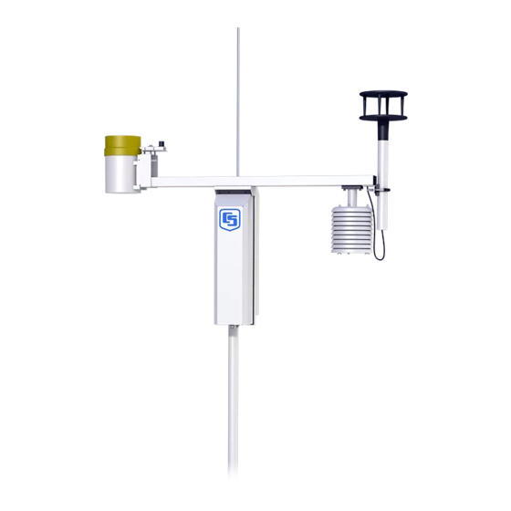
ET107 Weather Station Introduction The ET107 is an automated weather station designed for irrigation scheduling in turf grass and commercial agriculture applications. A properly programmed station calculates potential evapotranspiration (ETo), which is the amount of water lost from the soil due to evaporation and plant transpiration. Calculating the evapotranspiration rate can aid in the development of an irrigation schedule that provides sufficient water without overwatering. -
Page 11: Initial Inspection
Foam Layer ET107, Middle Packing Top Layer Foam Layer ET107, Bottom Layer Bottom Packing Foam Layer FIGURE 3-2. Shipping box packaging Check contents against invoice and shipping checklist (FIGURE 3-3, FIGURE 3-4) and contact Campbell Scientific immediately about any shortages. -
Page 12: Et107 With The Met One 034B-Etm Wind Sensor, Top Layer
Temp/RH Sensors Instruction Enclosure Wind Set Manual Cardboard Containing Wind Vane FIGURE 3-3. ET107 with the Met One 034B-ETM Wind Sensor, top layer Grounding and AC Transformer Mounting Template Grounding Wire Lightning Rod 2-Piece Pole and Cabling and Enclosure Desiccant Packs... -
Page 13: Quickstart
(Section 5.2, Base Foundation (p. 8) Install the ET107 pole (Section 5.3, Pole (p. 11) Place instrumentation enclosure on the ET107 pole, slide the enclosure to the top of the pole, and secure it with the correct orientation (Section 5.4, Enclosure (p. 14) Install the crossarm and sensors (Section 5.5, Crossarm and Sensor... -
Page 14: Supplies For Power And Communications Options
Pipe wrench (12 in) Handheld drill/driver with 3/8-inch hex driver bit Drill with 7/32-inch drill bit Supplies for Power and Communications Options AC Power Wire, conduit, and junction boxes as needed (FIGURE 4-1). FIGURE 4-1. ET107 pole installation with currently-available AC power option... -
Page 15: Installation
(Anixter pn F-02P22BPN (phone 847-677-2600)) or equivalent type cable (FIGURE 4-1). Radio Antenna for the ET107 station (Yagi antenna recommended). PS24 Power Supply and mounting kit with hangar if not using ac power (Appendix C, PS24 24 Ah Power Supply and 10 x 12 inch Enclosure (p. -
Page 16: Temperature And Relative Humidity
ET107 Weather Station FIGURE 5-1. Effect of structure on wind flow 5.1.2 Temperature and Relative Humidity Sensors should be located over an open, level area at least 9 m (29.5 ft) (EPA) in diameter. The surface should be covered by short grass, or where grass does not grow, the natural earth surface. -
Page 17: Soil Temperature
5.0 cm, 10.0 cm, 50.0 cm, 100.0 cm (2 in, 4 in, 19.7 in, 39.4 in) (WMO) Base Foundation 5.2.1 Supplied Components for Base Foundation The following components included with the ET107 are used to install the base: (3) 5/8-inch anchor L-bolts... -
Page 18: Cut-Away View Shows Anchor Bolt And Conduit Placement In Cement Pad
ET107 Weather Station Dig a hole 2-feet-by-2-feet-by-2 feet. Lighter soils may require a deeper hole. About 20 inches below the top of the hole, gouge a small cavity in one wall of the hole. The cavity should be about 4 inches deep and just large enough in diameter to insert one end of the conduit. -
Page 19: Ac Power Installation Procedure
Connect a two-conductor cable to the secondary terminals of the power supply. Route the cable from the power supply to the ET107 enclosure according to local electrical codes. Splice the incoming two-conductor cable to the power cable provided with the station. -
Page 20: Pole
Connector Standoff FIGURE 5-4. Position of bulkhead connectors Pole 5.3.1 Supplied Components for Pole Installation The following components included with the ET107 are used to install the pole: (1) upper pole section (tapered) (1) lower pole section (6) 5/8-inch washers... -
Page 21: Pole Installation Procedure
ET107 Weather Station 5.3.2 Pole Installation Procedure The pole provides a support structure for mounting the ET107 weather station components. The pole is designed to withstand winds of 100 mph. The lightning rod assembly is attached after the instrumentation enclosure is installed. -
Page 22: Pole Grounding
ET107 Weather Station Electrical fish tape will help. Leave approximately two feet of the supplied power and communication cable hanging out of the top of the pole. Secure all wiring so it doesn’t slip back down through the pole. NOTE Solar panel and radio frequency (RF) options will not have power or communication cables. -
Page 23: Enclosure
ET107 Weather Station Tighten the set screw (FIGURE 5-6). Loosen the ground rod clamp. Insert the 4 AWG wire. Tighten the clamp (FIGURE 5-6). 4 AWG Wire Ground Rod FIGURE 5-6. Close-up of ground rod and 4 AWG cable Enclosure... -
Page 24: Crossarm And Sensor
(p. D-2) exploded view of the crossarm. 5.5.1 Supplied Components for Crossarm and Sensor Installation (1) ET107 Crossarm with Sensors (FIGURE 5-8) (1) Met One 034B or WindSonic Wind Sensor (1) White Mounting Shaft for 034B or WindSonic (1) Radiation Shield... -
Page 25: Crossarm Installation Procedure
Radiation Shield Ground FIGURE 5-8. ET107 instrumentation mounted on the ET107 pole 5.5.2 Crossarm Installation Procedure The crossarm needs to be installed after the enclosure is mounted on the pole. You may need to temporarily remove the communications option. Mount the crossarm as shown in FIGURE without the wind sensor attached. -
Page 26: Rh And Temperature Radiation Shield Installation Procedure
ET107 Weather Station FIGURE 5-9. ET107 crossarm mounting Adjust the bolts at the base of the pole to vertically level the top section of the mounting pole. Remove the front lid and the protective connector cover from the back of the enclosure by loosening the one Phillips screw at the bottom of the cover. -
Page 27: Temperature/Relative Humidity Sensor With Yellow Protective Cap
ET107 Weather Station Adapter Temperature and RH Sensor Yellow Cap (remove) Radiation Shield FIGURE 5-10. Temperature/relative humidity sensor with yellow protective cap Temperature and RH Sensor without Cap FIGURE 5-11. Temperature/relative humidity sensor without yellow protective cap Insert the temperature/relative humidity into the radiation shield until it... -
Page 28: Wind Sensor (Wind Sensor Option -Mw)
ET107 Weather Station Attach the radiation shield to the underside of the crossarm using the two knurled thumb screws from step 1. Plug cable into the TEMP/RH connector on the enclosure. Ensure that the plug is completely seated on the connector and the locking ring is turned a quarter revolution clockwise. -
Page 29: Mounting To Pipe
ET107 Weather Station Wind Vane Counter Weight Shoulder Screw South Alignment Sticker Mounting Alignment Pipe Screw FIGURE 5-13. 034B mounting to pipe WARNING The wind vane can be easily damaged if dropped or bent. Leave the wind vane in the protective cardboard sleeve until it’s ready to be installed. -
Page 30: Windsonic 2-D Ultrasonic Wind Sensor (Wind Sensor Option -Gw)
5.5.5 WindSonic 2-D Ultrasonic Wind Sensor (Wind Sensor Option –GW) When the WindSonic1-ET is added to the ET107, a jumper setting must be changed (Section 5.5.5.1, Changing the Jumper (p. 21) -
Page 31: Screws That Secure The Electronics Cover
ET107 Weather Station Loosen Screws FIGURE 5-14. Screws that secure the electronics cover Remove the electronics cover to expose the printed circuit board (PCB) (FIGURE 5-15). Lift Here FIGURE 5-15. Removal of the electronics cover... -
Page 32: Windsonic Attachment To Crossarm
ET107 Weather Station 5. Move the jumper at the top of the PCB so that it is placed over the center and right pins (FIGURE 5-16). New Jumper Position FIGURE 5-16. Jumper set for WindSonic1 Replace electronics cover. Tighten screws. - Page 33 ET107 Weather Station FIGURE 5-17. WindSonic mounting shaft Slide the connector and cable up through the center of the mounting shaft. Plug the cable into the sensor. The connector has a key and needs to be pushed in then rotated clockwise to lock it in place (FIGURE 5-18).
-
Page 34: Rain Gage
ET107 Weather Station Center the WindSonic over the three threaded screw holes on the mounting shaft and screw it in place using the three Phillips screws taken off the shaft in step 1. Slide the shaft and sensor back through the U-bolt. -
Page 35: Pyranometer
ET107 Weather Station Put the gold funnel back on the top of the rain gage after leveling has been completed. Plug the cable in the RAIN/PRECIP connector on the enclosure. Ensure that the plug is completely seated on the connector and the locking ring is turned a quarter revolution clockwise. -
Page 36: 107-Lc Or 108-Lc Soil Temperature Sensor (Optional)
5.5.5.1, Changing the Jumper (p. 21) NOTE Jumper is set at the factory if the CS616 is ordered with the ET107 station. Bury the conduit from the weather station to the soil measurement site. Route the sensor cable through the conduit. -
Page 37: Sensor Connections
ET107 Weather Station NOTE The cable is waterproof but not armored. Therefore, Campbell Scientific recommends routing the cable through conduit, especially if rocky soils or rodents are present. Bury the conduit from the weather station to the soil measurement site. -
Page 38: Sensor Verification And Clock Set
FIGURE 5-22. Connecting sensor cabling to enclosure 5.5.12 Sensor Verification and Clock Set Send the weather station program to the station using Campbell Scientific software such as VisualWeather, PC400, or LoggerNet. The station can be accessed directly using a CR1000KD keypad display at the weather station. -
Page 39: Communication Peripherals
SDC7 or SDC8: 115,200 bps 5.6.1 Direct Connect to ET107 Station The ET107 station does not require an interface device for direct RS-232 communication. The inside of the enclosure has a RS-232 and CS I/O port available for communication (see FIGURE 5-23). Most standard... -
Page 40: Phone Modem
FIGURE 5-23. Close-up of the terminals and 9-pin ports in the ET107 (battery not shown) 5.6.2 Phone Modem Phone modems enable communications between the ET107 enclosure and a Hayes compatible modem at your computer over a dedicated phone line. -
Page 41: Internal Installation Of Phone Modem
ET107 Weather Station 5.6.2.1 Internal Installation of Phone Modem NOTE If the phone modem was ordered with the ET107, skip this section and go directly to Section 5.6.2.2, External Installation of Phone Modem (p. 33) For installation inside the ET107 enclosure, the following components are... -
Page 42: External Installation Of Phone Modem
5.6.3.1 Internal Installation of Short Haul Modem NOTE If the short haul modem was ordered with the ET107, skip this section and go directly to Section 5.6.3.2, External Installation of Short Haul Modem (p. 35) - Page 43 ET107 Weather Station Rad Short Haul Modem Ribbon Cable SC932C 12-inch 4-Wire Patch Cable FIGURE 5-25. Short-haul modem mounting and connection (battery not shown) Mount the Rad / SC932C mounting bracket into the enclosure with the three pre-threaded screws provided.
-
Page 44: External Installation Of Short Haul Modem
See FIGURE 5-25 for close-up FIGURE 5-26. Short-haul modem wiring diagram Components of the short haul kit used for external connections at the ET107 enclosure are: (1) 20 ft 4-Wire Patch Cable (2) 2 Direct Burial Splice Kits (1) Length of User Supplied Wire (Supplier: Anixter, pn F-02P22BPN,... -
Page 45: Radio
10-watt solar panel can be used but days without sunlight and winter months with little sunlight should be considered. The ET107 station comes with a 7 amp-hour battery that is NOT designed to handle deep discharge. Discharging the battery below 11 Vdc may require battery replacement. -
Page 46: Internal Installation Of The Radio
5.6.4.2 Internal Installation of the Radio NOTE If the ET107 was ordered with a radio kit, skip this section and go directly to Section 5.6.4.3, External Installation of the Radio (p. 38) -
Page 47: External Installation Of The Radio
ET107 Weather Station Ribbon Cable Antenna Cable FIGURE 5-27. Radio mounted in the ET107 (battery not shown) Connect the long 9-pin female end of the ribbon cable to the CS I/O port on the radio. Screw the connector to the radio using the provided two screws (FIGURE 5-28). - Page 48 ET107 Weather Station Remove the sensor cable cover off of the back of the enclosure by loosening the thumb screw at the bottom of the cover and swinging the cover back and down. The top of the cover has a tab that fits in to the rectangular hole on the back of the sensor crossarm.
- Page 49 ET107 Weather Station Use the 2.125 stainless steel U-bolt to attach the adjustable angle mounting bracket to the pole. Depending on the size of the antenna, position the bracket directly below, or above, the enclosure top mounting bracket. The top of an omnidirectional antenna should not be higher than the top of the lightning rod.
- Page 50 ET107 Weather Station Mount the saddle bracket to the adjustable angle mount bracket by inserting the ends of the bracket through the quarter circle notches (FIGURE 5-33). Put a flat washer, lock washer, and a silicon bronze nut, in that order, on the ends of the saddle bracket.
- Page 51 ET107 Weather Station FIGURE 5-34. Yagi antenna mounted to saddle bracket Orient the Yagi antenna so it’s aimed at the base antenna. You may have to flip the adjustable angle bracket over to get the antenna and saddle bracket to point correctly in the vertical direction.
- Page 52 ET107 Weather Station Wire Ties FIGURE 5-35. Wire tie antenna cable to Yagi antenna and to pole Wire tie the antenna cable to the pole. Wire Tie Wire Tie FIGURE 5-36. Wire tie locations for omnidirectional antenna installation Clean up the wire ties and put the cable cover back on.
-
Page 53: Base Radio Installation
ET107 Weather Station 5.6.4.4 Base radio installation: The base radio kit comes with the following items. (1) RS-232 serial data cable with 6 ft of cable (1) wall adapter: 100 to 240 Vac, 50 to 60 Hz input to 12 Vdc... -
Page 54: Et107 Cell Phone Accessory Kit
FIGURE 5-38. A base radio installed in an office 5.6.5 ET107 Cell Phone Accessory Kit This kit includes hardware for installing a cellular phone to an ET107 weather station. The cellular modem and antenna are ordered separately. 5.6.5.1 Cellular Modems Available from Campbell Scientific Campbell Scientific currently offers cellular modems that provide serial and Ethernet connectivity to numerous cellular networks. -
Page 55: Antenna
PS24. 5.6.5.2 Antenna Campbell Scientific recommends the 2 dBd 4G/3G Multiband Omnidirectional Antenna for the cell modem in an ET107 station. This antenna is ideally suited for use with 4G and 3G cellular gateways. NOTE Mounting hardware that comes in the box with some antennas will not be used. - Page 56 Attach the power cable to the cellular modem. Insert the red wire on the power cable into either the SW-12 or 12V terminal on the ET107 (FIGURE 5-39). Insert the black wire on the power cable into the ⏚ terminal on the ET107 (FIGURE 5-39). NOTE...
-
Page 57: External Installation Of A Cellular Modem
Mounting hardware that comes in the box with the antenna will not be used. To mount the antenna onto the ET107 pole, the cell phone accessory kit contains the following hardware, which is the same hardware used in the spread spectrum radio kit: (1) antenna cable –... -
Page 58: Nl241 Wi-Fi Accessory Kit
5.6.6.1 Antenna Campbell Scientific recommends the 2.4 GHz 5.8 dBd omnidirectional antenna with the NL241 Wi-Fi modem in an ET107 station. This antenna provides a 5.8 dBd gain. The Wi-Fi kit provides the hardware needed to mount the antenna to the ET107 pole. -
Page 59: External Installation Of The Wi-Fi Modem
5.6.6.4 External Installation of the Wi-Fi Modem The 2.4 GHz/5.8 dBd Omnidirectional Wi-Fi Antenna should have been ordered with the kit. To mount the antenna onto the ET107 pole, the Wi-Fi accessory kit contains the following hardware: (1) antenna cable, 59 inch (1) adjustable angle antenna mounting bracket (1) 5/16-18 x 2.125 stainless steel U-bolt... -
Page 60: Lightning Rod Installation
ET107 Weather Station Lightning Rod Installation Install lightning rod as shown in FIGURE 5-41 and FIGURE 5-42. Carefully mount the lightning rod clamp to the top of the pole (FIGURE 5-41). Position the clamp so it won’t interfere with the connector cover. -
Page 61: Solar Panel Installation
ET107 Weather Station Strip 2.54 cm (1 in) from both ends of the 23 cm (9 in) piece of 10 AWG green ground wire. Insert one end into the enclosure ground lug located at the top back of the enclosure. -
Page 62: Latitude And Solar Panel Tilt Angle
ET107 Weather Station TABLE 5-1. Latitude and Solar Panel Tilt Angle Latitude Tilt Angle (α) 0 to 10 degrees 10 degrees 11 to 20 degrees Latitude + 5 degrees 21 to 45 degrees Latitude + 10 degrees 46 to 65 degrees Latitude + 15 degrees >65 degrees... -
Page 63: Battery Installation
ET107 Weather Station Battery Installation Power Switch Battery installation diagram FIGURE 5-45. PS150 with lid open Move the PS150 power switch to the OFF position (FIGURE 5-45). Remove the cover from the PS150 by sliding the latch up at one end of the cover and sliding the cover down and out (FIGURE 5-45). -
Page 64: Restraining Cables And Sealing/Desiccating Enclosure
ET107 Weather Station FIGURE 5-46. PS150 to ET107 enclosure wiring 5.10 Restraining Cables and Sealing/Desiccating Enclosure 5.10.1 Restraining Cables Loosely wire tie power, communication, and grounding cable to the wire tie harness at the top of the back of the station (FIGURE 5-47). Do NOT clip back the wire tie at this time. -
Page 65: Sealing And Desiccating The Enclosure
(FIGURE 5-48). 5.10.2 Sealing and Desiccating the Enclosure The ET107 enclosure is supplied with two desiccant packs. The desiccant maintains a low humidity in the enclosure to minimize the chance of condensation on the instrumentation. Desiccant should be changed when the internal enclosure humidity sensor measures 50% or higher. -
Page 66: Et107 Software
A variety of different software packages are available to work with the ET107 station. This section introduces software packages that can be used with the ET107 station. It is not the goal to fully explain capabilities of each package. All software packages mentioned below come with extensive help files. -
Page 67: Maintenance, Troubleshooting, And Schematics
Campbell Scientific website www.campbellsci.com/downloads. VisualWeather version 3.0 or higher is designed to work with the ET107 station and can be used to create programs, monitor present conditions, collect data, and create reports and graphs. VisualWeather is a user-friendly program, requiring no datalogger experience to use it. -
Page 68: Solar Panel
Rinse with clean water. 6.1.3 Desiccant Humidity is monitored inside the ET107 enclosure using the Elan HM2000 RH sensor that is incorporated in the enclosure. Change the desiccant packs when the enclosure RH exceeds 50%. The enclosure RH sensor should be changed approximately every five years. - Page 69 Assistance page). 1 year Replace the wind speed (anemometer) bearings on the 034B-ET. • Return the sensor to Campbell Scientific for bearing replacement (see page). Assistance Replace reed switch the 034B-ET if needed. Return the sensor to • Campbell Scientific for bearing replacement (see Assistance page).
- Page 70 Replace vane potentiometer of the 034B-ET if needed (refer to • www.campbellsci.com/order/034b-et for part number and price). To send the sensor to Campbell Scientific for potentiometer replacement, refer to the Assistance page. Replace enclosure gasket if necessary. Refer to the...
-
Page 71: Procedure For Removing Rh Chip
SRAM when the module is not powered. The CR1000M does not draw power from the lithium battery while it is powered by a 12 Vdc supply. In an ET107 stored at room temperature, the lithium battery should last approximately 10 years (less at temperature extremes). -
Page 72: Troubleshooting
Cycle the power to the datalogger by switching the PS150 power supply to OFF then to ON, or by disconnecting and reconnecting the battery plug. The keypad should power up and the Campbell Scientific logo and text should appear on the display. -
Page 73: Nan Or ±Inf Displayed In A Variable
ET107 Weather Station 2. Check the cable(s) between the serial port and the modem. If cables have not been purchased through Campbell Scientific, check for the following configuration using an ohm meter: 25-Pin Serial Port Computer End Modem End 9-Pin Serial Port... -
Page 74: Nan Or ±Inf Stored In A Data Table
Socketed connectors on the back of the enclosure are the mirror images of what’s shown. 6.3.1 Sensor Schematics Schematics of ET107 sensors and associated connectors are provided in FIGURES through for help in troubleshooting. - Page 75 ET107 Weather Station FIGURE 6-2. Schematic of HMP60-ETS RH and Temperature Probe and connector Temp/RH FIGURE 6-3. Schematic of 034B-ET Wind Speed and Direction Probe and connector WS/WD...
- Page 76 ET107 Weather Station FIGURE 6-4. Schematic of WindSonic1-ET Wind Sensor, soil temperature sensor (107-LC or 108-LC), and connector Temp/Sonic FIGURE 6-5. Schematic of CS305-ET Solar Radiation Sensor and connector Solar Radiation...
- Page 77 ET107 Weather Station NOTE The ET106 used a Licor LI200X-ET Solar Radiation Sensor with OHM readings of 450 to 650. FIGURE 6-6. Schematic of TE525-ET Rain Sensor and connector Rain (Precip) FIGURE 6-7. Schematic of 107-LC or 108-LC Temperature Sensor or...
-
Page 78: Power Schematics
ET107 Weather Station FIGURE 6-8. Schematic of CS650-LC or CS655-LC 6.3.2 Power Schematics 18 to 24 VRMS or 15 to 40 Vdc Solar Panel Power PS150 Charger/Regulator (Solar Panel+) Charge Black Charge (Solar Panel-) Power Note: PS150 Charger/Regulator is not sensitive to polarity. -
Page 79: Communication Modems Schematics
ET107 Weather Station 6.3.3 Communication Modems Schematics FIGURE 6-10. Schematic of short haul or phone modem and connector COMM... -
Page 80: Determining True North And Wind Sensor Orientation
Appendix A. Determining True North and Wind Sensor Orientation The orientation of the WindSonic “North Arrow Markers” is found by reading a magnetic compass and applying the site-specific correction for magnetic declination; where the magnetic declination is the number of degrees between True North and Magnetic North. -
Page 81: A Declination Angle West Of True North (Negative) Is Subtracted From 0 (360) Degrees To Find True North
Appendix A. Determining True North and Wind Sensor Orientation Declination angles east of True North are considered negative, and are subtracted from 360 degrees to get True North as shown FIGURE (0° and 360° are the same point on a compass). Declination angles west of True North are considered positive, and are added to 0 degrees to get True North as shown in FIGURE A-3. -
Page 82: Online Magnetic Declination Calculator
Appendix A. Determining True North and Wind Sensor Orientation A.1 Online Magnetic Declination Calculator The magnetic declination calculator web calculator published by NOAA’s Geophysical Data Center is available at the following url: www.ngdc.noaa.gov/geomagmodels/Declination.jsp. This web page calculates declination based on the latitude and longitude. You can look up your site's latitude and longitude by entering the Zip Code or the Country and City, and then clicking the Get &... - Page 83 Appendix A. Determining True North and Wind Sensor Orientation FIGURE A-5. NOAA calculated declination using HTML result format...
-
Page 84: Et107 Maintenance Log
Appendix B. ET107 Maintenance Log Station Installation Date: ___________________ CLEAN/INSPECT RAIN GAGE SENSOR CLEAN/INSPECT RAIN GAGE SENSOR (Recommended - Weekly) (Recommended - Weekly) Date OK/Comments Date OK/Comments... - Page 85 Appendix B. ET107 Maintenance Log CLEAN/INSPECT SOLAR RADIATION SENSOR REPLACE WIND SPEED BEARINGS AND (Recommended - Monthly) REED SWITCH (Recommended - Yearly) Date OK/Comments Date OK/Comments REPLACE RH CHIP IN THE HMP60-ETS TEMP/RH SENSOR (Recommended - Yearly) Date OK/Comments REPLACE DESICCANT BAGS (QTY - 2)
-
Page 86: Ps24 24 Ah Power Supply And 10 X 12 Inch Enclosure
The battery should be recharged via ac power or solar power. An SP10 10-W solar panel, SP20 20-W solar panel, or wall charger is typically used to recharge the battery. The environmental enclosure is mounted to the ET107 pole using the mounting kit with hanger. -
Page 87: Enclosure Supply Kit
Appendix C. PS24 24 Ah Power Supply and 10 x 12 inch Enclosure FIGURE C-2. 24 Ah battery and battery cable FIGURE C-3. Enclosure supply kit... -
Page 88: Installation
Appendix C. PS24 24 Ah Power Supply and 10 x 12 inch Enclosure C.2 Installation CAUTION The PS24 is purposely shipped without the battery mounted in its bracket. Do not install the battery until instructed to do Place the top enclosure bracket on the pole at approximately 40 inches above the bottom of the pole. - Page 89 FIGURE shows the top and bottom brackets correctly positioned on the ET107 pole. FIGURE C-5. Both strut clamps and brackets on ET107 pole...
- Page 90 Appendix C. PS24 24 Ah Power Supply and 10 x 12 inch Enclosure Hook the enclosure on the top bracket as shown in FIGURE C-6. FIGURE C-6. Top clamp hook side up...
-
Page 91: Enclosure Mounted On Et107 Pole
The bottom enclosure bracket should slide between the top lip of the bottom strut mount bracket and the notch directly below. Move the bottom bracket if necessary, then bolt the bottom bracket down (see FIGURE C-7). CAUTION Do NOT over tighten the bottom bracket. FIGURE C-7. Enclosure mounted on ET107 pole... - Page 92 Appendix C. PS24 24 Ah Power Supply and 10 x 12 inch Enclosure The bottom enclosure bracket has a small metal locking mechanism. Push up on the small Phillips screw underneath the mechanism and slide it to the left. Once in place, put a small wire tie in the hole to the right of the locking mechanism (see FIGURE C-8).
- Page 93 FIGURE C-9. Fully mounted solar panel Throw a blanket or box over the solar panel to prevent any voltage output. Route the solar panel cable and power cable coming from the main ET107 enclosure into the conduit at the bottom of the 10-inch-by-12-inch enclosure.
- Page 94 Appendix C. PS24 24 Ah Power Supply and 10 x 12 inch Enclosure 11. Wire the charging source (solar panel or ac source) into the two CHG terminals on the CH150 or CHARGE terminals on the PS100 and PS150 (TABLE C-1). TABLE C-1.
- Page 95 NOTE The power cable that carries the regulated 12 Vdc power from the regulator in the external enclosure to the ET107 station enclosure has a two-pin connector on one end and tinned wires on the other. 13. Toggle the power switch on the regulator (CH100, PS100, CH150, or PS150) to the OFF position.
- Page 96 Pink on the humidity indicator card means it’s time to change the desiccant. Change the desiccant at least every year. However, it’s often wise to change the desiccant every six months. 23. Close the lids on the external enclosure and the ET107 enclosure. C-11...
-
Page 97: Exploded Views
Appendix D. Exploded Views D.1 Enclosure Exploded View... -
Page 98: Crossarm Exploded View
Appendix D. Exploded Views D.2 Crossarm Exploded View... - Page 99 Appendix E. Default Programs CRBasic Example E-1. Program for ET107 with WindSonic StationName(ET107_WindSonic) 'Datalogger status information Public BattVolt Public LogrTmpC Public Encl_RH Public WatchDog Public Overruns Public LowVolts Public LiBattV 'WindSonic RS232 variables Public WindSpd_ms Public WindSpd_mph Public WindDir WC_WSmph...
-
Page 100: Default Programs
Appendix E. Default Programs Minimum(1, RelHum, FP2, 0, False) Average(1, SlrRad_W, FP2, 0) Maximum(1, SlrRad_W, FP2, 0, False) Maximum (1,DewPntC,FP2,False,False) Minimum (1,DewPntC,FP2,False,False) Maximum (1,WindChilC,FP2,False,False) Minimum (1,WindChilC,FP2,False,False) Maximum (1,HeatIndxC,FP2,False,False) Minimum (1,HeatIndxC,FP2,False,False) EndTable DataTable (STATS,TRUE,168) DataInterval (0,60,Min,10) Totalize (1,one,IEEE4,disable_flag) FieldNames ("n_TOT") Totalize (1,one,IEEE4,diag<>1) FieldNames ("diag_1_TOT") - Page 101 (HeatIndxC = NAN) Then HeatIndxC = AirTempF HeatIndxC = (5/9) * (HeatIndxC - 32) CallTable VW_Hourly CallTable STATS NextScan EndProg CRBasic Example E-2. Program for ET107 with 034B StationName(ET107_034B) 'Datalogger status information Public BattVolt Public LogrTmpC Public Encl_RH Public WatchDog...
- Page 102 Appendix E. Default Programs 'CONNECTOR: TEMP/RH 'HMP60-ET Public AirTempC Public AirTempF Public RelHum 'CONNECTOR: Solar Radiation Public SlrRad_W 'Miscellaneous variables and calculations Public DewPntC Public HeatIndxC Public WindChilC DataTable(VW_Hourly,true,-1) DataInterval(0,60,Min,10) Maximum(1, BattVolt, FP2, 0, False) Minimum(1, BattVolt, FP2, 0, False) Maximum(1, Encl_RH, FP2, 0, False) Minimum(1, Encl_RH, FP2, 0, False) Maximum(1, LogrTmpC, FP2, 0, False)
- Page 103 Appendix E. Default Programs Rain24Ttl = 0 n = 24 To 2 Step Rain(n) = Rain(n-1) Rain24Ttl = Rain24Ttl + Rain(n) Next RainHrTtl = 0 EndIf PortSet(9, 1) Delay(0,200,MSEC) VoltSe(AirTempC, 1, mV2500, 2, False, 0, _60Hz, 0.1, -40) VoltSe(RelHum, 1, mV2500, 1, False, 0, _60Hz, 0.1, 0) If (RelHum >= 100) (RelHum <...
-
Page 104: Step-Down Transformer Installation
User-Supplied Valve Box Swept Elbow Conduit FIGURE F-1. ET107 pole installation with step-down transformer NOTE User supplies valve box at base of station and weatherproof enclosure for transformer (FIGURE F-1). The ac power option at one time included a 120 Vac to 16 Vac step-down transformer. - Page 105 Appendix F. Step-down Transformer Installation Route the cable from the transformer to the ET107 enclosure according to local electrical codes. Splice the incoming two-conductor cable to the power cable provided with the station. Use the direct burial splice kit when splices are in a valve box or buried.
- Page 106 Campbell Scientific Worldwide Offices Australia Germany Location: Garbutt, QLD Australia Location: Bremen, Germany Email: Email: info@campbellsci.com.au info@campbellsci.de Website: www.campbellsci.com.au Website: www.campbellsci.de Brazil South Africa Location: São Paulo, SP Brazil Location: Stellenbosch, South Africa Email: andread@campbellsci.com.br Email: sales@csafrica.co.za Website: Website: www.campbellsci.com.br www.campbellscientific.co.za...
Need help?
Do you have a question about the ET107 and is the answer not in the manual?
Questions and answers