
Subscribe to Our Youtube Channel
Related Manuals for Campbell CM10


Summary of Contents for Campbell CM10
- Page 1 CM6/CM10 Tripod Weather Station Installation Manual Revision: 7/10 C o p y r i g h t © 1 9 9 3 - 2 0 1 0 C a m p b e l l S c i e n t i f i c , I n c .
- Page 2 (12) months from date of shipment unless specified otherwise. Batteries have no warranty. Campbell Scientific, Inc.'s obligation under this warranty is limited to repairing or replacing (at Campbell Scientific, Inc.'s option) defective products. The customer shall assume all costs of removing, reinstalling, and shipping defective products to Campbell Scientific, Inc.
-
Page 3: Table Of Contents
CM6/CM10 Table of Contents PDF viewers note: These page numbers refer to the printed version of this document. Use the Adobe Acrobat® bookmarks tab for links to specific sections. 1. Preparation and Siting ..........1-1 1.1 Installation Tasks .................. 1-1 1.1.1 Indoors ..................1-1 1.1.2 Outdoors.................. - Page 4 CM6/CM10 Table of Contents 3.3.5 RF500M RF Modem and RF310-Series Transceivers ....3-12 3.3.5.1 RF500M Modem Configuration ........3-12 3.3.5.2 RF500M RF Base Station..........3-13 3.3.5.3 Install Nearest Repeater/Field Station ......3-14 3.3.6 MD485 Multidrop Interface ............3-14 3.3.6.1 MD485 Multidrop Interface at the Datalogger ....3-14 3.3.6.2 MD485 Multidrop Interface at the Computer....
- Page 5 CM6/CM10Table of Contents 6.2 TroubleShooting ................... 6-3 6.2.1 No Response Using the Keypad ..........6-3 6.2.2 No Response from Datalogger through SC32B or Modem Peripheral ................6-3 6.2.3 NaN Displayed in a Variable ............6-4 6.2.4 Unreasonable Results Displayed in a Variable ......6-4 Figures 1.3-1.
- Page 6 CM6/CM10 Table of Contents 4.13-1. CS616 Water Content Reflectometer with #14383 Probe Insertion Guide ................4-15 4.14-1. 237 Leaf Wetness Sensor ............. 4-15 4.15-1. 257 Soil Moisture Sensor ............. 4-16 4.16-1. CS210 Installed on a CR1000 ............4-17 4.17-1. Magnetic Declination for the Contiguous United States ....4-18 4.17-2.
-
Page 7: Preparation And Siting
Section 1. Preparation and Siting 1.1 Installation Tasks 1.1.1 Indoors • Immediately upon receipt of your shipment… ⇒ Open shipping cartons. ⇒ Check contents against invoice. Contact CSI immediately about any shortages. • Several days prior to the planned installation date… ⇒... -
Page 8: Tools Required
Section 1. Preparation and Siting 1.2 Tools Required Tools required to install and maintain a weather station are listed below. 1.2.1 Tools for Tripod Installation Shovel Rake Open end wrenches: 3/8", 7/16", ½", (2) 9/16" Magnetic compass 6' Step ladder Tape measure (12') Level (12"... -
Page 9: Supplies For Power And Communications Options
Section 1. Preparation and Siting 1.2.3 Supplies for Power and Communications Options AC Power Wire, conduit, and junction boxes as needed Phone Modem Hayes compatible calling modem for PC Phone line to weather station or junction box Short-Haul Modem 4 Conductor communications cable from PC to weather station or junction box 6' copper ground rod and clamp for PC surge protection (optional) 1.3 Siting and Exposure CAUTION... -
Page 10: Precipitation
Section 1. Preparation and Siting Situations to avoid include: • large industrial heat sources • rooftops • steep slopes • sheltered hollows • high vegetation • shaded areas • swamps • areas where snow drifts occur • low places holding standing water after rains Standard measurement heights: 1.5 m ±... -
Page 11: Effect Of Structure On Wind Flow
Section 1. Preparation and Siting Standard measurement depths: 10.0 cm ± 1.0 cm (AASC) cm, 10.0 cm, 50.0 cm, 100.0 cm (WMO) FIGURE 1.3-1. Effect of Structure on Wind Flow References EPA, (1987). On-Site Meteorological Program Guidance for Regulatory Modeling Applications, EPA-450/4-87-013. Office of Air Quality Planning and Standards, Research Triangle Park, North Carolina 27711. - Page 12 Section 1. Preparation and Siting...
-
Page 13: Cm6/Cm10 Tripod Installation
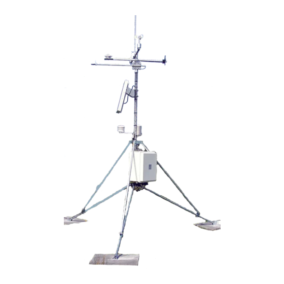
Section 2. CM6/CM10 Tripod Installation The CM6 and CM10 tripods provide a support structure for mounting weather station components. Figure 2-1 shows a typical guyed CM10 tripod weather station equipped with instrumentation enclosure, meteorological sensors, and solar panel. FIGURE 2-1. CM10 Weather Station... -
Page 14: Specifications
Section 2. CM6/CM10 Tripod Installation 2.1 Specifications CM6 Tripod Maximum height (zero leg extension) 7.5 ft (2.3 m) Minimum height (full leg extension) 5.5 ft (1.7 m) Wind Load (Wind Sensors at 2 meters)* Maximum wind load 100 mph Gust survival 130 mph Tripod Leg Diameter (See Table 2-1) d = diameter... -
Page 15: Tripod Parts
Section 2. CM6/CM10 Tripod Installation 2.2 Tripod Parts Tripods are either shipped complete and mostly assembled (CM6 or CM10), or as a kit that requires the user to supply some parts (CM10K). If a preassembled CM6 or CM10 Tripod was ordered, the following parts should have been received: (1) Tripod Base Assemble (1) Mast Assembly... -
Page 16: Extending The Tripod Legs
Section 2. CM6/CM10 Tripod Installation attaches to the foot (Figure 2-2), measure up 23” on the CM10, or 26” on the CM6, and mark each leg with a felt tip pen. 4. Each leg has a slide collar with a single bolt for loosening or tightening the collar (Figure 2-2). -
Page 17: Tripod Grounding
Section 2. CM6/CM10 Tripod Installation CROSSARM SENSOR MOUNT PYRANOMETER MOUNTING ARM FIGURE 2-3. Tripod and Component Orientation 2.4 Tripod Grounding Ground the tripod and shown in Figures 2-1, 2-4, and 2-5. 1. Drive the ground rod close to the center of the tripod using a fence post driver or sledge hammer. -
Page 18: Ground Rod And Clamp
Section 2. CM6/CM10 Tripod Installation Clamp 4 AWG Wire Ground FIGURE 2-4. Ground Rod and Clamp 3. Loosen the set screws in the two brass ground lugs attached to the center bracket of the tripod (Figure 2-5). Strip 1 inch of insulation from the other end of the 4 AWG wire and insert it into the lower ground lug. -
Page 19: Cm10 Guy Kit Installation
Section 2. CM6/CM10 Tripod Installation FIGURE 2-5. Tripod Ground Connections 2.5 CM10 Guy Kit Installation The CM10 Guy Kit is an option when purchasing the CM10 Tripod or CM10K Tripod Kit. It can be installed to improve the CM10 Tripod wind load rating. Table 2-3 lists items in the CM10 Guy Kit. -
Page 20: Guy Wire Installation
Section 2. CM6/CM10 Tripod Installation FIGURE 2-6. Guy Wire Installation 1. Construct an assembly consisting of the top plate, wire ropes, 3 thimbles, and 6 u-bolts. Place a thimble into each of the three small holes of the top plate. Twist each thimble slightly, as shown in Figure 2-7, to accomplish this. -
Page 21: Turnbuckle Assembly
Section 2. CM6/CM10 Tripod Installation 2. Slide the top plate down the crossarm mount so that it rests on the bell reducer. 3. Attach the 3 bottom plates to the tripod feet with the existing tripod foot bolts. Make certain that each bottom plate is oriented such that the second hole is above the tripod foot. -
Page 22: Sensor Mounting Brackets
Section 2. CM6/CM10 Tripod Installation 2.6 Sensor Mounting Brackets Mounting brackets provide a means of mounting the sensors to the tripod. Bracket mounting heights are referenced from the top of the bell reducer; orientation is shown in Figure 2-3. 2.6.1 Crossarm Mounting 2.6.1.1 CM202, CM204, CM206 Crossarms Attach the crossarm at the desired height via the provided u-bolts and nuts (Figure 2-9). -
Page 23: Gill Radiation Shields (41303-5A, 41003-5, 41005-5)
Section 2. CM6/CM10 Tripod Installation Lightning Rod REGCOMENDED Feed SENSORS Serial 27115 Portland Or USA REGCOMENDED Feed SENSORS Serial 27115 27115 Portland Or USA i a l 019ALU FIGURE 2-10. 019ALU Crossarm and Lightning Rod 2.6.2 Gill Radiation Shields (41303-5A, 41003-5, 41005-5) 1. -
Page 24: Cm225 Solar Radiation Mount With A Li2003S Leveling Base And Li200X Solar Radiation Sensor
Section 2. CM6/CM10 Tripod Installation FIGURE 2-11. CM225 Solar Radiation Mount with a LI2003S Leveling Base and LI200X Solar Radiation Sensor FIGURE 2-12. CM225 Attached to a Mast 2-12... -
Page 25: Instrumentation Installation
Section 3. Instrumentation Installation 3.1 Enclosure, Datalogger, Power Supply 3.1.1 Enclosure All instrumentation (datalogger, power supply, and communication peripherals) are mounted in the enclosure. A PVC bulkhead port is installed in the enclosure for routing the sensor and communication cables to the instrumentation. -
Page 26: An Enclosure With The "-Mm" Mounting Option Attaches To A Tripod Mast Via U-Bolts
Section 3. Instrumentation Installation FIGURE 3.1-1. An enclosure with the “-MM” mounting option attaches to a tripod mast via u-bolts. FIGURE 3.1-2. This exploded view shows the components of a “-MM” bracket. -
Page 27: Datalogger And Power Supply
Section 3. Instrumentation Installation FIGURE 3.1-3. An enclosure attached to a tripod mast. 3.1.2 Datalogger and Power Supply The datalogger includes hardware for mounting it to an enclosure backplate (see Figure 3.1-4). Either a BPALK or PS100 power supply is also typically housed in the enclosure if a CR800, CR850, or CR1000 is used. -
Page 28: Ps100 Rechargeable Power Supply
Section 3. Instrumentation Installation 3.1.4 PS100 Rechargeable Power Supply The PS100 houses a sealed monoblock rechargeable battery. To install the battery, loosen the two thumb screws and remove the cover. 1. With the PS100 power switch "OFF", insert the battery and plug the battery lead into the connector labeled "INT". -
Page 29: Cr1000 And Ps100 Mounted To An Enclosure Backplate
Section 3. Instrumentation Installation FIGURE 3.1-4. CR1000 and PS100 Mounted to an Enclosure Backplate FIGURE 3.1-5. SP10 Solar Panel... -
Page 30: Sensor Connection
Section 3. Instrumentation Installation 3.2 Sensor Connection 1. After the sensors have been mounted, route the sensor leads through the entry hole in the bottom of the enclosure and to the datalogger. Secure the leads to the left side of the enclosure using cable ties and tabs (Figure 3.2-1). Any excess cable should be neatly coiled and secured to the tabs. -
Page 31: Communication And Data Storage Peripherals
Section 3. Instrumentation Installation 3.3 Communication and Data Storage Peripherals One or more peripherals (i.e., CompactFlash modules, modems, etc.) can be mounted to the enclosure backplate (ENC12/14, ENC14/16, or ENC16/18 enclosures). 3.3.1 CFM100, NL115, or NL120 Connect the CFM100, NL115, or NL120 module to the peripheral port of a CR1000 or CR3000 datalogger (see Figure 3.3-1). -
Page 32: Cellular Transceivers
FIGURE 3.3-2. COM220 Modem with Surge Protector 3.3.3 Cellular Transceivers Campbell Scientific offers two digital cellular modems—the RavenXTV CDMA modem and the RavenXTG GPRS modem. Refer to our product brochure for information on choosing the right cellular modem for your weather station. -
Page 33: Srm-5A Rad Modem And Sc932A Interface
Section 3. Instrumentation Installation 3.3.4 SRM-5A Rad Modem and SC932A Interface Rad Modems enable communication between the datalogger and computer over 4-wire unconditioned telephone line, or cable with two twisted pairs of wires. The maximum distance between modems is determined by baud rate and wire gauge. -
Page 34: Srm-5A Rad Modem And Sc932A Interface
Section 3. Instrumentation Installation 3. Route the cable from the remote SRM-5A, and the cable from the SRM- 5A attached to the computer to the 6361. Connect the cables as shown in Figure 3.3-5. Strain relief the cables using cable ties and tabs. FIGURE 3.3-3. -
Page 35: Srm-5A Wiring
Section 3. Instrumentation Installation Datalogger Computer FIGURE 3.3-4. SRM-5A Wiring 3-11... -
Page 36: Rf500M Rf Modem And Rf310-Series Transceivers
Device Configuration Utility software is used to configure the RF500M modem. Device Configuration Utility is included with LoggerNet or it can be downloaded for free from the Campbell Scientific web site (http://www.campbellsci.com). The configuration options can be seen in the... -
Page 37: Rf500M Rf Base Station
Section 3. Instrumentation Installation the green configuration button on the RF500M either before or while connected to enable the settings in Device Configuration Utility. There are five configuration options for the RF500M 1. RF ID – Set the modem address with a value from 1-255. Each RF500M in the network must have a unique RF ID. -
Page 38: Install Nearest Repeater/Field Station
3.3.6 MD485 Multidrop Interface Campbell Scientific’s MD485 is an intelligent RS-485 interface that permits a PC to address and communicate with one or more dataloggers over a distance of 4000 ft. The distance between the datalogger and computer can be increased by combining it with a phone modem, Ethernet link, or spread spectrum radio. -
Page 39: Md485 Multidrop Interface At The Computer
Section 3. Instrumentation Installation 3.3.6.2 MD485 Multidrop Interface at the Computer 1. Connect the CABLE3CBL cable to one of the MD485’s RS-485 ports. 2. Attach one end of the #10873 RS-232 cable to the MD485’s RS-232 port. 3. Attach the other end of the #10873 RS-232 cable to the computer’s RS-232 port. -
Page 40: Enclosure Supply Kit
Section 3. Instrumentation Installation 2. Seal around the sensor leads where they enter the enclosure. Place a roll of putty around the sensor leads and press it around the leads and into the coupling to form a tight seal. 3. Remove the RH indicator card and two desiccant packs from the sealed plastic bag. -
Page 41: Sensor Installation
Section 4. Sensor Installation Sensor leads should be routed down the North side of the mast to the enclosure and secured with cable ties. 4.1 034B Met One Windset Mount the 034B to the CM202, CM204, or CM206 crossarm as shown in Figure 4.1-1. -
Page 42: And 05305 Rm Young Wind Monitors
Section 4. Sensor Installation 4.2 05103, 05103-45, 05106, and 05305 RM Young Wind Monitors Mount the Wind Monitor to the CM202, CM204, or CM206 crossarm as shown in Figure 4.2-1. 1. Attach the CM220 bracket on the crossarm via the U-bolt and nuts. 2. -
Page 43: 03002 Rm Young Wind Sentry Wind Set
Section 4. Sensor Installation 4.3 03002 RM Young Wind Sentry Wind Set The 03002 can be mounted directly to the mast, or to the CM202, CM204, or CM206 Crossarm. 4.3.1 03002 Mounted to the Mast 1. Slide the crossarm mounting bracket onto the mast. Orient the crossarm so the vane end points north, and tighten the band clamp (see Section 4.19 for final calibration). -
Page 44: Licor Silicon Radiation Sensors (Li200X, Li200S, Li190Sb)
Section 4. Sensor Installation 4.4 Licor Silicon Radiation Sensors (LI200X, LI200S, LI190SB) Mount the Radiation Sensor to the LI2003S Base and Leveling Fixture as shown in Figure 4.4-1. 1. Position the base of the sensor in the mounting flange on the LI2003S, and tighten the set screw with the allen wrench provided. -
Page 45: Temperature Probe
Section 4. Sensor Installation Mounting Clamp FIGURE 4.5-1. 107 Temperature Probe... -
Page 46: 107/108 Soil Temperature Probe
Section 4. Sensor Installation 4.6 107/108 Soil Temperature Probe 1. Select an undisturbed area of ground on the side of the tower that will receive the least amount of traffic. Route the sensor lead from the datalogger to the selected area. 2. -
Page 47: Hmp50 Temperature And Rh Probe
Section 4. Sensor Installation HMP50 Mounting Clamp FIGURE 4.7-1. HMP50 Temperature and RH Probe... -
Page 48: Hmp45C/Hmp35C Vaisala Temperature And Rh Probe
Section 4. Sensor Installation 4.8 HMP45C/HMP35C Vaisala Temperature and RH Probe Mount the probe inside the 41003-5 10-plate radiation shield as shown in Figure 4.8-1. 1. Loosen the split plastic nut on the base of the shield. Insert the probe and tighten the nut. -
Page 49: Cs100 Or Cs106 Barometric Pressure Sensor
Section 4. Sensor Installation 4.9 CS100 or CS106 Barometric Pressure Sensor Mount the CS100 or CS106 to the enclosure backplate. 1. Mount the barometer to the mounting plate using the two screws and grommets provided. 4.10 Texas Electronics Tipping Bucket Rain Gages (TE525, TE525WS, TE525MM) 1. -
Page 50: Tb4, Tb4Mm Or Cs700 Rain Gage
Section 4. Sensor Installation 4.11 TB4, TB4MM or CS700 Rain Gage The rain gage should be mounted in a relatively level spot that is representative of the surrounding area. The lip of the funnel should be horizontal and at least 30 inches above the ground. -
Page 51: Sr50A Sonic Ranging Sensor
Section 4. Sensor Installation 4.12 SR50A Sonic Ranging Sensor 4.12.1 Beam Angle When mounting the SR50A, the sensor's beam angle needs to be considered (see Figure 4.12-1). It is always best to mount the SR50A perpendicular to the intended target surface. The SR50A has a beam angle of approximately 30 degrees. -
Page 52: Reference Point
Section 4. Sensor Installation 4.12.2.1 Reference Point The front grill on the ultrasonic transducer is used for the reference for the distance values. Because it is difficult to measure from the grill one can use the outer edge of the plastic transducer housing see Figure 4.12-2. If this edge is used, simply add 8mm to the measured distance. -
Page 53: Sr50A Mounted To A Crossarm Via The 19517 Mounting Kit
Section 4. Sensor Installation FIGURE 4.12-3. SR50A Mounted to a Crossarm via the 19517 Mounting Kit FIGURE 4.12-4. The SR50A Mounted to the Crossarm Shown from Another Angle 4-13... -
Page 54: Cs616 Water Content Reflectometer
Section 4. Sensor Installation FIGURE 4.12-5. SR50A - Mounted using Nurail and C2151 Mounting Stem SR50A with 6-plate gill radiation shield – the picture below shows the SR50A stem attachment 4.13 CS616 Water Content Reflectometer Probe rods can be inserted vertically or horizontally into the soil surface, as shown in Figure 4.13-1, or buried at any orientation to the surface. -
Page 55: 237 Leaf Wetness Sensor
Section 4. Sensor Installation reporting the output in units of period will make it possible to apply your own calibration during post processing of data. FIGURE 4.13-1. CS616 Water Content Reflectometer with #14383 Probe Insertion Guide 4.14 237 Leaf Wetness Sensor Mounting and orientation considerations are left to the user to determine. -
Page 56: 257 Soil Moisture Sensor
Section 4. Sensor Installation 4.15 257 Soil Moisture Sensor 1. Soak the sensor end of the 257 in irrigation water for 12 to 14 hours. Allow the sensor to dry for 1 to 2 days after soaking and repeat the soak/dry cycle twice to improve sensor response. -
Page 57: Cs210 Enclosure Humidity Sensor
Section 4. Sensor Installation 4.16 CS210 Enclosure Humidity Sensor Mount the CS210 inside the environmental enclosure or onto a datalogger using the mounting block and the wire tie included with the sensor (Figure 4.16-1). ® NOTE The black outer jacket of the cable is Santoprene rubber. -
Page 58: National Geophysical Data Center Web Site
Section 4. Sensor Installation 1. Establish a reference point on the horizon for True North. 2. Sighting down the instrument center line, aim the nose cone, or counterweight at True North. Display the input location for wind direction using the *6 Mode of the datalogger, or, the Monitor Mode of LoggerNet with an on-line PC. -
Page 59: Declination Angles East Of True North Are Subtracted From 0 To Get True North
Section 4. Sensor Installation FIGURE 4.17-2. Declination Angles East of True North are Subtracted from 0 to get True North FIGURE 4.17-3. Declination Angles West of True North are Added to 0 to get True North 4-19... - Page 60 Section 4. Sensor Installation 4-20...
-
Page 61: Standard Software Installation
Section 5. Standard Software Installation Software required for a weather station consists of the datalogger program and a datalogger support software suite for Windows. 5.1 Datalogger Program The datalogger program operates the weather station. It programs the datalogger to measure sensors, process the measurements, and store data in the datalogger’s memory. - Page 62 Section 5. Standard Software Installation...
-
Page 63: Maintenance And Troubleshooting
Section 6. Maintenance and Troubleshooting These guidelines apply to several different Campbell Scientific weather stations. 6.1 Maintenance Proper maintenance of weather station components is essential to obtain accurate data. Equipment must be in good operating condition, which requires a program of regular inspection and maintenance. Routine and simple maintenance can be accomplished by the person in charge of the weather station. -
Page 64: Desiccant
RH inside the enclosure. Change the desiccant when either the card or the sensor read about 35% RH. Desiccant may be ordered through Campbell Scientific (DSC 20/4). Desiccant packs inside of the dataloggers do not require replacement under normal conditions. -
Page 65: Troubleshooting
E. Reset the datalogger by turning the power switch to "OFF", then to "ON" or disconnecting and reconnecting the battery. F. If still no response, call Campbell Scientific. 6.2.2 No Response from Datalogger through SC32B or Modem Peripheral At the datalogger: A. -
Page 66: Nan Displayed In A Variable
D. Make sure the Station File is configured correctly. E. Check the cable(s) between the serial port and the modem. If cables have not been purchased through Campbell Scientific, check for the following configuration using an ohm meter: 25-pin serial port:... - Page 68 Campbell Scientific Companies Campbell Scientific, Inc. (CSI) 815 West 1800 North Logan, Utah 84321 UNITED STATES www.campbellsci.com • info@campbellsci.com Campbell Scientific Africa Pty. Ltd. (CSAf) PO Box 2450 Somerset West 7129 SOUTH AFRICA www.csafrica.co.za • cleroux@csafrica.co.za Campbell Scientific Australia Pty. Ltd. (CSA)
Need help?
Do you have a question about the CM10 and is the answer not in the manual?
Questions and answers