
Related Manuals for Campbell RAWS-P


Summary of Contents for Campbell RAWS-P
- Page 1 RAWS-P Remote Automated Weather Station Revision: 6/10 C o p y r i g h t © 2 0 0 6 - 2 0 1 0 C a m p b e l l S c i e n t i f i c ,...
- Page 2 Warranty and Assistance The RAWS-P REMOTE AUTOMATED WEATHER STATION is warranted by Campbell Scientific, Inc. to be free from defects in materials and workmanship under normal use and service for twelve (12) months from date of shipment unless specified otherwise. Batteries have no warranty. Campbell Scientific, Inc.'s obligation under this warranty is limited to repairing or...
-
Page 3: Table Of Contents
RAWS-P Table of Contents PDF viewers note: These page numbers refer to the printed version of this document. Use the Adobe Acrobat® bookmarks tab for links to specific sections. 1. Introduction..............1 2. Getting Started.............2 3. Station Siting and Orientation ........5 3.1 General Description ..................5... - Page 4 RAWS-P Table of Contents 4.5 Barometric Pressure ................. 9 4.5.1 General Description, Barometric Pressure (part #CS100-QD) ..9 4.5.2 Wiring, Barometric Pressure (part #CS100) ........9 4.5.3 Troubleshooting, Barometric Pressure (part #CS100) ....10 4.6 Fuel Moisture and Fuel Temperature............. 10 4.6.1 General Description, Fuel Moisture/Fuel Temperature...
- Page 5 RAWS-P Table of Contents 9. References ..............22 9.1 Specifications, Equipment and Sensor............22 9.2 Siting References ..................22 9.3 RAWS Orientation .................22 9.3.1 Determining True North and Sensor Orientation......22 9.3.2 USGS Web Calculator ..............24 Figures 1-1. Color Coded, Keyed Connector Panel ............1 2-1.
- Page 6 RAWS-P Table of Contents...
-
Page 7: Introduction
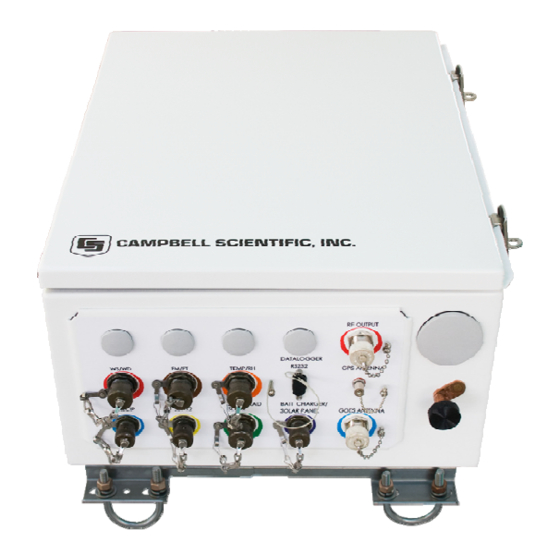
FIGURE 1-1. Color Coded, Keyed Connector Panel The RAWS-P comes with a generic program. Modifications to NOTE this generic program will require datalogger support software (LoggerNet or PC400) purchased from Campbell Scientific, Inc. -
Page 8: Getting Started
RAWS-P Remote Automated Weather Station 2. Getting Started NOTE Set up and test your station before field deployment. NOTE Keep this manual and the CR1000KD Keyboard Display with the RAWS. Review the station siting and orientation section before field deployment. If a problem is encountered, review the equipment wiring and troubleshooting sections in this manual. - Page 9 Power In CR1000 Wiring Panel FIGURE 2-1. Inside Environmental Enclosure (optional equipment shown) The RAWS-P comes with a generic program. Modifications to NOTE this generic program will require datalogger support software (LoggerNet or PC400) purchased from Campbell Scientific, Inc. Please contact a Campbell Scientific Application Engineer for programming assistance.
-
Page 10: Public Variables
RAWS-P Remote Automated Weather Station Use the CR1000KD Keyboard Display to see the NOTE “Public Variables” shown in Table 2-1. • Connect the CR1000KD Keyboard Display to the CS I/O connector (Figure 5.7-2) or SC12 Cable (Figure 2-1) • Press any key for the CR1000KD Power up Screen •... -
Page 11: Station Siting And Orientation
RAWS-P Remote Automated Weather Station 3. Station Siting and Orientation 3.1 General Description Selecting an appropriate site for the RAWS is critical in order to obtain accurate meteorological data. In general, the site should be representative of the general area of interest and away from the influence of obstructions such as buildings and trees. -
Page 12: Barometric Pressure
Verify that the sensor body is connected to the sensor head. Under the filter assembly, verify the sensors are connected but not touching. Try connecting a substitute sensor. Obtain a Return Material Authorization (RMA) number before returning this sensor to Campbell Scientific for repair. NOTE Consult the HMP45C-L manual for more information. -
Page 13: Rain Gage
Try connecting a substitute sensor. Obtain a Return Material Authorization (RMA) number before returning this sensor to Campbell Scientific for repair. NOTE Consult the TE525-L manual for more information. -
Page 14: Troubleshooting, Pyranometer (Part #Cs300-Lq)
Try connecting a substitute sensor. Obtain a Return Material Authorization (RMA) number before returning this sensor to Campbell Scientific for repair. NOTE Consult the CS300-L manual for more information. -
Page 15: 2-D Windsonic
Check the sensor cable. Disconnect the connector and look for damaged pins. Try connecting a substitute sensor. Should the 2-D sonic sensor be damaged, fails to output data, or sends a nonzero diagnostic, obtain a Return Material Authorization (RMA) number before returning this sensor to Campbell Scientific for repair. NOTE Consult the WINDSONIC4-L manual for more information. -
Page 16: Troubleshooting, Barometric Pressure (Part #Cs100)
CS205 mounts on the mounting stake with the CS505. 4.6.2 Wiring, Fuel Moisture/Fuel Temperature (part #CS515-LQ) The Campbell Scientific CS505 and CS205 sensors are combined into one connector (part#CS515-LQ). This sensor is internally wired from the RAWS connector panel to the CR1000 datalogger. This sensor is connected to the... -
Page 17: Troubleshooting, Fuel Moisture/Fuel Temperature (Part #Cs515-Lq)
Verify the CS505 sensor element is securely fastened. Try connecting a substitute sensor. Obtain a Return Material Authorization (RMA) number before returning the CS515-QD sensor to Campbell Scientific for repair. Consult the CS505-L, CS205 and 107-L manuals for more NOTE information. -
Page 18: Troubleshooting, Solar Panel (Part #Sp10/20-Lq)
RAWS-P Remote Automated Weather Station 5.1.3 Troubleshooting, Solar Panel (part #SP10/20-LQ) If a problem with the solar panel is suspected, the solar panel may be checked by measuring the voltage output from the solar panel. Check the voltage with a voltmeter connected between the two leads going to the CH100 charger/regulator “CHG”... -
Page 19: Wiring, 12 V Charger/Regulator (Part #Ch100)
RAWS-P Remote Automated Weather Station 5.2.2 Wiring, 12 V Charger/Regulator (part #CH100) The leads from the RAWS connector panel “BATT CHARGER/SOLAR PANEL” connector COLOR CODED PURPLE are wired to the CH100 “CHG” terminals. Polarity does not matter; either lead can be connected to either terminal. -
Page 20: Battery
5.4.1 General Description, GOES Transmitter (part #TX312) The High Data Rate GOES transmitter (part #TX312) shown in Figure 5.4-1 supports one-way communication, via satellite, from a Campbell Scientific datalogger to a ground receiving station. Satellite telemetry offers a convenient communication alternative for field stations where phone systems or RF systems are impractical or rendered unreliable after a tragedy to the local infrastructure. -
Page 21: Goes Transmitter
RAWS-P Remote Automated Weather Station The TX312 transmitter has two siting requirements for proper operation. The GOES antenna must have a clear view of the spacecraft. The GOES antenna is directional and should be aimed at the spacecraft. Both elevation and azimuth are unique to the location of the planet and must be set. -
Page 22: Wiring, Goes Transmitter (Part #Tx312)
Check the SC12 cable connection between the CR1000 wiring panel and the TX312. Press the TX312 diagnostic button to query the state of the transmitter. If problems persist, try a substitute. Obtain a Return Material Authorization (RMA) number before returning this equipment to Campbell Scientific for repair. NOTE Consult the TX312 manual for more information. -
Page 23: Wiring, Voice Radio Interface (Part #Vsp3)
--to-- CR1000 PC Board “C1” VSP3 “RADIO” RJ45 Connector --to-- UHF/VHF Radio* *Note: Maxon and Bendix King Radio cables are available from Campbell Scientific. 5.5.3 Troubleshooting, Voice Radio Interface (part #VSP3) If a problem with the voice radio interface (part #VSP3) is suspected, the VSP3 may be checked by measuring the +12 V and Ground terminal on the VSP3. -
Page 24: Cr1000 Keyboard/Display
RAWS-P Remote Automated Weather Station 5.6 CR1000 Keyboard/Display 5.6.1 General Description, CR1000 Keyboard/Display (part #CR1000KD) The CR1000 Keyboard/Display (part #CR1000KD) shown in Figure 5.6-1 is used to check datalogger status, display or plot sensor readings and stored values, and to enter numeric data or change port/flag state. The CR1000KD is powered from the CR1000 printed circuit board “CS I/O”... -
Page 25: Cr1000 Datalogger (Part #Cr1000)
RAWS-P Remote Automated Weather Station Obtain a Return Material Authorization (RMA) number before returning this equipment to Campbell Scientific for repair. NOTE Consult the CR1000 manual for more information. 5.7 CR1000 Datalogger (part #CR1000) 5.7.1 General Description, CR1000 Datalogger (part #CR1000) The CR1000 shown in Figure 5.7-1 provides sensor measurement,... -
Page 26: Wiring, Cr1000 Datalogger (Part #Cr1000)
A humidity indicator card (part #6571) and desiccant pack (part # 4905) may be ordered through Campbell Scientific. Desiccant packs inside of the datalogger do not require replacement under normal conditions. -
Page 27: Sensor And Equipment Maintenance
More difficult maintenance, such as sensor calibration, sensor performance testing (i.e., bearing torque), and sensor component replacement, generally requires a skilled technician, or send the instrument to Campbell Scientific. A station log should be maintained for each weather station that includes equipment model and serial numbers and maintenance that was performed. -
Page 28: Specifications, Equipment And Sensor
RAWS-P Remote Automated Weather Station 9. References 9.1 Specifications, Equipment and Sensor Specifications are available from our web site at http://www.campbellsci.com/index.cfm. For “sensors specifications,” click on “Products”, select “Sensors” and go to the sensor manual for specifications. For “equipment specifications”, enter the part # in the “Search”... - Page 29 RAWS-P Remote Automated Weather Station in Figure 9.3-3. Note that when a negative number is subtracted from a positive number, the resulting arithmetic operation is addition. For example, the declination for Longmont, CO is 10.1°, thus True North is 360° - 10.1°, or 349.9° as read on a compass. Likewise, the declination for Mc Henry, IL is -2.6°, and True North is 0°...
-
Page 30: A Declination Angle East Of True North (Positive) Is Subtracted From 360 (0) Degrees To Find True North
RAWS-P Remote Automated Weather Station FIGURE 9.3-2. A Declination Angle East of True North (Positive) is Subtracted from 360 (0) degrees to Find True North FIGURE 9.3-3. A Declination Angle West of True North (Negative) is Subtracted from 0 (360) degrees to Find True North 9.3.2 USGS Web Calculator... -
Page 31: Usgs Web Calculator
RAWS-P Remote Automated Weather Station FIGURE 9.3-4. USGS Web Calculator In the example above the declination for Logan, UT is 12º 24′ or 12.4º. As shown in Figure 9.3-4, the declination for Utah is East (positive), so True North for this site is 360 – 12.4 = 347.6 degrees. The annual change is 7... - Page 32 RAWS-P Remote Automated Weather Station...
- Page 34 Campbell Scientific Companies Campbell Scientific, Inc. (CSI) 815 West 1800 North Logan, Utah 84321 UNITED STATES www.campbellsci.com • info@campbellsci.com Campbell Scientific Africa Pty. Ltd. (CSAf) PO Box 2450 Somerset West 7129 SOUTH AFRICA www.csafrica.co.za • cleroux@csafrica.co.za Campbell Scientific Australia Pty. Ltd. (CSA)
Need help?
Do you have a question about the RAWS-P and is the answer not in the manual?
Questions and answers