Bunn MHG Service & Repair Manual
Hide thumbs
Also See for MHG:
- Installation & operation manual (14 pages) ,
- Installation and operating manual (12 pages) ,
- Specification (2 pages)
Table of Contents
Advertisement
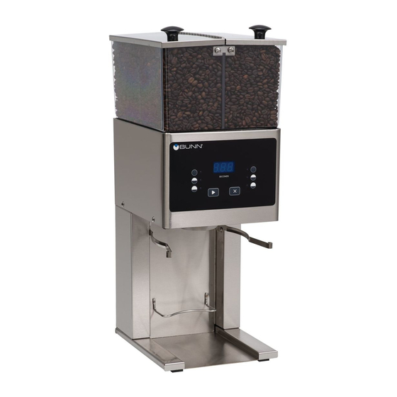
GRINDERS
Includes: MHG, FPG,
FPG-2, LPG-2, G1, G2, G3,
G2 trifecta™, G9, G9WD,
G9-2 & G9-2T DBC
SERVICE & REPAIR MANUAL
BUNN-O-MATIC CORPORATION
POST OFFICE BOX 3227
SPRINGFIELD, ILLINOIS 62708-3227
PHONE: (217) 529-6601
FAX: (217) 529-6644
To ensure you have the latest revision of the Operating Manual, or to view the Illustrated Parts
Catalog, Programming Manual, or Service Manual, please visit the Bunn-O-Matic website, at
www.bunn.com. This is absolutely FREE, and the quickest way to obtain the latest catalog and
manual updates. For Technical Service, contact Bunn-O-Matic Corporation at 1-800-286-6070.
41545.0000C 11/11 ©2009 Bunn-O-Matic Corporation
Advertisement
Table of Contents

Related Manuals for Bunn MHG


Summary of Contents for Bunn MHG
- Page 1 To ensure you have the latest revision of the Operating Manual, or to view the Illustrated Parts Catalog, Programming Manual, or Service Manual, please visit the Bunn-O-Matic website, at www.bunn.com. This is absolutely FREE, and the quickest way to obtain the latest catalog and manual updates. For Technical Service, contact Bunn-O-Matic Corporation at 1-800-286-6070.
- Page 2 SOLE OPTION AS SPECIFIED HEREIN, TO REPAIR, REPLACEMENT OR REFUND. In no event shall BUNN be liable for any other damage or loss, including, but not limited to, lost profits, lost sales, loss of use of equipment, claims of Buyer’s customers, cost of capital, cost of down time, cost of substitute equipment, facilities or services, or any other special, incidental or consequential damages.
-
Page 3: Table Of Contents
CONTENTS Warranty and Trademark ....................3 Introduction ........................4 Recommended Daily Cleaning ..................4 G9WD Packaging & Shim Removal ................5 Operating Controls ......................6 Troubleshooting ......................10 Service ..........................14 Component Access ...................14 Bag Sensor .......................15 Motor and Grind Chamber ................16 Capacitor ......................30 Circuit Breaker ....................31 Hopper Selector Switch ..................32 Off/On/Start Switch ...................34 Urn/Carafe Selector Switch ................35... -
Page 4: Introduction
The use of a damp cloth rinsed in any mild, nonabrasive, liquid detergent is recommended for cleaning all surfaces on Bunn-O-Matic equipment. Care should be taken not to scratch the hopper or windows with any abrasive material. Regular cleaning will keep your grinder looking new for years. Refer to the Installation &... -
Page 5: G9Wd Packaging & Shim Removal
G9 WD - Packaging & Shim Removal WARNING MUST BE COMPLETED BY AUTHORIZED SERVICE PERSONNEL. DO NOT PLUG IN ! SEE INSTRUCTIONS BELOW BEFORE USING ! Step 1 - Remove & discard tape holding funnel arm in place. (Figure 1) Step 2 - Remove &... -
Page 6: Operating Controls
OPERATING CONTROLS Model G9WD Grind Pad (a) Pressing initiates a grind cycle. Stop Pad (b) Pressing ends the operation of the grinder. ® Pad (c) Pressing the copyright pad allows programming access. Pads (d) “Hidden” buttons used to navigate setup and programming menus. Pads (e) Press button to select small, medium or large batch size. - Page 7 OPERATING CONTROLS (Continued) Model G9 Off/On/Start Switch OFF - (left position) Placing the switch in this position stops the operation of the grinder. ON - (center, resting position) The switch will return to this position after a grind cycle has begun and will remain in this position after grinding has ceased.
- Page 8 OPERATING CONTROLS (Continued) Model MHG Grind Pad (a) Pressing initiates a timed grind cycle. Stop Pad (b) Pressing ends the operation of the grinder. ® PAD (c) Pressing the ® pad allows programming access. Hopper/Batch Selector Pads (d) These pads are located on the funnel depictions on each side of the grinder with a total of 6 pads. Selecting one of these pads will select the amount of grind and side from which to grind.
- Page 9 OPERATING CONTROLS (Continued) Model FPG Off/On/Start Switch OFF - (upper position) Switching to this position stops all operation of the grinder. ON - (middle position) The switch will return to this position after a grind cycle has begun and will remain in this position after grinding has ceased. START - (lower, momentary position) Pressing the switch to this position P2947 and releasing initiates a grind cycle.
-
Page 10: Troubleshooting
TROUBLESHOOTING A troubleshooting guide is provided to suggest probable causes and remedies for the most likely problems encountered. If the problem remains after exhausting the troubleshooting steps, contact the Bunn-O-Matic Technical Service Department. • Inspection, testing, and repair of electrical equipment should be performed only by qualified service personnel. - Page 11 TROUBLESHOOTING (cont.) Probable Cause Problem Remedy Grinder will not start. (Continued) 5. Motor Each motor is equipped with a temperature and current overload protection feature which will im- mediately shut off the motor when an overload has occurred. Check the grinder for obstructions. Refer to Service - Motor for testing pro- cedures.
- Page 12 Problem Probable Cause Remedy Grinder starts, but will not dispense 1. Hopper(s) Begin each grind cycle by visually from hopper. inspecting the hopper(s) for ample supplies of whole bean coffee. 2. Blockage of hopper(s) Foreign materials must not block the openings at the bottom of the hopper(s).
- Page 13 TROUBLESHOOTING (cont.) PROBABLE CAUSE PROBLEM REMEDY Incorrect coffee grind dispensed. 1. Burr adjustment Refer to the Adjustment section in the Installation and Operation Manual. Excessive chaff 1. Dechaffer Replace the dechaffer springs. Replacement dechaffer springs are provided in the literature package accompnting the grinder.
-
Page 14: Service
SERVICE This section provides procedures for testing and replacing various major components used in this grinder should service become necessary. Refer to Troubleshooting for assistance in determining the cause of any problem. WARNING - Inspection, testing, and repair of electri- cal equipment should be performed only by qualified service personnel. -
Page 15: Bag Sensor
SERVICE (Cont.) BAG SENSOR SWITCH (Models G1, G2, G3) or CUP SENSOR SWITCH (MODEL G2 TRIFECTA) Disconnect the grinder from the power source. If voltage is present as described, proceed to If voltage is not present as described, refer to the Wiring Diagrams and check the grinder wiring harness. -
Page 16: Motor And Grind Chamber
SERVICE (Cont.) Check the voltage across the white, red or red/ AC MOTOR AND GRIND CHAMBER black and white/blue wires on terminals L1 & L2 with a voltmeter. Connect the grinder to the power source. When the Off/On/Start switch is momen- tarily placed in the “START”... - Page 17 SERVICE (Cont.) AC MOTOR AND GRIND CHAMBER (cont.) 19. Install burr rotor cup (5). 11. Clean all grinding burrs and mounting surfaces 20. Install grind selector dial plate and grind selector before reassembly. knob assembly on the grind chamber housing and 12.
- Page 18 SERVICE (Cont.) AC MOTOR AND GRIND CHAMBER (cont.) 18 1 19 17 20 7 6 4 11 10 9 8 P1708 FIG. 5 GRIND CHAMBER COMPONENTS 9. Remove bushing (10) and shaft extension (11) from Removal and Replacement - Grind Chamber - Fig. 5: grinder motor shaft.
- Page 19 SERVICE (Cont.) DC MOTOR AND GRIND CHAMBER - G1MD ONLY Check the voltage across the (+) and (-) terminals with a voltmeter. Connect the grinder to the power source. When the Off/On/Start switch is momen- tarily placed in the “START” (lower) position and then left in the “ON”...
- Page 20 SERVICE (Cont.) DC MOTOR AND GRIND CHAMBER - G1MD ONLY BLU to BLU from Rectifier (cont.) BLU to WHI/BLU from Relay (3) 10. Remove motor and bracket out the rear of the RED to Rectifier (-) grinder housing. BLK to Rectifier (+) 11.
- Page 21 SERVICE (Cont.) 14. Install the adjusting screw w/bearing (19) into the DC MOTOR AND GRIND CHAMBER - G1MD ONLY grind selector dial plate (18). (cont.) 15. Install grind selector dial plate (18) with adjust- 11. Install burr (7) on burr auger rotor/spring assem- ing screw w/bearing (19) onto the grind chamber bly (6) securing with two .250”-20 screws (5).
- Page 22 SERVICE (Cont.) MOTOR (Models LPG & FPG) Removal and Replacement: 1. On Model LPG-2E, disconnect the black wire and the white wire to the motor from the main wiring harness, the red wire to the circuit breaker and the red wire to the Off/On/Start switch. On Model LPG disconnect the motor wiring harness from the main wiring harness.
- Page 23 SERVICE (Cont.) MOTOR (Models LPG & FPG) 8. Remove spacer plate (3) and set aside for reas- sembly. 9. Lift solenoid bracket and solenoids (4) over the motor and burr housing assembly (6) and set aside for reassembly. 10. Remove the #8-32 setscrew (5) and set aside for reassembly.
- Page 24 SERVICE (Cont.) MOTOR (Models LPG & FPG) MODEL LPG ONLY 10 11 13 14 15 16 P1051 FIG. 12 ROTOR/AUGER, BURRS AND MOTOR COVER 20. Remove the two #8-32 flat head screws securing NOTE: Steps 30 thru 33 apply only to Model LPG-2E. the motor cover (18) to the motor and housing 30.
- Page 25 SERVICE (Cont.) DECHAFFER (Models LPG & FPG) 3 2 1 P1062 FIG. 13 DECHAFFER Location: OPTONAL EXTRA The dechaffer spring plates are located in the burr FINE DECHAFFER housing cap. P1063 FIG. 14 DECHAFFER REMOVAL/REPLACEMENT Removal and Replacement: Refer to Fig. 14 1.
- Page 26 SERVICE (Cont.) The entire wiring harness must be fed into the bottom of the grinder housing through the hole in the motor MOTOR (Models G9, G9-2, MHG) mounting plate. Remove both 6-32 screws beneath the upper front inspection panel. Remove the six 10-32, hex head screws on top of the motor mounting plate.
- Page 27 SERVICE (Cont.) MOTOR (Models G9, G9-2, MHG) 6 7 8 P1311 FIG. 17 MOTOR AND GRIND CHAMBER 6. Rotor 1. Indicator Adjustment Cap & Decal 7. Spring 2. Adjusting Screw 8. Burr (Rotating) 3. Burr Housing Cap 9. Burr (Stationary) 4.
- Page 28 SERVICE (Cont.) SNUBBER (Models G9, G9-2, MHG) WHI/ BLU to Snubber WHI/BLU to Relay WHI/BLK to Cordset (120V models) RED/BLK to Cordset (230V models) F IN F IN WHI/BLK to Snubber P611 GRN to Chasis Ground FIG. 18 SNUBBER YEL to Snubber FRANKLIN MOTOR Location: The snubber is located at the back of the motor...
- Page 29 SERVICE (Cont.) Grinder Scale (Model G9WD only) CALIBRATION 1. Place empty funnel into funnel rails. 2. Press and hold the right hidden (copyright) button until the “MACHINE TYPE” menu appears. (See level 2 programming) 3. Press the middle button under the screen until the “CALIBRATE SCALES?” menu appears. 4.
-
Page 30: Capacitor
SERVICE (Cont.) Capacitor (Model LPG only) Removal and Replacement: 1. Disconnect the capacitor wiring harness from the main wiring harness. 2. Remove the #8-32 nut attaching the capacitor and mounting bracket to the hopper housing and remove the bracket, shield, capacitor and capacitor wiring harness as an assembly. -
Page 31: Circuit Breaker
SERVICE (Cont.) Circuit Breaker (Models LPG, LPG-2E, FPG, FPG-2 DBC) Removal and Replacement: 1. Remove the wires from the circuit breaker. 2. Remove the face nut securing circuit breaker to the motor support. 3. Remove circuit breaker. 4. Install new circuit breaker in motor support and secure with face nut. -
Page 32: Hopper Selector Switch
SERVICE (Cont.) Hopper Selector Switch (Model LPG-2E only) 6. Place the selector switch in the right position. 7. Check for continuity across the terminals on the rear of the switch. Continuity should not be present across terminals in the right position. If continuity is not present as described, reconnect the wires, the switch is operating properly. - Page 33 SERVICE (Cont.) Hopper Selector Switch (Model G9-2 only) Removal and Replacement: 1. Remove all wires from the switch terminals. 2. Compress the clips inside the front of the housing and gently push the switch through the opening. 3. Push the new switch into the opening and spread the clips to retain the switch in the housing.
-
Page 34: Off/On/Start Switch
SERVICE (Cont.) Off/On/Start Switch (Models LPG, LPG-2E, FPG, G-1,G-2,G-3, G9, G9-2, G2 trifecta) 6. Check for continuity across the right terminals when the switch is placed in the “START” (lower) position only. Continuity must not be present in the “OFF” position. If continuity is present as described, the Off/On/Start switch is operating properly. -
Page 35: Urn/Carafe Selector Switch
SERVICE (Cont.) Urn/Carafe Switch (Models G9, G9-2) 4. Place the switch in the “URN” position; check for continuity across the orange and green wire ter- minals. If continuity is present as described, the switch is operating properly. If continuity is not present as described, replace CARAFE the switch. -
Page 36: Batch Selector Switch
SERVICE (Cont.) Batch Selector Switch (Model FPG) If continuity is present at all positions, the switch is operating properly. If continuity is not present at any position, replace the switch. 9. Refer to the Fig. 33 when reconnecting wires. Removal and Replacement: 1. -
Page 37: Potentiometer
SERVICE (Cont.) Potentiometer (Model FPG) If continuity is present at all positions, the potentiometer SMALL MEDIUM LARGE switches are operating properly. If continuity is not present at any position, replace the potentiometer switches. 8. Refer to Fig 35 when reconnecting wires. Removal and Replacement: 1. -
Page 38: Rectifier
SERVICE (Cont.) Rectifier (Models G1 MD, FPG-2 DBC) Removal and Replacement: Disconnect the wires from the rectifier. Remove the #10-32 screw securing the rectifier to the motor mounting bracket. Remove the rectifier and discard. Install new rectifier on the rear of the motor mount- ing bracket and secure with a #10-32 screw. -
Page 39: Relay
SERVICE (Cont.) Relay (Early Model G-9) Remove the white/red and white/blue wires from the relay contacts. Check for continuity across the relay contacts when the Off/On/Start switch is placed in the “START” (right) position and released. Connect grinder to the power supply. Continuity must be present for the approximate setting on the timer. - Page 40 SERVICE (Cont.) Check the voltage across the white wire or red/ black on terminal B and either white/red wire with Relay (Models G1, G2, G3, G2 trifecta) a voltmeter. Place the Off/On/Start in either the “ON” (center) position or “START” (lower) posi- tion.
- Page 41 SERVICE (Cont.) RELAY (cont.) Removal and Replacement (120 Volt and 240V 60 Hz Removal and Replacement (230 volt 50 Hz Models): Models): 1. Remove the wires from the relay terminals. 1. Remove the wires from the relay terminals. 2. Remove the two #6-32 screws securing the relay 2.
- Page 42 SERVICE (Cont.) Relay (Models MHG, FPG-2 DBC, Late Model G-9, G9-2, G9-2 DBC) Removal and Replacement 1. Disconnect the grinder from the power supply. 2. Remove all wires from the relay terminals. 3. Remove the two 8-32 screws attaching the relay to the mounting bracket.
-
Page 43: Hopper Slide Plates
SERVICE (Cont.) Hopper Slide Plates (Models G9-2, G9-2 DBC) A. Solenoid Coil B. Fiber Washer C. Spring D. Spring Retaining Washer E. Solenoid Plunger Snap Ring G. Short Link H. Long Link Slide Plate J. Pivot Pin K. Stop Block L. - Page 44 SERVICE (Cont.) Hopper Slide Plates (Models MHG) A. Solenoid Coil B. Slide Gate C. Slide Gate Support D. Collector E. Collector Seal Solenoid Mounting Plate Removal and Replacement: 1. Remove the hopper from the grinder. FIG 45 HOPPER SLIDE PLATES 2.
-
Page 45: Solenoid
SERVICE (Cont.) Solenoids (Models MHG, FPG-2 DBC, LPG-2, G9-2, G9-2 DBC) If continuity is present as described, reconnect the wires, and proceed to #7. If continuity is not present as described, replace the limit thermostat. 7. Check the solenoid for coil action when the control switch is momentarily pressed to the “START”... -
Page 46: Timer
SERVICE (Cont.) Timer (Model LPG-2E) If voltage is present as described, proceed to step If voltage is not present as described, replace the timer. 7. Place the hopper selector switch in the right posi- tion. 8. Insert the leads of a voltmeter set to read at least 120 volts AC, along side the red wire (terminal 8) and the violet wire (terminal 9) of the harness plug. - Page 47 SERVICE (Cont.) Timer (Model LPG-2E) 5. Remove timer and timer mounting bracket from Test Procedure: the grinder. 1. Disconnect grinder from the power source. 6. Remove the four #6-32 keps nuts securing the timer 2. Insert the leads of a voltmeter set to read at least to the mounting bracket.
- Page 48 SERVICE (Cont.) Timer (Model G9) Check the voltage across terminals TL1 and TL4 with a voltmeter when the Off/On/Start switch is placed in the “START” (right) position and released. Connect grinder to the power supply. The indication must be: (a) 120 volts ac for two wire 120 volt models. (b) 240 volts ac for two wire 240 volt models.
- Page 49 SERVICE (Cont.) Timer (Model G9-2) 6. Connect a voltmeter across contacts 3 & 7 of the larger connector (P4) on the timer board. Plug-in the grinder. Momentarily press the Off/On/Start switch to “START” (lower) position and release. The indication must be 120 volts ac for 120V models d s) E (S D IS...
-
Page 50: Control Board
SERVICE (Cont.) Control Board (Model MHG) Removal and Replacement Disconnect the grinder from the power supply. Remove the front access panel. Remove all wires from the control board termi- nals. Remove the bracket and control board by remov- ing the two 8-32 screws securing the bracket to the grinder base. - Page 51 SERVICE (Cont.) Control Board (Models FPG-2 & G9-2 DBC) Removal and Replacement Disconnect the grinder from the power supply. Remove the rear access panel. Disconnect all harness plugs from the control board. Remove the two knurled nuts from the bottom of the control board and remove the control board.
-
Page 52: Membrane Switch
SERVICE (Cont.) Membrane Switches (Model MHG only) Removal and Replacement 1. Disconnect the grinder from the power supply. 2. Remove the rear access panel. 3. Disconnect the membrane switch harness from the control board. 4. Carefully peel the membrane switch from the front of the switch bezel. - Page 53 SERVICE (Cont.) Membrane Switches (Models FPG-2 & G9-2 DBC) Removal and Replacement 1. Disconnect the grinder from the power supply. 2. Remove the rear access panel. 3. Disconnect the membrane switch harness from the control board. 4. Carefully peel the membrane switch from the front of the switch bezel.
-
Page 54: Emi Filter
SERVICE (Cont.) EMI Filter (Models FPG & FPG-2) Removal and Replacement: 1. Disconnect the wires from the EMI Filter. 2. Remove the two screws securing the EMI Filter. 3. Remove and discard EMI Filter. 4. Install new EMI Filter using two screws to secure EMI Filter to its former location. -
Page 55: Funnel Sensing Coil
SERVICE (Cont.) Funnel Sensing Coil (Models MHG & G9-2 DBC) Removal and Replacement 1. Disconnect the grinder from the power supply. 2. Remove the two 6-32 screws attaching the coil cover to the grinder housing. 3. Pull slightly away from the housing and disconnect the two wires from the coil. -
Page 56: Memory Clock Board
SERVICE (Cont.) Memory Clock Board (Model MHG) Removal and Replacement 1. Disconnect the grinder from the power supply. 2. Remove the front access panel. 3. Remove the two 8-32 screws securing the compo- nent bracket to the grinder base and tilt forward to gain access to the memory clock board. -
Page 57: Display Board
SERVICE (Cont.) Display Board (Model MHG) Removal and Replacement 1. Disconnect the grinder from the power supply. 2. Remove the two 6-32 screws attaching the mem- brane switch bezel to the hopper housing. 3. Tilt the bezel assembly forward. 4. Remove the four 8-32 screws attaching the board cover bracket to the switch bezel and remove the bracket. -
Page 58: Wiring Schematics
TRIAC MAP for MHG MOV1 controls Transformer @ J5-4,5,6 TH1 & MOV2 controls Left Gate @ J5-3 TH2 & MOV3 controls Relay @ J5-2 TH3 & MOV4 controls Right Gate @ J5-1 41545 122209... - Page 59 TRIAC MAP for FPG-2 DBC and G9-2 DBC TH1 & MOV1 controls Left Gate @ J1-1 TH2 & MOV2 controls Relay @ J1-2 TH3 & MOV3 controls Right Gate @ J1-3 MOV4 controls Transformer @ J1-4,5,6 41545 122209...
-
Page 60: Wiring Diagrams
Small Batch Size "Left" Large Batch Size "Right" SWITCH UNIT ASSY Medium Batch Size "Right" Small Batch Size "Right" GRINDER MOTOR WHI/BLU 120 OR 230 VOLTS AC 2 WIRE RELAY CONTACTS SINGLE PHASE 50/60 HZ 33734.0000G 02/05 © 2001 Bunn-O-Matic Corporation 41545 122209... -
Page 61: Single Phase
Grind Stop Hidden Button “Right” Hot Coffee “Full” Hot Coffee “Half” Iced Coffee SWITCH UNIT ASSY GRINDER MOTOR WHI/BLU 120 OR 230 VOLTS AC 2 WIRE RELAY CONTACTS SINGLE PHASE 50/60 HZ 33734.0003A 02/05 © 2005 Bunn-O-Matic Corporation 41545 122209... - Page 62 Small Batch Size "Left" Large Batch Size "Right" SWITCH UNIT ASSY Medium Batch Size "Right" Small Batch Size "Right" GRINDER MOTOR WHI/BLU 100 VOLTS AC 2 WIRE RELAY CONTACTS SINGLE PHASE 50 HZ 33734.0004A 03/05 © 2005 Bunn-O-Matic Corporation 41545 122209...
- Page 63 "Digital" Left Hidden Button STATIC SHIELD "Brewer" Center Hidden Button "Control" Right Hidden Button 100 VOLTS AC, 120 VOLTS AC, 240 VOLTS AC 2 WIRE SINGLE PHASE 50/60 HZ SWITCH UNIT ASSY 36399.0000D 08/05 © 2003 Bunn-O-Matic Corporation 41545 122209...
- Page 64 SHIELD WHT/BLU SWITCH UNIT ASSY 100 VOLTS AC, 120 VOLTS AC, 240 VOLTS AC 2 WIRE + Gnd SINGLE PHASE, 50/60HZ 45151.0000A 11/11 ©2011 BUNN-O-MATIC CORPORATION White Strip-Tac Plus Black Ink Finished Size: 4.0" x 4.25" 50% Reduction 41545 111711...
- Page 65 SWITCH TIMER ASSY. GRINDER (Hopper Slide Gate Timer WHI/BLK Dial Wiring) Right - Brown Left - Orange OFF/ON/START SLIDE GATES SWITCH 100 VOLTS AC 27103.0000D 04/07 ©1996 120 VOLTS AC BUNN-O-MATIC CORPORATION 2 WIRE SINGLE PHASE 60 HZ 41545 122209...
- Page 66 WIRING DIAGRAMS 41545 122209...
- Page 67 WIRING DIAGRAMS SCHEMATIC WIRING DIAGRAM LPG & LPG2 GREEN WHI/BLK WHI/BLK WHI/BLU WHI/BLU TIMER WHI/BRN WHI/BRN WHI/BRN WHI/BRN WHI/BLU WHI/BLU MOTOR 10529.0000C 3/92 © 1990 120 VOLTS AC BUNN-O-MATIC CORPORATION 2 WIRE SINGLE PHASE 60 HZ 41545 122209...
- Page 68 WIRING DIAGRAMS SCHEMATIC WIRING DIAGRAM LPG-A GRN/YEL WHI/BLK WHI/BLK WHI/BLU WHI/BLU TIMER WHI/BRN WHI/BRN WHI/BRN WHI/BRN WHI/BLU WHI/BLU MOTOR 10529.0002E 8/01 © 1990 230 VOLTS AC BUNN-O-MATIC CORPORATION 2 WIRE SINGLE PHASE 50/60 HZ 41545 122209...
- Page 69 WIRING DIAGRAMS SCHEMATIC WIRING DIAGRAM LPG W/Capacitor GREEN WHI/BLK WHI/BLK WHI/BLU WHI/BLU TIMER WHI/BRN WHI/BRN WHI/BRN WHI/BRN WHI/BRN WHI/BRN WHI/BLU WHI/BLU MOTOR 120 VOLTS AC 2 WIRE 10529.0003E 10/98 © 1998 BUNN-O-MATIC CORPORATION SINGLE PHASE 60 HZ 41545 122209...
- Page 70 WIRING DIAGRAMS SCHEMATIC WIRING DIAGRAM LPG-B GREEN WHI/BLK WHI/BLK WHI/BLU WHI/BLU TIMER WHI/BRN WHI/BRN WHI/BRN WHI/BRN WHI/BLU WHI/BLU MOTOR 100 VOLTS AC 10529.0001D 10/98 © 1990 2 WIRE BUNN-O-MATIC CORPORATION SINGLE PHASE 50-60 HZ 41545 122209...
- Page 71 2 WIRE + GRD K-8 or K-9 SINGLE PHASE 50/60 HZ WHI/ORA RED/BLK WHI/VIO 1 or A 0 or B 10190.0000H 05/10 © 1985 BUNN-O-MATIC CORPORATION White Strip-Tac Plus Black Ink Finished Size: 6" x 3" ~100% Reduction 41545 072710...
- Page 72 WHI/RED WHI/BLU WHI/YEL WHI/GRN K1 N.O. WHI/ORA TIMER OPTIONAL KEY SW 120 VOLTS AC 2 WIRE SINGLE PHASE 60 HZ 10173-0000F 4/91 © 1987 BUNN-O-MATIC CORPORATION SCHEMATIC WIRING DIAGRAM G9-URN/CARAFE GREEN WHI/RED WHI/RED WHI/RED WHI/BLU WHI/YEL WHI/ORA WHI/GRN K1 N.O.
- Page 73 MEDIUM BATCH SIZE "LEFT" SMALL BATCH SIZE "LEFT" "DIGITAL' LEFT HIDDEN BUTTON "BREWER" CENTER HIDDEN "CONTROL" RIGHT HIDDEN 120 VOLTS AC 2 WIRE SINGLE PHASE 60 HZ 41449.0000A 11/09 © 2009 BUNN-O-MATIC CORPORATION 41545 072710 White Strip-Tac Plus Black Ink...
- Page 74 K1 N.O. WHI/ORA OPTIONAL KEY SW TIMER 120 VOLTS AC 2 WIRE SINGLE PHASE 60 HZ OPTIONAL OPTIONAL BREWER 10388-0000B 12/88 © 1988 BUNN-O-MATIC CORPORATION MULTI-SET SW INTERFACE CONNECTOR SCHEMATIC WIRING DIAGRAM G9 GREEN WHI/RED WHI/RED WHI/RED WHI/BLU WHI/YEL WHI/ORA WHI/GRN K1 N.O.
- Page 75 WHI/GRN WHI/ORA WHI/BLK WHI/YEL WHI/BLK HOPPER SELECTOR SW WHI/RED OPTIONAL GRINDER INTERFACE MULTI-SET SW CONNECTOR WHI/BLU SNUBBER 230 VOLTS AC WHI/BLK 2 WIRE WHI/RED WHI/BLU RED/BLK SINGLE PHASE K1 N.O. 50 HZ 10768.0000E 05/03 © 1993 BUNN-O-MATIC CORPORATION 41545 122209...
- Page 76 WIRING DIAGRAMS 41545 122209...
- Page 77 WHI/BLU TIMER WHI/BRN WHI/BRN WHI/BRN WHI/BRN WHI/BLU WHI/BLU MOTOR 120 VOLTS AC 36781.0000A 04/04 ©2004 BUNN-O-MATIC CORPORATION 2 WIRE SINGLE PHASE 60 HZ SCHEMATIC WIRING DIAGRAM FPGA GREEN White Strip-Tac Plus Black Ink Finished Size: 4.5" x 5.0" WHI/BLK ?0% Reduction SELECT SW.
- Page 78 Medium Batch Size "Right" Small Batch Size "Right" RECT 100 VOLTS AC – 120 VOLTS AC 2 WIRE SINGLE PHASE WHI/BLK 60 HZ 36706.0000B 04/07 © 2004 Bunn-O-Matic Corporation White Strip-Tac Plus Black Ink Finished Size: 3.5" x "4.25 55≈% Reduction 41545 122209...
- Page 79 Small Batch Size "Left" Large Batch Size "Right" Medium Batch Size "Right" Small Batch Size "Right" 230 VOLTS AC 2 WIRE SWITCH UNIT ASSY SINGLE PHASE 50 HZ 36706.0001B 04/06 © 2005 Bunn-O-Matic Corporation NOT A PURCHASED SCHEMATIC FOR REFERENCE ONLY 41545 122209...
Need help?
Do you have a question about the MHG and is the answer not in the manual?
Questions and answers