Bryant 549B Installation, Start-Up And Service Instructions Manual
Durapac plus series sizes 036-072 3 to 6 tons single package rooftop high-efficiency heat pump units
Hide thumbs
Also See for 549B:
- Installation, start-up and service instructions manual (48 pages) ,
- User manual (170 pages) ,
- User manual (122 pages)
Table of Contents
Advertisement
Quick Links
Download this manual
See also:
User Manual
IMPORTANT — READ BEFORE INSTALLING
1. Read and become familiar with these installation
instructions before installing this unit. (See Fig. 1.)
2. Be sure the installation conforms to all applicable
local and national codes.
3. These instructions contain important information for
the proper maintenance and repair of this equipment.
Retain these instructions for future use.
CONTENTS
SAFETY CONSIDERATIONS . . . . . . . . . . . . . . . . . . . . . . . . . . . . . . . . 1
INSTALLATION. . . . . . . . . . . . . . . . . . . . . . . . . . . . . . . . . . . . . . . . 1-21
I. Locate the Unit. . . . . . . . . . . . . . . . . . . . . . . . . . . . . . . . . . . 3
II. Unit Duct Connections . . . . . . . . . . . . . . . . . . . . . . . . . . . . 3
III. Rig and Place Unit . . . . . . . . . . . . . . . . . . . . . . . . . . . . . . . . 3
IV. Field Connections . . . . . . . . . . . . . . . . . . . . . . . . . . . . . . . . . 5
V. Electrical Connections . . . . . . . . . . . . . . . . . . . . . . . . . . . . . 7
VI. Accessory Installation . . . . . . . . . . . . . . . . . . . . . . . . . . . . 14
Pre-Start-Up . . . . . . . . . . . . . . . . . . . . . . . . . . . . . . . . . . . . . . . . . 21
START-UP . . . . . . . . . . . . . . . . . . . . . . . . . . . . . . . . . . . . . . . . . . . 21-38
I. Compressor Rotation . . . . . . . . . . . . . . . . . . . . . . . . . . . . . 21
II. Heating Section Start-Up and Adjustments . . . . . . . . . . 21
III. Cooling Section Start-Up and Adjustments . . . . . . . . . . . 22
IV. Indoor Airflow and Airflow Adjustments . . . . . . . . . . . . . . 24
Care And Maintenance . . . . . . . . . . . . . . . . . . . . . . . . . . . . . . . 38
I. Air Filter . . . . . . . . . . . . . . . . . . . . . . . . . . . . . . . . . . . . . . . . 38
Service. . . . . . . . . . . . . . . . . . . . . . . . . . . . . . . . . . . . . . . . . . . . 38-41
I. Cleaning . . . . . . . . . . . . . . . . . . . . . . . . . . . . . . . . . . . . . . . . 38
II. Lubrication . . . . . . . . . . . . . . . . . . . . . . . . . . . . . . . . . . . . . . 39
III. Blower Belt Adjustment . . . . . . . . . . . . . . . . . . . . . . . . . . . 39
IV. Outdoor Fan Adjustment . . . . . . . . . . . . . . . . . . . . . . . . . . 39
V. Economizer Adjustment . . . . . . . . . . . . . . . . . . . . . . . . . . . 39
VI. Current Lockout Relay (CLO) . . . . . . . . . . . . . . . . . . . . . . . 40
VII. High-Pressure Switch . . . . . . . . . . . . . . . . . . . . . . . . . . . . . 40
VIII. Loss-of-Charge Switch . . . . . . . . . . . . . . . . . . . . . . . . . . . . 40
IX. Freeze-Stat . . . . . . . . . . . . . . . . . . . . . . . . . . . . . . . . . . . . . . 40
X. Refrigerant Charge . . . . . . . . . . . . . . . . . . . . . . . . . . . . . . . 40
XI. Replacement Parts . . . . . . . . . . . . . . . . . . . . . . . . . . . . . . . 40
Troubleshooting . . . . . . . . . . . . . . . . . . . . . . . . . . . . . . . . . 42-46
Start-Up Checklist . . . . . . . . . . . . . . . . . . . . . . . . . . . . . . . . . CL-1
SAFETY CONSIDERATIONS
Recognize safety information. This is the safety-alert symbol
(
). When you see this symbol on the unit and in instruc-
tions or manuals, be alert to the potential for personal injury.
Understand the signal words — DANGER, WARNING, and
CAUTION. These words are used with the safety-alert sym-
bol. Danger identifies the most serious hazards which will
result in severe personal injury or death. Warning indicates
a condition that could result in personal injury. Caution is
used to identify unsafe practices which would result in minor
personal injury or product and property damage.
installation, start-up and
service instructions
SINGLE PACKAGE ROOFTOP
HIGH-EFFICIENCY HEAT PUMP UNITS
Cancels: II 549B-36-1
Page
WARNING: Before performing service or mainte-
nance operations on unit, turn off main power switch
to unit. Electrical shock could cause personal injury.
1. The power supply (volts, hertz, and phase) must cor-
respond to that specified on unit rating plate.
2. The electrical supply provided by the utility must be
sufficient to handle load imposed by this unit.
3. Refer to Locate the Unit section on page 3 and Fig. 2
for locations of electrical inlets, condensate drain,
duct connections, and required clearances before set-
ting unit in place.
4. This installation must conform with local building
codes and with NEC (National Electrical Code) or
NFPA (National Fire Protection Association) 54 TIA-
54-84-1. Refer to Provincial and local plumbing or
wastewater codes and other applicable local codes.
5. Approved for outdoor installation on wood flooring or
on class A, B, or C roof covering materials.
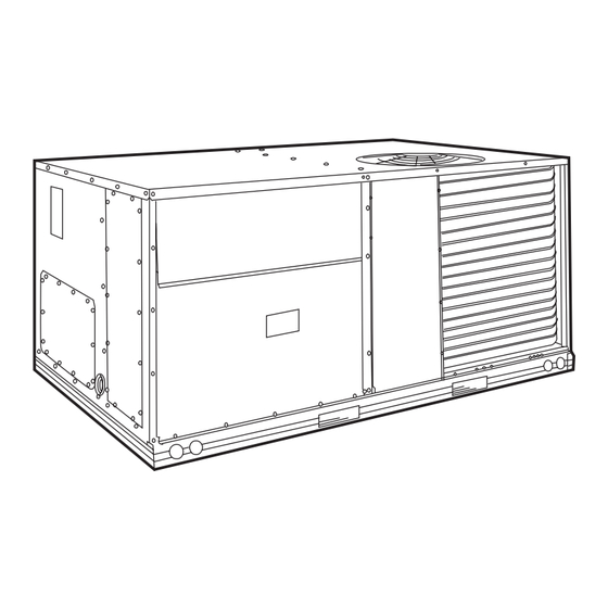
Unit is shipped in the vertical airflow configuration (see
Fig. 1). To convert to horizontal discharge, remove horizontal
duct opening covers. Using the same screws, install covers on
duct openings in basepan of unit with the insulation side
down. Seals around duct openings must be tight.
All units can be connected into existing duct systems that are
properly sized and designed to handle an airflow of 300 to
500 cfm per each 12,000 Btuh of rated cooling capacity.
NOTE: When installing any accessory item, see the manufac-
turer's installation instructions packaged with the accessory.
A qualified installer or agency must use only factory-
authorized kits or accessories when modifying this unit.
DuraPac Plus Series
Sizes 036-072
3 to 6 Tons
II 549B-36-2
Fig. 1 — Typical Unit
INSTALLATION
549B
2/15/01
Advertisement
Table of Contents
Troubleshooting

Related Manuals for Bryant 549B


Summary of Contents for Bryant 549B
- Page 1 installation, start-up and 549B service instructions DuraPac Plus Series SINGLE PACKAGE ROOFTOP Sizes 036-072 3 to 6 Tons HIGH-EFFICIENCY HEAT PUMP UNITS Cancels: II 549B-36-1 II 549B-36-2 2/15/01 IMPORTANT — READ BEFORE INSTALLING 1. Read and become familiar with these installation instructions before installing this unit.
- Page 2 — —...
-
Page 3: I. Locate The Unit
I. LOCATE THE UNIT curb as shown in Fig. 4. Improperly applied gasket can also result in air leaks and poor unit performance. A. Clearance Curb should be level. Unit leveling tolerances are shown in Maintain clearance around and above unit to provide mini- Fig. - Page 4 CONNECTOR D ALT POWER CONTROL PKG. ACCY. DRAIN HOLE ″ [19] NPT ″ CRBTMPWR001A00 ″ [31.7] NPT [19] NPT CRBTMPWR002A00 ″ ″ ″ ″ 1′-9 1′-4″ ″ [19] NPT CRBTMPWR003A00 [551] [406] [44.5] [12.7] NPT [12.7] NPT ″ ″ [31.7] NPT CRBTMPWR004A00 [19] NPT NOTES:...
-
Page 5: Iv. Field Connections
MAXIMUM ALLOWABLE DIFFERENCE (in.) Fig. 5 — Unit Leveling Tolerances NOTES: DIMENSIONS OPERATING 1. Dimension in ( ) is in millimeters. UNIT WEIGHT ‘‘A’’ ‘‘B’’ ‘‘C’’ 2. Hook rigging shackles through holes in base rail, as shown in detail 549B ‘‘A.’’... - Page 6 Table 1 — Physical Data UNIT SIZE 549B NOMINAL CAPACITY (tons) OPERATING WEIGHT (lb) Unit Durablade Economizer EconoMi$er Roof Curb COMPRESSOR Scroll Quantity Oil (oz) REFRIGERANT TYPE R-22 Operating Charge (lb) 10.8 11.9 OUTDOOR FAN Propeller Type Quantity...Diameter (in.) 1...22 1...22 1...22 1...22...
-
Page 7: V. Electrical Connections
5.0” 18.5” CAUTION: DO NOT DRILL OR INSERT SCREWS IN SHADED AREA NAMEPLATE SUPPLY RETURN DRAIN PLUG NOTE: Drain plug is shown in factory-installed position. Fig. 7 — Condensate Drain Connection (Side View) INLET/OUTLET PANEL Fig. 8 — Location of Coil Area Not to be Drilled 4. - Page 8 460-3-60 (Sizes 036 and 048) 208/230-3-60 460-3-60 (Sizes 060 and 072) 208/230-3-60 (Sizes 036 and 048) 208/230-1-60 LEGEND — Contactor COMP — Compressor — Indoor Fan Contactor — National Electrical Code Fig. 9 — Power Wiring Connections — —...
- Page 9 Table 2A — Electrical Data — Standard Motor (Units Without Electrical Convenience Outlet) MINIMUM UNIT VOLTAGE ELECTRIC POWER NOMINAL COMPRESSOR DISCONNECT UNIT RANGE HEAT* SUPPLY VOLTAGE SIZE 549B V-PH-Hz kW† MOCP —/— —/— 25.6/ 25.6 30/ 30** 25/ 25 101/101 3.3/ 4.4 15.9/18.3 45.5/ 48.5...
- Page 10 Table 2B — Electrical Data — High-Static Motor (Units Without Electrical Convenience Outlet) MINIMUM UNIT VOLTAGE ELECTRIC POWER NOMINAL COMPRESSOR DISCONNECT UNIT RANGE HEAT* SUPPLY VOLTAGE SIZE 549B V-PH-Hz kW† MOCP —/— —/— 19.4/ 19.4 20/20 19/ 19 120/120 3.3/ 4.4 9.2/10.6 30.9/ 32.6 35/35...
- Page 11 Table 2C — Electrical Data — Standard Motor (Units With Electrical Convenience Outlet) MINIMUM UNIT VOLTAGE ELECTRIC POWER NOMINAL COMPRESSOR DISCONNECT UNIT RANGE HEAT* SUPPLY VOLTAGE SIZE 549B V-PH-Hz kW† MOCP —/— — 30.4/ 30.4 35/ 35** 30/ 30 106/106 3.3/ 4.4 15.9/18.3 50.3/ 53.3...
- Page 12 Table 2D — Electrical Data — High-Static Motor (Units With Electrical Convenience Outlet) MINIMUM UNIT VOLTAGE ELECTRIC POWER NOMINAL COMPRESSOR DISCONNECT UNIT RANGE HEAT* SUPPLY VOLTAGE SIZE 549B V-PH-Hz kW† MOCP —/— —/— 24.2/ 24.2 25/ 25 25/ 25 124/124 3.3/ 4.4 9.2/10.6 35.7/ 37.4...
- Page 13 NOTE: If using Bryant electronic thermostat, set thermostat configuration for “non-heat pump operation.” The use of the O terminal is not required to energize the reversing valve in this family of products.
-
Page 14: Vi. Accessory Installation
E. Defrost Board sides. Put aside screen retainer and retainer screw for later assembly. Do not attach hood to unit at this The defrost board timer is set for a 30-minute defrost cycle time. from the factory. To adjust to a 50 or 90 minute cycle, remove the wire connected to the 30 minute quick connect on the 4. - Page 15 SHIPPING SCREW Fig. 16 — Horizontal Discharge Durablade Economizer Installation Fig. 14 — Outdoor-Air Hood Details U-SHAPED ECONOMIZER HOLE CONTROL ECONOMIZER ECONOMIZER (NOT BOARD PLUG MOTOR SCREW SHOWN) Example: Given — Negative Pressure......0.2 in. wg WIRING Outdoor Air .
- Page 16 9. Replace outdoor-air opening panel using screws from Step 2. Replace filter access panel. Ensure the filter access panel slides along the tracks and is securely engaged. 10. Fasten hood top and side plate assembly (Fig. 14) to outdoor-air opening panel with screws provided. 11.
- Page 17 E. Optional EconoMi$er 9. Install the complete hood assembly on the unit and secure using the screws provided. See Fig. 22 for EconoMi$er component locations. 10. Remove the indoor fan motor access panel. See 1. To remove the existing unit filter access panel, raise Fig.
- Page 18 11. Mount the supply air temperature sensor to the lower ECONOMIZER CLIP UNIT FILTER HVAC UNIT left portion of the indoor blower housing with the two RACK (2) screws provided (see Fig. 33). Connect the violet and pink wires to the corresponding connections on the supply air temperature sensor.
- Page 19 ECONOMI$ER BROWN TEMP CONTROLLER VIOLET TEMP OUTDOOR SENSOR WHITE +15 V BROWN TEMP VIOLET RETURN TEMP WHITE SENSOR +15 V SENSOR SUPPLY AIR TEMPERATURE SENSOR REM POT PINK TEMP VIOLET TEMP Fig. 30 — EconoMi$er Sensor Wiring POWER EXHAUST SYSTEM (HIGH VOLTAGE) TO FUSED FAN 1 FAN 2...
- Page 20 CONTROL BOX Table 4 — Changeover Set Points ACCESS PANEL SETTINGS Dry Bulb (°F) Single Enthalpy* (Btu/lb) Differential Temperature* (°F, Not Adjustable) Differential Enthalpy* (Btu/lb, Not Adjustable) *Field-installed accessory. Table 5 — Default Potentiometer Settings POTENTIOMETER DEFAULT SETTING SP (PPM) 1,000 MECH CLG LOCKOUT 47°...
-
Page 21: Installation
detector, halide torch, or liquid-soap solution. If refrigerant leak is detected, see Refrigerant Leaks section on page 40. c. Inspect all field- and factory-wiring connections. Be sure that connections are completed and tight. Ensure that no wires are in contact with sharp edges or refrigerant tubing. -
Page 22: Iii. Cooling Section Start-Up And Adjustments
A. Checking Heating Control Operation III. COOLING SECTION START-UP AND ADJUSTMENTS Set system switch at AUTO. or HEAT position. Set thermo- CAUTION: Complete required procedures stat at desired temperature. given in the Pre-Start-Up section on page 21 before When the thermostat calls for heat, the IFC, outdoor-fan con- starting the unit. - Page 23 Freeze-Protection Thermostat (FPT) economizer damper moves to the minimum position when the indoor fan starts. The first stage of cooling is provided by When the indoor-coil leaving refrigerant temperature drops the economizer. If the supply-air temperature is above 57 F, a below 30 F, the FPT opens 24-v power to the compressor switch on the supply-air thermostat is closed between the T2 contactor and stops the compressor.
-
Page 24: Iv. Indoor Airflow And Airflow Adjustments
2. If Y1 is energized for more than 20 minutes, and Y2 is Increasing fan speed increases load on motor. Do not not energized (whether or not a 2-stage thermostat is exceed maximum speed specified in Table 1. used), the compressor and OFM are energized. The 5. - Page 25 Table 6 — Fan Rpm at Motor Pulley Settings* MOTOR PULLEY TURNS OPEN UNIT 549B 1090 1055 1025 — — 036† 1455 1423 1392 1360 1328 1297 1265 1233 1202 1170 1138 1107 1075 1185 1150 1115 1080 1045 1015 —...
- Page 26 4. Use of a field-supplied motor may affect wire sizing. Contact your NOTES: Bryant representative for details. 1. Boldface indicates field-supplied drive is required. 5. Interpolation is permissible. Do not extrapolate. 2. Maximum usable watts input is 1000 and maximum continuous bhp is 1.20.
- Page 27 5. Use of a field-supplied motor may affect wire sizing. Contact your NOTES: Bryant representative for details. 1. Boldface indicates field-supplied motor drive is required. 6. Interpolation is permissible. Do not extrapolate. indicates field-supplied motor and drive are required.
- Page 28 1. Boldface indicates field-supplied drive is required. Table 9 for accessory/FIOP static pressure information. indicates field-supplied motor and drive are required. 5. Use of a field-supplied motor may affect wire sizing. Contact your Bryant representative for details. 6. Interpolation is permissible. Do not extrapolate. — —...
- Page 29 *Motor drive range: 1300 to 1685 rpm. All other rpms require field- information. supplied drive. 5. Use of a field-supplied motor may affect wire sizing. Contact your Bryant representative for details. NOTES: 6. Interpolation is permissible. Do not extrapolate. 1. Boldface indicates field-supplied drive is required.
- Page 30 Table 9 for accessory/FIOP static pressure information. NOTES: 5. Use of a field-supplied motor may affect wire sizing. Contact your 1. Boldface indicates field-supplied drive is required. Bryant representative for details. 6. Interpolation is permissible. Do not extrapolate. indicates field-supplied motor and drive are required. —...
- Page 31 *Motor drive range: 1300 to 1685 rpm. All other rpms require field- information. supplied drive. 5. Use of a field-supplied motor may affect wire sizing. Contact your Bryant representative for details. NOTES: 6. Interpolation is permissible. Do not extrapolate. 1. Boldface indicates field-supplied drive is required.
- Page 32 5. Use of a field-supplied motor may affect wire sizing. Contact your 1. Boldface indicates field-supplied drive is required. Bryant representative for details. 2. Maximum usable watts input is 1000 and maximum continuous bhp is 1.20. Extensive motor and electrical testing on these units Table 21 —...
- Page 33 6. Use of a field-supplied motor may affect wire sizing. Contact your Bryant representative for details. Table 23 — Fan Performance 549B048 — Horizontal Discharge Units; High-Static Motor (Belt Drive)* EXTERNAL STATIC PRESSURE (in. wg)
- Page 34 1. Boldface indicates field-supplied drive is required. Table 9 for accessory/FIOP static pressure information. indicates field-supplied motor and drive are required. 5. Use of a field-supplied motor may affect wire sizing. Contact your Bryant representative for details. 6. Interpolation is permissible. Do not extrapolate. — —...
- Page 35 5. Use of a field-supplied motor may affect wire sizing. Contact your NOTES: Bryant representative for details. 1. Boldface indicates field-supplied drive is required. 6. Interpolation is permissible. Do not extrapolate. indicates field-supplied motor is required. 3. Values include losses for filters, unit casing, and wet coils. See Table 9 for accessory/FIOP static pressure information.
- Page 36 Table 9 for accessory/FIOP static pressure information. 1. Boldface indicates field-supplied drive is required. 5. Use of a field-supplied motor may affect wire sizing. Contact your indicates field-supplied motor is required. Bryant representative for details. 6. Interpolation is permissible. Do not extrapolate. — —...
- Page 37 1. Boldface indicates field-supplied drive is required. 5. Use of a field-supplied motor may affect wire sizing. Contact your indicates field-supplied motor and drive are required. Bryant representative for details. 6. Interpolation is permissible. Do not extrapolate. — —...
-
Page 38: Start-Up
B. Ventilation Sequence I. AIR FILTER If unit is equipped with economizer or accessory two-position CAUTION: Never operate the unit without a suit- damper, the damper will open to the minimum position able air filter in the return-air duct system. Always whenever the indoor fan runs. -
Page 39: Ii. Lubrication
4. Remove device holding coil sections together at hair- pin end of outdoor coil. Carefully separate the outer coil section 3 to 4 in. from the inner coil section. See Fig. 40. 5. Use a water hose or other suitable equipment to flush down between the 2 coil sections to remove dirt and debris. -
Page 40: Vi. Current Lockout Relay (Clo)
VI. CURRENT LOCKOUT RELAY (CLO) B. Low Charge Cooling The current lockout relay senses power (2.5 amps from V1, Using Cooling Charging Charts, Fig. 42-45, vary refrigerant measured by a current sensing loop) and sends 24 vac to the until the conditions of the appropriate chart are met. Note N.C. -
Page 41: Service
Fig. 42 — Cooling Charging Chart, 549B036 Fig. 44 — Cooling Charging Chart, 549B060 Fig. 45 — Cooling Charging Chart, 549B072 Fig. 43 — Cooling Charging Chart, 549B048 — —... -
Page 42: Troubleshooting
TROUBLESHOOTING Refer to Wiring diagram, Fig. 46, for additional information. Table 28 — Heating and Cooling Troubleshooting PROBLEM CAUSE REMEDY Compressor and outdoor Power failure. Call power company. fan will not start. Fuse blown or circuit breaker tripped. Replace fuse or reset circuit breaker. Defective thermostat, contactor, transformer, Replace component. - Page 43 Table 29 — Durablade Economizer Troubleshooting PROBLEM CAUSE REMEDY Damper does not open. Indoor fan is off. 1. Check to ensure that 24 vac is present at terminal C1 on the IFC or that 24 vac is present at the IFO terminal. Check whether 24 vac is present at PL6-1 (red wire) and/or PL6-3 (black wire).
- Page 44 Table 30 — EconoMi$er Flash Code Identification FLASH CODE CAUSE ACTION TAKEN BY ECONOMI$ER Constant On Normal operation Normal operation. Constant Off No power No operation. Continuous CONFIG button pushed and held Outdoor air damper is stroked fully open, then closed Flash between 3 and 9 seconds (automatic test procedure takes 3 minutes to complete).
- Page 45 Fig. 46 — Typical Field Wiring — 549B036-072 — —...
- Page 46 Subbase: HH93AZ176, 178 and P272-1882, 1883 24 V 4. Set heat anticipator at .8 amp for 1st stage and .3 amp for W28X-1024-3.2 2nd stage. Fig. 46 — Typical Field Wiring — 549B036-072 (cont) Copyright 2001 Bryant Heating & Cooling Systems CATALOG NO. 5354-900...
- Page 48 REFRIGERANT SUCTION PSIG °F REFRIGERANT DISCHARGE PSIG °F VERIFY THAT 3-PHASE SCROLL COMPRESSOR IS ROTATING IN CORRECT DIRECTION. VERIFY REFRIGERANT CHARGE USING COOLING CHARGING CHARTS ON PAGE 41. CL-1 Copyright 2001 Bryant Heating & Cooling Systems 12-01A CATALOG NO. 5354-900...
Need help?
Do you have a question about the 549B and is the answer not in the manual?
Questions and answers