
Related Manuals for Yamaha FZS10Z


Summary of Contents for Yamaha FZS10Z
- Page 1 Read this manual carefully before operating this vehicle. OWNER’S MANUAL FZS10Z(C) LIT-11626-23-58 1CA-28199-10...
- Page 2 EAU10042 Read this manual carefully before operating this vehicle. This manual should stay with this vehicle if it is sold.
- Page 3 Yamaha has met these standards without reducing the performance or economy of operation of the motorcycle. To maintain these high standards, it is important that you and your Yamaha dealer pay close attention to the recommended maintenance schedules and operating instructions contained within this manual.
-
Page 4: Important Manual Information
IMPORTANT MANUAL INFORMATION EAU10132 Particularly important information is distinguished in this manual by the following notations: This is the safety alert symbol. It is used to alert you to potential personal injury hazards. Obey all safety messages that follow this symbol to avoid possible injury or death. - Page 5 IMPORTANT MANUAL INFORMATION EAU10193 FZS10Z(C) OWNER’S MANUAL ©2009 by Yamaha Motor Corporation, U.S.A. 1st edition, November 2009 All rights reserved. Any reprinting or unauthorized use without the written permission of Yamaha Motor Corporation, U.S.A. is expressly prohibited. Printed in Japan.
-
Page 6: Table Of Contents
TABLE OF CONTENTS LOCATION OF IMPORTANT EXUP system ....... 4-21 Valve clearance ......7-18 LABELS ..........1-1 Sidestand ........4-21 Tires ..........7-18 Ignition circuit cut-off system ..4-22 Cast wheels ......... 7-21 SAFETY INFORMATION ....2-1 Adjusting the clutch lever free FOR YOUR SAFETY –... - Page 7 Matte color caution ......8-1 Care ..........8-1 Storage ...........8-3 SPECIFICATIONS ......9-1 CONSUMER INFORMATION...10-1 Identification numbers ....10-1 Reporting safety defects ....10-3 Motorcycle noise regulation ..10-4 Maintenance record ......10-5 YAMAHA MOTOR CORPORATION, U.S.A. STREET AND ENDURO MOTORCYCLE LIMITED WARRANTY ......10-7 YAMAHA EXTENDED SERVICE (Y.E.S.) ........10-9...
-
Page 8: Location Of Important Labels
Read and understand all of the labels on your vehicle. They contain important information for safe and proper operation of your vehicle. Never remove any labels from your vehicle. If a label becomes difficult to read or comes off, a replacement label is available from your Yamaha dealer. - Page 9 LOCATION OF IMPORTANT LABELS NOTICE Cleaning with alkaline or acid cleaner, gasoline or solvent will damage windshield. Use neutral detergent. 4B5-2815K-00 TIRE INFORMATION Cold tire normal pressure should be set as follows. • Up to 90 kg (198 lbs) load FRONT : 250 kPa, (2.50 kgf/cm²), 36 psi REAR...
- Page 10 LOCATION OF IMPORTANT LABELS...
- Page 11 LOCATION OF IMPORTANT LABELS California only...
-
Page 12: Safety Information
SAFETY INFORMATION EAU10283 Safe Riding • Ride where other motorists can Perform the pre-operation checks each see you. Avoid riding in another time you use the vehicle to make sure it motorist’s blind spot. Be a Responsible Owner is in safe operating condition. Failure to Many accidents involve inexperi- As the vehicle’s owner, you are respon- inspect or maintain the vehicle properly... - Page 13 SAFETY INFORMATION due to excessive speed or under- This motorcycle is designed for on- A passenger should also observe cornering (insufficient lean angle road use only. It is not suitable for the above precautions. for the speed). off-road use. • Always obey the speed limit and Avoid Carbon Monoxide Poisoning never travel faster than warrant- Protective apparel...
- Page 14 Yamaha accessories, which are avail- Shifting weights can create a sud- accessories to your motorcycle. Use able only from a Yamaha dealer, have den imbalance. Make sure that ac- extra care when riding a motorcycle been designed, tested, and approved cessories and cargo are securely that has added cargo or accessories.
-
Page 15: Specifications
SAFETY INFORMATION modifications not specifically recom- clearance or cornering clearance, tor and may limit control ability, mended by Yamaha, even if sold and limit suspension travel, steering therefore, such accessories are installed by a Yamaha dealer. travel or control operation, or ob- not recommended. -
Page 16: Description
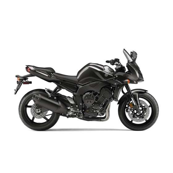
DESCRIPTION EAU10410 Left view 1. Front fork spring preload adjusting bolt (page 4-17) 9. Shock absorber assembly rebound damping force adjusting screw (page 4-19) 2. Front fork compression damping force adjusting screw (page 4-17) 10.Shift pedal (page 4-10) 3. Air filter element (page 7-15) 11.Engine oil drain bolt (page 7-11) 4. -
Page 17: Right View
DESCRIPTION EAU10420 Right view 1. Owner’s tool kit (page 7-2) 9. Brake pedal (page 4-11) 2. Rider seat lock lever (page 4-15) 10.Coolant reservoir (page 7-14) 3. Fuse box (page 7-32) 11.Rear brake light switch (page 7-22) 4. Battery (page 7-30) 12.Luggage strap holder (page 4-20) 5. -
Page 18: Controls And Instruments
DESCRIPTION EAU10430 Controls and instruments 1. Clutch lever (page 4-10) 2. Left handlebar switches (page 4-9) 3. Main switch/steering lock (page 4-1) 4. Multi-function meter unit (page 4-5) 5. Front brake fluid reservoir (page 7-23) 6. Right handlebar switches (page 4-9) 7. -
Page 19: Instrument And Control Functions
INSTRUMENT AND CONTROL FUNCTIONS EAU10460 EAU10661 To lock the steering Main switch/steering lock All electrical systems are off. The key can be removed. EWA10061 WARNING Never turn the key to “OFF” or “LOCK” while the vehicle is moving. Otherwise the electrical systems will be switched off, which may result in loss of control or an accident. -
Page 20: Indicator And Warning Lights
5. Engine trouble warning light “ ” or if the warning light remains on, have 6. Oil level warning light “ ” a Yamaha dealer check the electrical 7. Coolant temperature warning light “ ” circuit. EAU11030 Turn signal indicator lights “... - Page 21 2.5 seconds. If this occurs, the coolant temperature in the ra- have a Yamaha dealer check the diator. vehicle. If the engine overheats, see page 7-40 for further instructions.
- Page 22 INSTRUMENT AND CONTROL FUNCTIONS Coolant Display Conditions What to do temperature Under 39 °C Message “Lo” is displayed. OK. Go ahead with riding. (Under 103 °F) 40–116 °C Temperature is displayed. OK. Go ahead with riding. (104–242 °F) Stop the vehicle and allow it to idle until 117–134 °C Temperature display flashes.
-
Page 23: Multi-Function Meter Unit
If this oc- an odometer curs, have a Yamaha dealer check the two tripmeters (which show the self-diagnosis system. (See page 4-8 distance traveled since they were... - Page 24 INSTRUMENT AND CONTROL FUNCTIONS Tachometer Clock 5. Push the “RESET” button to set the minutes. 6. Push the “SELECT” button and then release it to start the clock. Odometer and tripmeter modes 1. Tachometer 1. Clock 2. Tachometer red zone The clock displays when the key is The electric tachometer allows the rider turned to “ON”.
- Page 25 5 km (3 mi). When the coolant temperature display mately 3 seconds. If this occurs, have a is selected, “C” is displayed for one Yamaha dealer check the electrical cir- Fuel meter second, and then the coolant tempera- cuit.
- Page 26 If the display indicates any error codes, the coolant temperature is auto- note the code number, and then have a matically displayed, even if the air Yamaha dealer check the vehicle. intake temperature was displayed ECA11590 NOTICE prior to turning the key to “OFF”.
-
Page 27: Handlebar Switches
INSTRUMENT AND CONTROL FUNCTIONS This function allows you to adjust the EAU12348 EAU12400 Handlebar switches Dimmer switch “ ” brightness of the LCD and the tachom- Set this switch to “ ” for the high eter panel and needle to suit the out- Left beam and to “... -
Page 28: Clutch Lever
INSTRUMENT AND CONTROL FUNCTIONS EAU12711 EAU12820 EAU12870 Start switch “ ” Clutch lever Shift pedal Push this switch to crank the engine with the starter. See page 6-1 for start- ing instructions prior to starting the en- gine. EAU41700 The engine trouble warning light will come on when the key is turned to “ON”... -
Page 29: Brake Lever
INSTRUMENT AND CONTROL FUNCTIONS EAU26823 EAU12941 EAU13074 Brake lever Brake pedal Fuel tank cap The brake lever is located at the right handlebar grip. To apply the front brake, pull the lever toward the handle- bar grip. 1. Brake pedal 1. -
Page 30: Fuel
INSTRUMENT AND CONTROL FUNCTIONS EAU13221 Fuel The fuel tank cap cannot be closed un- Make sure there is sufficient gasoline in less the key is in the lock. In addition, the tank. the key cannot be removed if the cap is EWA10881 WARNING not properly closed and locked. -
Page 31: Fuel Tank Breather/Overflow Hose
Before operating the motorcycle: as well as to the exhaust system. Check the fuel tank breather/over- Your Yamaha engine has been de- flow hose connection. signed to use regular unleaded gaso- Check the fuel tank breather/over-... -
Page 32: Catalytic Converters
INSTRUMENT AND CONTROL FUNCTIONS Make sure that the end of the fuel EAU13445 ECA10701 Catalytic converters NOTICE tank breather/overflow hose is po- This vehicle is equipped with catalytic sitioned inside of the clamp. Use only unleaded gasoline. The use converters in the exhaust system. of leaded gasoline will cause unre- EWA10862 pairable damage to the catalytic... -
Page 33: Seats
INSTRUMENT AND CONTROL FUNCTIONS EAU39322 Seats Passenger seat To remove the passenger seat 1. Insert the key into the seat lock, and then turn it counterclockwise. 1. Rider seat lock lever 2. Remove the key. To install the rider seat Rider seat 1. -
Page 34: Storage Compartment
INSTRUMENT AND CONTROL FUNCTIONS EAU14462 When washing the vehicle, be careful Storage compartment not to let any water enter the storage Make sure that the seats are properly compartment. secured before riding. 1. Storage compartment The storage compartment is located under the passenger seat. -
Page 35: Adjusting The Front Fork
INSTRUMENT AND CONTROL FUNCTIONS EAU39333 Spring preload Adjusting the front fork EWA14670 WARNING Always adjust the spring preload on both fork legs equally, otherwise poor handling and loss of stability may result. Each front fork leg is equipped with a spring preload adjusting bolt, the right 1. - Page 36 INSTRUMENT AND CONTROL FUNCTIONS Rebound damping force pression damping force and thereby Rebound damping setting: soften the compression damping, turn Minimum (soft): the adjusting screw in direction (b). 26 click(s) in direction (b)* Standard: 18 click(s) in direction (b)* Be sure to perform this adjustment on Maximum (hard): 1 click(s) in direction (b)* the left front fork leg.
-
Page 37: Adjusting The Shock Absorber Assembly
INSTRUMENT AND CONTROL FUNCTIONS EAU39344 To increase the spring preload and Rebound damping force Adjusting the shock absorber thereby harden the suspension, turn assembly the adjusting ring in direction (a). To de- This shock absorber assembly is crease the spring preload and thereby equipped with a spring preload adjust- soften the suspension, turn the adjust- ing ring and a rebound damping force... -
Page 38: Luggage Strap Holders
To obtain a precise adjustment, it is ad- sembly yourself. Take the shock visable to check the actual total number absorber assembly to a Yamaha of clicks or turns of the damping force dealer for any service. adjusting mechanism. This adjustment... -
Page 39: Exup System
INSTRUMENT AND CONTROL FUNCTIONS EAU41941 EAU15303 below and have a Yamaha dealer re- EXUP system Sidestand pair it if it does not function proper- This model is equipped with Yamaha’s The sidestand is located on the left side EXUP (EXhaust Ultimate Power valve) of the frame. -
Page 40: Ignition Circuit Cut-Off System
INSTRUMENT AND CONTROL FUNCTIONS EAU44902 Ignition circuit cut-off system The ignition circuit cut-off system (com- prising the sidestand switch, clutch switch and neutral switch) has the fol- lowing functions. It prevents starting when the trans- mission is in gear and the side- stand is up, but the clutch lever is not pulled. - Page 41 ”. stand during this inspection. • 3. Turn the key on. If a malfunction is noted, have a Yamaha 4. Shift the transmission into the neutral position. dealer check the system before riding. 5. Push the start switch. Does the engine start? With the engine still running: The neutral switch may not be working correctly.
-
Page 42: For Your Safety - Pre-Operation Checks
• If necessary, add recommended coolant to specified level. 7-14 • Check cooling system for leakage. • Check operation. • If soft or spongy, have Yamaha dealer bleed hydraulic system. • Check brake pads for wear. Front brake • Replace if necessary. - Page 43 • Make sure that operation is smooth. • Check cable free play. Throttle grip 7-18, 7-27 • If necessary, have Yamaha dealer adjust cable free play and lubricate cable and grip housing. • Make sure that operation is smooth. Control cables 7-26 •...
- Page 44 • Tighten if necessary. Instruments, lights, signals • Check operation. — and switches • Correct if necessary. • Check operation of ignition circuit cut-off system. Sidestand switch 4-21 • If system is not working correctly, have Yamaha dealer check vehicle.
-
Page 45: Operation And Important Riding Points
Yamaha dealer. The transmission is in the neutral a turnover. In this case, the multi-func- position. -
Page 46: Shifting
NOTICE tral position. (See page 6-2.) The neutral indicator light should come Even with the transmission in on. If not, ask a Yamaha dealer to the neutral position, do not check the electrical circuit. coast for long periods of time 3. -
Page 47: Engine Break-In
OPERATION AND IMPORTANT RIDING POINTS 4. At the recommended shift points 3. Shift the transmission into the neu- EAU16841 Engine break-in shown in the following table, close tral position when the motorcycle There is never a more important period the throttle, and at the same time, is almost completely stopped. -
Page 48: Parking
Yamaha dealer check the vehi- touch them and be burned. cle. Do not park on a slope or on soft... -
Page 49: Periodic Maintenance And Adjustment
(if applicable). Yamaha your risk of injury or death during dealers are trained and equipped to perform these particular services. -
Page 50: Owner's Tool Kit
If you do not have the tools or experi- ence required for a particular job, have a Yamaha dealer perform it for you. -
Page 51: Periodic Maintenance Chart For The Emission Control System
From 24000 mi (37000 km) or 36 months, repeat the maintenance intervals starting from 8000 mi (13000 km) or 12 months. Items marked with an asterisk require special tools, data and technical skills, have a Yamaha dealer perform the service. EAU17601... - Page 52 PERIODIC MAINTENANCE AND ADJUSTMENT INITIAL ODOMETER READINGS 600 mi 4000 mi 8000 mi 12000 mi 16000 mi 20000 mi ITEM ROUTINE (1000 km) (7000 km) (13000 km) (19000 km) (25000 km) (31000 km) 1 month 6 months 12 months 18 months 24 months 30 months Evaporative emis-...
-
Page 53: General Maintenance And Lubrication Chart
PERIODIC MAINTENANCE AND ADJUSTMENT EAU32186 General maintenance and lubrication chart INITIAL ODOMETER READINGS 600 mi 4000 mi 8000 mi 12000 mi 16000 mi 20000 mi ITEM ROUTINE (1000 km) (7000 km) (13000 km) (19000 km) (25000 km) (31000 km) 1 month 6 months 12 months 18 months... - Page 54 PERIODIC MAINTENANCE AND ADJUSTMENT INITIAL ODOMETER READINGS 600 mi 4000 mi 8000 mi 12000 mi 16000 mi 20000 mi ITEM ROUTINE (1000 km) (7000 km) (13000 km) (19000 km) (25000 km) (31000 km) 1 month 6 months 12 months 18 months 24 months 30 months •...
- Page 55 Front and rear brake √ √ √ √ √ √ 25 * • Check operation. switches • Apply Yamaha chain and cable √ √ √ √ √ √ 26 * Control cables lube or engine oil thoroughly. • Check operation and free play.
- Page 56 PERIODIC MAINTENANCE AND ADJUSTMENT INITIAL ODOMETER READINGS 600 mi 4000 mi 8000 mi 12000 mi 16000 mi 20000 mi ITEM ROUTINE (1000 km) (7000 km) (13000 km) (19000 km) (25000 km) (31000 km) 1 month 6 months 12 months 18 months 24 months 30 months Lights, signals and...
-
Page 57: Removing And Installing Panels
PERIODIC MAINTENANCE AND ADJUSTMENT EAU18771 Removing and installing pan- The panels shown need to be removed to perform some of the maintenance jobs described in this chapter. Refer to this section each time a panel needs to be removed and installed. 1. -
Page 58: Checking The Spark Plugs
Do not attempt to diagnose wipe off any grime from the spark plug such problems yourself. Instead, have threads. a Yamaha dealer check the vehicle. If a spark plug shows signs of electrode Tightening torque: Spark plug: erosion and excessive carbon or other 13 Nm (1.3 m·kgf, 9.4 ft·lbf) -
Page 59: Canister (For California Only)
PERIODIC MAINTENANCE AND ADJUSTMENT EAU19681 EAU19879 Canister (for California only) Engine oil and oil filter car- If a torque wrench is not available when tridge installing a spark plug, a good estimate The engine oil level should be checked of the correct torque is 1/4–1/2 turn before each ride. - Page 60 4. Minimum level mark An oil filter wrench is available at a 1. Engine oil drain bolt 4. If the engine oil is below the mini- Yamaha dealer. 2. Gasket mum level mark, add sufficient oil of the recommended type to raise 6.
- Page 61 PERIODIC MAINTENANCE AND ADJUSTMENT Recommended engine oil: See page 9-1. Oil quantity: Without oil filter cartridge replace- ment: 2.90 L (3.07 US qt, 2.55 Imp.qt) With oil filter cartridge replacement: 3.10 L (3.28 US qt, 2.73 Imp.qt) 1. O-ring 1. Torque wrench Be sure to wipe off spilled oil on any parts after the engine and exhaust sys- Tightening torque:...
-
Page 62: Coolant
C to access the coolant reser- off and have a Yamaha dealer check voir. (See page 7-9.) Make sure that the vehicle is posi- the vehicle. -
Page 63: Replacing The Air Filter Element
Have a periodic maintenance and lubrication be protected against frost and Yamaha dealer change the coolant. chart. Replace the air filter element corrosion. If water has been WARNING! Never attempt to remove... - Page 64 PERIODIC MAINTENANCE AND ADJUSTMENT 1. Bolt 1. Air filter element 6. Remove the air filter case cover by 2. Air intake manifold removing the screws. NOTICE: 5. Lift the front of the fuel tank, and When removing the air filter 8.
-
Page 65: Checking The Engine Idling Speed
Yamaha dealer. are not damaged. If any fuel hose is damaged, do not start Engine idling speed: the engine but have a Yamaha 1100–1300 r/min dealer replace the hose, other- wise fuel may leak, creating a fire hazard. -
Page 66: Checking The Throttle Cable Free Play
To prevent this cle, note the following points regarding from occurring, the valve clearance the specified tires. must be adjusted by a Yamaha dealer at the intervals specified in the periodic Tire air pressure maintenance and lubrication chart. - Page 67 FZS10ZC 189 kg (417 lb) in it, or if the sidewall is cracked, con- * Total weight of rider, passenger, car- tact a Yamaha dealer immediately and go and accessories have the tire replaced. EWA10511...
- Page 68 Yamaha Motor Co., Ltd. Use only the specified replace- ment tires. Other tires may run the danger of bursting at super high speeds.
-
Page 69: Cast Wheels
Yamaha dealer check the internal specified wheels. clutch mechanism. The wheel rims should be checked for cracks, bends or warpage be- fore each ride. -
Page 70: Checking The Brake Lever Free Play
If there is free play, come on just before braking takes ef- have a Yamaha dealer inspect the fect. If necessary, adjust the rear brake brake system. light switch as follows, but the front... -
Page 71: Checking The Front And Rear Brake Pads
EAU22571 Checking the front and rear Checking the brake fluid level touches the brake disc, have a Yamaha brake pads dealer replace the brake pads as a set. Front brake The front and rear brake pads must be... -
Page 72: Changing The Brake Fluid
Changing the brake fluid is above the minimum level mark and ter the brake fluid reservoir when Have a Yamaha dealer change the replenish if necessary. A low brake fluid refilling. Water will significantly brake fluid at the intervals specified in... -
Page 73: Drive Chain Slack
PERIODIC MAINTENANCE AND ADJUSTMENT EAU22760 Drive chain slack: Drive chain slack 20.0–30.0 mm (0.79–1.18 in) Using the alignment marks on each The drive chain slack should be side of the swingarm, make sure that checked before each ride and adjusted 5. -
Page 74: Cleaning And Lubricating The Drive Chain
If a cable is damaged wet areas. Service the drive chain as or does not move smoothly, have a follows. Yamaha dealer check or replace it. ECA10583 WARNING! Damage to the outer NOTICE housing of cables may result in in-... -
Page 75: Checking And Lubricating The Throttle Grip And Cable
The operation of the throttle grip should Brake pedal be checked before each ride. In addi- tion, the cable should be lubricated by a Yamaha dealer at the intervals speci- fied in the periodic maintenance chart. Shift pedal The operation of the brake and shift... -
Page 76: Checking And Lubricating The Brake And Clutch Levers
EWA10741 WARNING If the centerstand or sidestand does not move up and down smoothly, have a Yamaha dealer check or re- pair it. Otherwise, the centerstand or sidestand could contact the ground The operation of the brake and clutch and distract the operator, resulting levers should be checked before each in a possible loss of control. -
Page 77: Checking The Front Fork
If any damage is found or the front face and hold it in an upright posi- fork does not operate smoothly, tion. WARNING! To avoid injury, have a Yamaha dealer check or re- securely support the vehicle so pair it. there is no danger of it falling over. -
Page 78: Checking The Steering
If any free (Valve Regulated Lead Acid) battery. hub or if the wheel does not turn play can be felt, have a Yamaha There is no need to check the electro- smoothly, have a Yamaha dealer check dealer check or repair the steering. - Page 79 [ECA16302] To charge the battery 2. If the battery will be stored for more Have a Yamaha dealer charge the bat- than two months, check it at least tery as soon as possible if it seems to once a month and fully charge it if have discharged.
-
Page 80: Replacing The Fuses
PERIODIC MAINTENANCE AND ADJUSTMENT EAU43011 Replacing the fuses The main fuse, the fuel injection system fuse, and the fuse box, which contains the fuses for the individual circuits, are located under the rider seat. (See page 4-15.) 1. Fuse box 1. -
Page 81: Replacing A Headlight Bulb
Headlight lens 5. If the fuse immediately blows Do not affix any type of tinted again, have a Yamaha dealer film or stickers to the headlight 1. Headlight coupler check the electrical system. lens. -
Page 82: Replacing The Tail/Brake Light Bulb
4. Install the headlight bulb cover, 1. Turn signal light unit and then connect the coupler. 2. Screw 5. Have a Yamaha dealer adjust the 2. Remove the socket (together with headlight beam if necessary. 1. Tail/brake light bulb socket the bulb) by turning it counter- clockwise. -
Page 83: Replacing The License Plate Light Bulb
PERIODIC MAINTENANCE AND ADJUSTMENT 6. Install the turn signal light unit by EAU24313 Replacing the license plate installing the screw. NOTICE: Do light bulb not overtighten the screw, oth- 1. Remove the license plate light unit erwise the lens may break. by removing the screws. -
Page 84: Front Wheel
PERIODIC MAINTENANCE AND ADJUSTMENT EAU24360 3. Remove the brake hose holder on Front wheel each side by removing the bolt and nut. EAU40201 4. Remove the brake caliper (togeth- To remove the front wheel er with the reflector) on each side EWA10821 WARNING by removing the bolts. -
Page 85: Rear Wheel
PERIODIC MAINTENANCE AND ADJUSTMENT EAU40211 EAU25080 Tightening torques: To install the front wheel Rear wheel Wheel axle: 1. Lift the wheel up between the fork 72 Nm (7.2 m·kgf, 52 ft·lbf) legs. EAU40022 Front wheel axle pinch bolt: To remove the rear wheel 2. -
Page 86: To Install The Rear Wheel
PERIODIC MAINTENANCE AND ADJUSTMENT NOTICE: Do not apply the brake after the wheel has been re- moved together with the brake disc, otherwise the brake pads will be forced shut. [ECA11071] 1. Drive chain slack adjusting bolt 1. Slot 2. Locknut 2. -
Page 87: Troubleshooting
The following troubleshooting charts represent quick and easy procedures for checking these vital systems your- self. However, should your motorcycle require any repair, take it to a Yamaha dealer, whose skilled technicians have the necessary tools, experience, and know-how to service the motorcycle properly. -
Page 88: Troubleshooting Charts
Remove the spark plugs and check the electrodes. The engine does not start. Have a Yamaha dealer check the vehicle. Check the battery. 4. Battery The engine turns over The battery is good. - Page 89 Start the engine. If the engine overheats again, have a The coolant level Yamaha dealer check and repair the cooling system. is OK. If coolant is not available, tap water can be temporarily used instead, provided that it is changed to the recommended coolant as soon as possible.
-
Page 90: Motorcycle Care And Storage
Be ble. Rust and corrosion can develop Cleaning even if high-quality components are sure to consult a Yamaha dealer for ECA10772 used. A rusty exhaust pipe may go un- advice on what products to use be- NOTICE fore cleaning the vehicle. - Page 91 MOTORCYCLE CARE AND STORAGE off any detergent residue using Test the product on a small hid- plenty of water, as it is harmful den part of the windshield to Salt sprayed on roads in the winter may to plastic parts. make sure that it does not leave remain well into spring.
-
Page 92: Storage
WARNING To prevent corrosion, avoid Contaminants on the brakes or tires Consult a Yamaha dealer for ad- damp cellars, stables (because can cause loss of control. vice on what products to use. of the presence of ammonia) - Page 93 MOTORCYCLE CARE AND STORAGE 3. Perform the following steps to pro- 4. Lubricate all control cables and the tect the cylinders, piston rings, etc. pivoting points of all levers and from corrosion. pedals as well as of the side- a. Remove the spark plug caps stand/centerstand.
-
Page 94: Specifications
SPECIFICATIONS Dimensions: Engine oil: Fuel: Overall length: Recommended brand: Recommended fuel: 2140 mm (84.3 in) YAMALUBE Unleaded gasoline only Overall width: Type: Fuel tank capacity: 770 mm (30.3 in) SAE 10W-30, 10W-40, 10W-50, 15W-40, 18.0 L (4.76 US gal, 3.96 Imp.gal) Overall height: 20W-40 or 20W-50 Fuel reserve amount:... - Page 95 SPECIFICATIONS Gear ratio: Loading: Rim size: 1st: 17M/C x MT6.00 Maximum load: 38/15 (2.533) Front brake: FZS10Z 190 kg (419 lb) 2nd: FZS10ZC 189 kg (417 lb) Type: 33/16 (2.063) (Total weight of rider, passenger, cargo and Dual disc brake 3rd: accessories) Operation:...
- Page 96 SPECIFICATIONS Charging system: Engine trouble warning light: AC magneto Battery: Fuses: Model: Main fuse: YTZ14S 50.0 A Voltage, capacity: Headlight fuse: 12 V, 11.2 Ah 20.0 A Headlight: Signaling system fuse: 10.0 A Bulb type: Ignition fuse: Halogen bulb Bulb voltage, wattage × quantity: 15.0 A Radiator fan fuse: Headlight:...
-
Page 97: Consumer Information
Record the key identification number, vehicle identification number and mod- el label information in the spaces pro- vided below for assistance when ordering spare parts from a Yamaha dealer or for reference in case the vehi- cle is stolen. KEY IDENTIFICATION NUMBER: 1. - Page 98 This information illustration. This label shows specifica- will be needed when ordering spare tions related to exhaust emissions as parts from a Yamaha dealer. required by federal law, state law and Environment Canada. 10-2...
-
Page 99: Reporting Safety Defects
If you believe that your vehicle has a defect which could cause a crash or could cause injury or death, you should immediately inform the National Highway Traffic Safety Administration (NHTSA) in addition to notifying Yamaha Motor Corporation, U.S.A. If NHTSA receives similar complaints, it may open an investigation, and if it finds that a safety defect exists in a group of vehicles, it may order a recall and remedy campaign. -
Page 100: Motorcycle Noise Regulation
CONSUMER INFORMATION EAU26560 Motorcycle noise regulation TAMPERING WITH NOISE CONTROL SYSTEM PROHIBITED: Federal law prohibits the following acts or the causing thereof: (1) The removal or rendering inoperative by any person other than for purposes of maintenance, repair, or replacement of any device or element of design incorporated into any new ve- hicle for the purpose of noise control prior to its sale or delivery to the ultimate purchaser or while it is in use or (2) the use of the vehicle after such device or element of design has been removed or rendered inoperative by any person. -
Page 101: Maintenance Record
CONSUMER INFORMATION EAU26632 Maintenance record Copies of work orders and/or receipts for parts purchased and installed on your vehicle will be required to document that maintenance has been completed in accordance with the emissions warranty. The chart below is printed only as a reminder that maintenance work is required. - Page 102 CONSUMER INFORMATION Maintenance Date of Servicing dealer Mileage Remarks interval service name and address 36000 mi (55000 km) or 54 months 40000 mi (61000 km) or 60 months 10-6...
-
Page 103: Yamaha Motor
CONSUMER INFORMATION EAU26663 YAMAHA MOTOR CORPORATION, U.S.A. STREET AND ENDURO MOTORCYCLE LIMITED WARRANTY Yamaha Motor Corporation, U.S.A. hereby warrants that CUSTOMER’S RESPONSIBILITY under this Engine new Yamaha motorcycles will be free from defects in warranty shall be to: Displacement Period... - Page 104 CUSTOMER SERVICE What costs are my responsibility during the warranty period? If your machine requires warranty service, you must take it to any authorized Yamaha The customer’s responsibility includes all costs of normal maintenance services, motorcycle dealer within the continental United States. Be sure to bring your warranty non-warranty repairs, accident and collision damages, and oil, oil filters, air filters, registration card or other valid proof of the original date of purchase.
-
Page 105: Yamaha Extended Service (Y.e.s.)
This excellent Y.E.S. plan coverage is only available to dealer to see how comforting uninterrupted factory- Yamaha owners like you, and only while your Yamaha is still backed protection can be. within the Yamaha Limited Warranty period. So visit your authorized Yamaha dealer to get all the facts. - Page 106 Yamaha Limited Warranty expires. A special note: If visiting your dealer isn’t convenient, contact Yamaha with your Primary ID number (your frame number). We’ll be happy to help you get the Y.E.S. coverage you need.
- Page 107 INDEX Engine trouble warning light ....4-5 EXUP system ........4-21 Air filter element, replacing ....7-15 Neutral indicator light ......4-2 Noise regulation........10-4 Front and rear brake pads, checking ..7-23 Battery ..........7-30 Front fork, adjusting ......4-17 Brake and clutch levers, checking and Oil level warning light ......
- Page 108 INDEX Turn signal light bulb, replacing .... 7-34 Turn signal switch ........4-9 Valve clearance ........7-18 Vehicle Emission Control Information label ............ 10-2 Vehicle identification number ....10-1 Warranty, extended....... 10-9 Warranty, limited ........10-7 Wheel bearings, checking..... 7-30 Wheel (front) .........
- Page 110 YAMAHA MOTOR CO., LTD. PRINTED ON RECYCLED PAPER PRINTED IN JAPAN 2009.12-0.3×1 CR...
Need help?
Do you have a question about the FZS10Z and is the answer not in the manual?
Questions and answers