Table of Contents
Advertisement
Quick Links
Advertisement
Table of Contents
Troubleshooting

Subscribe to Our Youtube Channel
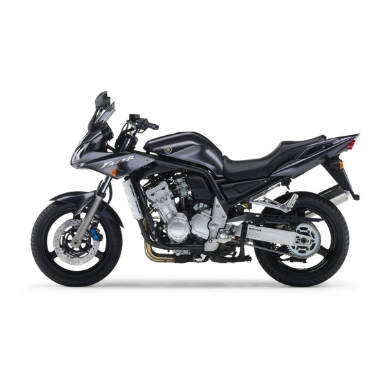
Related Manuals for Yamaha FZS1000T


Summary of Contents for Yamaha FZS1000T
- Page 1 OWNER’S MANUAL FZS1000T 1C2-28199-21...
- Page 3 Welcome to the Yamaha world of motorcycling! As the owner of the FZS1000, you are benefiting from Yamaha’s vast experience and newest technology regarding the de- sign and manufacture of high-quality products, which have earned Yamaha a reputation for dependability.
- Page 4 This manual should be considered a permanent part of this motorcycle and should remain with it even if the motorcycle is subsequently sold. Yamaha continually seeks advancements in product design and quality. Therefore, while this manual contains the most current product information available at the time of printing, there may be minor discrepancies between your motorcycle and this manual.
- Page 5 IMPORTANT MANUAL INFORMATION EAU10200 FZS1000T OWNER’S MANUAL ©2004 by Yamaha Motor Co., Ltd. 1st edition, September 2004 All rights reserved. Any reprinting or unauthorized use without the written permission of Yamaha Motor Co., Ltd. is expressly prohibited. Printed in Japan.
-
Page 6: Table Of Contents
TABLE OF CONTENTS SAFETY INFORMATION ....1-1 Sidestand ........3-15 Checking the throttle cable free Location of important labels ....1-5 Ignition circuit cut-off system ..3-16 play ........... 6-17 Valve clearance ......6-17 DESCRIPTION ........2-1 PRE-OPERATION CHECKS ..... 4-1 Tires ..........6-17 Left view ..........2-1 Pre-operation check list .... - Page 7 TABLE OF CONTENTS Battery ..........6-29 Replacing the fuses ......6-30 Replacing a headlight bulb ...6-31 Replacing a tail/brake light bulb ...6-32 Replacing a turn signal light bulb ...........6-33 Front wheel ........6-33 Rear wheel ........6-35 Troubleshooting ......6-36 Troubleshooting charts ....6-37 MOTORCYCLE CARE AND STORAGE ..........7-1 Care ..........7-1 Storage ...........7-3...
-
Page 8: Safety Information
SAFETY INFORMATION EAU10272 AND/OR WHEN MADE NECES- • Ride where other motorists can SARY BY MECHANICAL CONDI- see you. Avoid riding in another MOTORCYCLES SINGLE TIONS. motorist’s blind spot. TRACK VEHICLES. THEIR SAFE USE Many accidents involve inexperi- AND OPERATION ARE DEPENDENT Safe riding enced operators. - Page 9 Modifications made to this motorcycle other motorists can see you. the single most critical factor in the pre- not approved by Yamaha, or the re- The posture of the operator and vention or reduction of head injuries. moval of original equipment, may ren- passenger is important for proper Always wear an approved helmet.
- Page 10 Maximum load: been specifically designed for use on create instability due to improper 189 kg (417 lb) this motorcycle. Since Yamaha cannot weight distribution or aerody- test all other accessories that may be namic changes. If accessories When loading within this weight limit,...
- Page 11 SAFETY INFORMATION tor and may limit control ability, Always turn the engine off before or clothing, immediately wash the therefore, such accessories are leaving the motorcycle unattended affected area with soap and water not recommended. and remove the key from the main and change your clothes.
-
Page 12: Location Of Important Labels
SAFETY INFORMATION EAU10381 Location of important labels Please read the following important labels carefully before operating this vehicle. Before you operate this vehicle, read the owner’s manual. Prima di usare il veicolo, leggete il manuale di istruzioni. Lire le manuel du propriétaire avant d’utiliser ce véhicule. Lesen Sie die Bedienungsanleitung bevor Sie dieses Fahrzeug fahren. -
Page 13: Description
DESCRIPTION EAU10410 Left view 1. Front fork compression damping force adjusting screw (page 3-11) 11.Shock absorber assembly spring preload adjusting ring (page 3-13) 2. Front fork rebound damping force adjusting screw (page 3-11) 12.Shock absorber assembly rebound damping force adjusting knob (page 3-13) 3. -
Page 14: Right View
DESCRIPTION EAU10420 Right view 1. Owner’s tool kit (page 6-1) 2. Rear brake fluid reservoir (page 6-22) 3. Battery (page 6-29) 4. Front brake fluid reservoir (page 6-22) 5. Radiator cap (page 6-11) 6. Engine oil filter cartridge (page 6-8) 7. -
Page 15: Controls And Instruments
DESCRIPTION EAU10430 Controls and instruments 1. Clutch lever (page 3-6) 2. Left handlebar switches (page 3-5) 3. Starter (choke) lever (page 3-9) 4. Speedometer unit (page 3-3) 5. Main switch/steering lock (page 3-1) 6. Tachometer unit (page 3-4) 7. Fuel gauge (page 3-5) 8. -
Page 16: Instrument And Control Functions
INSTRUMENT AND CONTROL FUNCTIONS EAU10460 EAU10680 To unlock the steering Main switch/steering lock LOCK The steering is locked, and all electrical systems are off. The key can be re- moved. To lock the steering 1. Push. 2. Turn. The main switch/steering lock controls the ignition and lighting systems, and is Push the key in, and then turn it to used to lock the steering. -
Page 17: Indicator And Warning Lights
“ON”. 1. Left turn signal indicator light “ ” Yamaha dealer check the electrical cir- 2. Neutral indicator light “ ” If the warning light does not come on cuit. -
Page 18: Speedometer Unit
INSTRUMENT AND CONTROL FUNCTIONS ECA10020 EAU11810 be traveled on a full tank of fuel. This in- Speedometer unit CAUTION: formation will enable you to plan future fuel stops. Do not operate the engine if it is overheated. To set a mode Push the “SELECT”... -
Page 19: Tachometer Unit
INSTRUMENT AND CONTROL FUNCTIONS EAU11891 To set the clock EAU12101 Tachometer unit Self-diagnosis devices 1. Push both the “SELECT” and “RE- This model is equipped with a self-diag- SET” buttons for at least two sec- nosis device for the following electrical onds. -
Page 20: Fuel Gauge
If the tachometer displays such an error EAU12110 EAU12343 Fuel gauge Handlebar switches code, note the circuit-specific number of r/min, and then have a Yamaha deal- Left er check the vehicle. ECA10040 CAUTION: When the tachometer displays an er- ror code, the vehicle should be checked as soon as possible in or- der to avoid engine damage. -
Page 21: Clutch Lever
INSTRUMENT AND CONTROL FUNCTIONS EAU12360 EAU12710 EAU12820 Pass switch “PASS” Start switch “ ” Clutch lever Press this switch to flash the headlight. Push this switch to crank the engine with the starter. EAU12400 ECA10050 Dimmer switch “ ” CAUTION: Set this switch to “... -
Page 22: Shift Pedal
INSTRUMENT AND CONTROL FUNCTIONS EAU12870 EAU12930 EAU12941 Shift pedal Brake lever Brake pedal The brake lever is located at the right handlebar grip. To apply the front brake, pull the lever toward the handle- bar grip. 1. Shift pedal 1. Brake pedal The shift pedal is located on the left The brake pedal is on the right side of side of the engine and is used in com-... -
Page 23: Fuel Tank Cap
INSTRUMENT AND CONTROL FUNCTIONS EAU13070 EAU13210 Fuel tank cap NOTE: Fuel The fuel tank cap cannot be closed un- less the key is in the lock. In addition, the key cannot be removed if the cap is not properly closed and locked. EWA11090 WARNING Make sure that the fuel tank cap is... -
Page 24: Starter (Choke) Lever
Your Yamaha engine has been de- signed to use regular unleaded gaso- line with a research octane number of 91 or higher. If knocking (or pinging) oc-... -
Page 25: Seat
INSTRUMENT AND CONTROL FUNCTIONS EAU13940 EAU14290 Seat Helmet holder To remove the seat 1. Insert the key into the seat lock, and then turn it clockwise. 1. Projection 2. Seat holder 1. Helmet holder 2. Push the rear of the seat down to 2. -
Page 26: Storage Compartment
INSTRUMENT AND CONTROL FUNCTIONS EAU14451 When washing the vehicle, be careful EAU14751 Storage compartment Adjusting the front fork not to let any water enter the storage This front fork is equipped with spring compartment. preload adjusting bolts, rebound damp- ing force adjusting screws and com- pression damping force... - Page 27 INSTRUMENT AND CONTROL FUNCTIONS load thereby soften Rebound damping force Compression damping force suspension, turn the adjusting bolt on each fork leg in direction (b). NOTE: Align the appropriate groove on the ad- justing mechanism with the top of the front fork cap bolt.
-
Page 28: Adjusting The Shock Absorber Assembly
INSTRUMENT AND CONTROL FUNCTIONS ECA10100 EAU15041 To increase the spring preload and Adjusting the shock absorber CAUTION: thereby harden the suspension, turn assembly the adjusting ring in direction (a). To de- Never attempt to turn an adjusting This shock absorber assembly is crease the spring preload and thereby mechanism beyond the maximum or equipped with a spring preload adjust-... - Page 29 INSTRUMENT AND CONTROL FUNCTIONS Rebound damping force Compression damping force NOTE: Although the total number of clicks of a damping force adjusting mechanism may not exactly match the above spec- ifications due to small differences in production, the actual number of clicks always represents the entire adjusting range.
-
Page 30: Exup System
EAU15300 EXUP system Sidestand sorber to an open flame or other This model is equipped with Yamaha’s The sidestand is located on the left side high heat sources, otherwise it EXUP (EXhaust Ultimate Power valve) of the frame. Raise the sidestand or may explode due to excessive system. -
Page 31: Ignition Circuit Cut-Off System
INSTRUMENT AND CONTROL FUNCTIONS below and have a Yamaha dealer re- EAU15321 Ignition circuit cut-off system pair it if it does not function proper- The ignition circuit cut-off system (com- prising the sidestand switch, clutch switch and neutral switch) has the fol- lowing functions. - Page 32 5. Push the start switch. Does the engine start? The neutral switch may be defective. The motorcycle should not be ridden until checked by a Yamaha dealer. With the engine still running: 6. Move the sidestand up. 7. Keep the clutch lever pulled.
-
Page 33: Pre-Operation Checks
PRE-OPERATION CHECKS EAU15591 The condition of a vehicle is the owner’s responsibility. Vital components can start to deteriorate quickly and unexpectedly, even if the vehicle remains unused (for example, as a result of exposure to the elements). Any damage, fluid leakage or loss of tire air pressure could have serious consequences. -
Page 34: Pre-Operation Check List
• If necessary, add recommended coolant to specified level. 6-11 • Check cooling system for leakage. • Check operation. • If soft or spongy, have Yamaha dealer bleed hydraulic system. • Check brake pads for wear. Front brake • Replace if necessary. - Page 35 • Make sure that operation is smooth. • Check cable free play. Throttle grip 6-17, 6-25 • If necessary, have Yamaha dealer adjust cable free play and lubricate cable and grip housing. • Make sure that operation is smooth. Control cables 6-25 •...
-
Page 36: Operation And Important Riding Points
Never start the engine or oper- EWA10290 Yamaha dealer check the electrical cir- WARNING ate it in a closed area for any cuit. length of time. Exhaust fumes Before... - Page 37 Yamaha dealer check the with sufficient engine oil, have a electrical circuit. Yamaha dealer check the elec- trical circuit.
-
Page 38: Starting A Warm Engine
OPERATION AND IMPORTANT RIDING POINTS EAU16640 EAU16671 ECA10260 Starting a warm engine Shifting CAUTION: Follow the same procedure as for start- Even with the transmission in ing a cold engine with the exception the neutral position, do not that the starter (choke) is not required coast for long periods of time when the engine is warm. -
Page 39: Tips For Reducing Fuel Consumption
(e.g., in traffic jams, at traffic period, immediately have a lights or at railroad crossings). Yamaha dealer check the vehi- EAU17091 cle. 0–1000 km (0–600 mi) Avoid prolonged operation above 5800 r/min. -
Page 40: Parking
OPERATION AND IMPORTANT RIDING POINTS EAU17200 Parking When parking, stop the engine, and then remove the key from the main switch. EWA10310 WARNING Since the engine and exhaust system can become very hot, park in a place where pedestri- ans or children are not likely to touch them. -
Page 41: Periodic Maintenance And Minor Repair
Yamaha dealer certain maintenance work correctly. do it for you. NOTE: If you do not have the tools or experi- ence required for a particular job, have a Yamaha dealer perform it for you. -
Page 42: Periodic Maintenance And Lubrication Chart
The annual checks must be performed every year, except if a kilometer-based maintenance is performed in- stead. From 50000 km, repeat the maintenance intervals starting from 10000 km. Items marked with an asterisk should be performed by a Yamaha dealer as they require special tools, data and technical skills. ODOMETER READING (× 1000 km) - Page 43 PERIODIC MAINTENANCE AND MINOR REPAIR ODOMETER READING (× 1000 km) ANNUAL ITEM CHECK OR MAINTENANCE JOB CHECK √ √ √ √ √ • Check for cracks or damage. 9 * Brake hoses • Replace. Every 4 years √ √ √ √...
- Page 44 PERIODIC MAINTENANCE AND MINOR REPAIR ODOMETER READING (× 1000 km) ANNUAL ITEM CHECK OR MAINTENANCE JOB CHECK • Check starter (choke) operation. √ √ √ √ √ √ 22 * Carburetors • Adjust engine idling speed and synchronization. • Change. √...
- Page 45 PERIODIC MAINTENANCE AND MINOR REPAIR Hydraulic brake service • Regularly check and, if necessary, correct the brake fluid level. • Every two years replace the internal components of the brake master cylinders and calipers, and change the brake fluid. • Replace the brake hoses every four years and if cracked or damaged.
-
Page 46: Removing And Installing Panels
PERIODIC MAINTENANCE AND MINOR REPAIR EAU18771 Removing and installing panels The panels shown need to be removed to perform some of the maintenance jobs described in this chapter. Refer to this section each time a panel needs to be removed and installed. 1. -
Page 47: Checking The Spark Plugs
Do not attempt to diagnose such 1. Spark plug cap problems yourself. Instead, have a 2. Remove the spark plug as shown, Yamaha dealer check the vehicle. with the spark plug wrench includ- ed in the owner’s tool kit. -
Page 48: Engine Oil And Oil Filter Cartridge
PERIODIC MAINTENANCE AND MINOR REPAIR 3. Check each spark plug for elec- 2. Clean the surface of the spark plug EAU19890 Engine oil and oil filter trode erosion and excessive car- gasket and its mating surface, and cartridge bon or other deposits, and replace then wipe off any grime from the The engine oil level should be checked it if necessary. - Page 49 2. Oil filter cartridge NOTE: An oil filter wrench is available at a 1. Engine oil filler cap Yamaha dealer. 2. Engine oil level check window 1. Engine oil drain bolt 3. Maximum level mark 5. Apply a thin coat of engine oil to 4.
- Page 50 PERIODIC MAINTENANCE AND MINOR REPAIR Recommended engine oil: See page 8-1. Oil quantity: Without oil filter cartridge replace- ment: 2.80 L (2.96 US qt) (2.46 Imp.qt) With oil filter cartridge replacement: 3.00 L (3.17 US qt) (2.64 Imp.qt) ECA11620 CAUTION: 1.
-
Page 51: Coolant
If the oil level warning light flickers EAU20101 or remains on, immediately turn the To check the coolant level engine off and have a Yamaha dealer 1. Place the vehicle on the center- 1. Coolant reservoir check the vehicle. stand. - Page 52 2. Remove panels A and B. (See If water has been added to the page 6-6.) coolant, have a Yamaha dealer 3. Place a container under the engine check the antifreeze content of to collect the used coolant.
- Page 53 If ant as soon as possible, other- 7 Nm (0.7 m·kgf, 5 ft·lbf) coolant is leaking, have a Yamaha wise the engine may not be sufficiently cooled and the cool- dealer check the cooling system.
-
Page 54: Cleaning The Air Filter Element
PERIODIC MAINTENANCE AND MINOR REPAIR EAU20681 Do not tilt or pull the fuel tank Cleaning the air filter element too much, otherwise the fuel The air filter element should be cleaned hoses may come loose, which at the intervals specified in the periodic could cause fuel leakage. - Page 55 Before installing the fuel tank, make sure that the fuel hoses are not damaged. If any fuel hose is damaged, do not start the engine but have a Yamaha dealer replace the hose, other- wise fuel may leak. Make sure that the fuel hoses are properly connected and 1.
-
Page 56: Adjusting The Carburetors
Therefore, most carbu- checked and, if necessary, adjusted as retor adjustments should be left to a follows at the intervals specified in the Yamaha dealer, who has the neces- periodic maintenance and lubrication sary professional knowledge and expe- chart. -
Page 57: Checking The Throttle Cable Free Play
Yamaha dealer at the intervals specified in the periodic Tire air pressure maintenance and lubrication chart. The tire air pressure should be checked and, if necessary, adjusted before each ride. - Page 58 LOAD YOUR VEHICLE. Make sure in it, or if the sidewall is cracked, con- Rear: that the total weight of the cargo, rid- tact a Yamaha dealer immediately and 270 kPa (39 psi) (2.70 kgf/cm²) er, passenger, and accessories have the tire replaced.
- Page 59 This motorcycle is fitted with super- from country to country. Always comply Yamaha Motor Co., Ltd. high-speed tires. Note the following with the local regulations. Always make sure that the valve points in order to make the most ef- caps are securely installed to ficient use of these tires.
-
Page 60: Cast Wheels
Yamaha dealer check the internal specified wheels. clutch mechanism. The wheel rims should be checked for cracks, bends or warpage be- fore each ride. -
Page 61: Adjusting The Rear Brake Light Switch
If a brake pad has worn to the point that the wear indicator groove has almost disappeared, have a Yamaha dealer replace the brake pads as a set. 1. Rear brake light switch 2. Rear brake light switch adjusting nut 1. -
Page 62: Checking The Brake Fluid Level
However, if the Use only the recommended quality brake fluid level goes down sud- 1. Minimum level mark brake fluid, otherwise the rubber denly, have a Yamaha dealer Rear brake seals may deteriorate, causing check the cause. leakage and poor braking perfor- mance. -
Page 63: Changing The Brake Fluid
Drive chain slack: Changing the brake fluid Drive chain slack 40.0–50.0 mm (1.57–1.97 in) Have a Yamaha dealer change the The drive chain slack should be brake fluid at the intervals specified in checked before each ride and adjusted 5. If the drive chain slack is incorrect, the NOTE after the periodic mainte- if necessary. -
Page 64: Lubricating The Drive Chain
PERIODIC MAINTENANCE AND MINOR REPAIR EAU23021 Tightening torque: Lubricating the drive chain Axle nut: The drive chain must be cleaned and 150 Nm (15.0 m·kgf, 108 ft·lbf) lubricated at the intervals specified in the periodic maintenance and lubrica- tion chart, otherwise it will quickly wear out, especially when riding in dusty or wet areas. -
Page 65: Checking And Lubricating The Cables
If a cable is damaged periodic maintenance chart. or does not move smoothly, have a Yamaha dealer check or replace it. Recommended lubricant: Engine oil EWA10720 WARNING... -
Page 66: Checking And Lubricating The Brake And Shift Pedals
Lithium-soap-based grease (all-pur- Lithium-soap-based grease (all-pur- WARNING pose grease) pose grease) If the centerstand or sidestand does not move up and down smoothly, have a Yamaha dealer check or re- pair it. Recommended lubricant: Lithium-soap-based grease (all-pur- pose grease) 6-26... -
Page 67: Lubricating The Swingarm Pivots
PERIODIC MAINTENANCE AND MINOR REPAIR EAUM1650 EAU23250 EAU23271 Lubricating the swingarm Lubricating the rear Checking the front fork pivots suspension The condition and operation of the front fork must be checked as follows at the The swingarm pivots must be lubricat- The pivoting points of the rear suspen- intervals specified in the periodic main- ed at the intervals specified in the peri-... -
Page 68: Checking The Steering
Securely support the vehicle so that fork does not operate smoothly, there is no danger of it falling over. have a Yamaha dealer check or re- pair it. 2. Hold the lower ends of the front fork legs and try to move them for- ward and backward. -
Page 69: Checking The Wheel Bearings
To charge the battery burns. Avoid any contact with Have a Yamaha dealer charge the bat- skin, eyes or clothing and al- tery as soon as possible if it seems to ways shield your eyes when have discharged. -
Page 70: Replacing The Fuses
Replacing the fuses if the vehicle is equipped with optional sealed-type (MF) battery charg- electrical accessories. er, have a Yamaha dealer charge your battery. To store the battery 1. If the vehicle will not be used for more than one month, remove the battery, fully charge it, and then place it in a cool, dry place. -
Page 71: Replacing A Headlight Bulb
2. Headlight coupler CAUTION: 4. If the fuse immediately blows Take care not to damage the follow- 3. Unhook the headlight bulb holder, again, have a Yamaha dealer ing parts: and then remove the defective check the electrical system. bulb. -
Page 72: Replacing A Tail/Brake Light Bulb
6. Install the panel. 1. Remove the seat. (See page from oil, otherwise the transpar- 7. Have a Yamaha dealer adjust the 3-10.) ency of the glass, the luminosity headlight beam if necessary. -
Page 73: Replacing A Turn Signal Light Bulb
1. Remove the turn signal light lens To remove the front wheel by removing the screw. EWA10820 WARNING It is advisable to have a Yamaha dealer service the wheel. Securely support the motor- cycle so that there is no danger 1. Tail/brake light bulb socket of it falling over. - Page 74 PERIODIC MAINTENANCE AND MINOR REPAIR 3. Remove the brake hose holder EAU33770 7. Push down hard on the handlebar To install the front wheel and reflector on each side by re- several times to check for proper 1. Lift the wheel up between the fork moving the bolts.
-
Page 75: Rear Wheel
To remove the rear wheel rear sprocket. EWA10820 WARNING It is advisable to have a Yamaha dealer service the wheel. Securely support the motor- cycle so that there is no danger of it falling over. -
Page 76: Troubleshooting
However, should your motorcycle require any repair, take it to a Yamaha Tightening torques: dealer, whose skilled technicians have Axle nut: 150 Nm (15.0 m·kgf, 108 ft·lbf) -
Page 77: Troubleshooting Charts
Remove the spark plugs and check the electrodes. The engine does not start. Have a Yamaha dealer check the vehicle. Check the battery. 4. Battery The engine turns over The battery is good. - Page 78 Start the engine. If the engine overheats again, have a The coolant level Yamaha dealer check and repair the cooling system. is OK. NOTE: If coolant is not available, tap water can be temporarily used instead, provided that it is changed to the recommended coolant as soon as possible.
-
Page 79: Motorcycle Care And Storage
MOTORCYCLE CARE AND STORAGE EAU26010 ucts onto seals, gaskets, sprock- cleaning products, solvent or Care ets, the drive chain and wheel thinner, fuel (gasoline), rust re- While the open design of a motorcycle axles. Always rinse the dirt and de- movers or inhibitors, brake flu- reveals the attractiveness of the tech- greaser off with water. - Page 80 MOTORCYCLE CARE AND STORAGE After normal use ECA10790 5. Use spray oil as a universal clean- CAUTION: Remove dirt with warm water, a mild er to remove any remaining dirt. detergent, and a soft, clean sponge, 6. Touch up minor paint damage Do not use warm water since it in- and then rinse thoroughly with clean caused by stones, etc.
-
Page 81: Storage
CAUTION: NOTE: fuel from deteriorating. Storing the motorcycle in a Consult a Yamaha dealer for advice on 5. Perform the following steps to pro- poorly ventilated room or cover- what products to use. tect the cylinders, piston rings, etc. - Page 82 MOTORCYCLE CARE AND STORAGE EWA10950 °C (90 °F)]. For more information WARNING on storing the battery, see page To prevent damage or injury from 6-29. sparking, make sure to ground the NOTE: spark plug electrodes while turning Make any necessary repairs before the engine over.
-
Page 83: Specifications
SPECIFICATIONS Dimensions: Engine oil: Fuel: Overall length: Type: Recommended fuel: 2125 mm (83.7 in) SAE10W30 or SAE10W40 or SAE15W40 Unleaded gasoline only Overall width: or SAE20W40 or SAE20W50 Fuel tank capacity: 765 mm (30.1 in) 21.0 L (5.55 US gal) (4.62 Imp.gal) Overall height: Fuel reserve amount: -20 -10... - Page 84 SPECIFICATIONS Operation: Manufacturer/model: Rim size: Left foot operation BRIDGESTONE/BT020R U 17M/C x MT5.50 Gear ratio: Loading: Front brake: 1st: Maximum load: Type: 35/14 (2.500) 189 kg (417 lb) Dual disc brake 2nd: (Total weight of rider, passenger, cargo and Operation: 35/19 (1.842) accessories) Right hand operation...
- Page 85 SPECIFICATIONS Charging system: Fuses: AC magneto Main fuse: Battery: 30.0 A Model: Headlight fuse: GT14B-4 20.0 A Voltage, capacity: Signaling system fuse: 12 V, 12.0 Ah 20.0 A Headlight: Ignition fuse: 20.0 A Bulb type: Radiator fan fuse: Halogen bulb 10.0 A Bulb voltage, wattage x quantity: Backup fuse:...
-
Page 86: Consumer Information
Record the key identification number, vehicle identification number and mod- el label information in the spaces pro- vided below for assistance when ordering spare parts from a Yamaha dealer or for reference in case the vehi- cle is stolen. KEY IDENTIFICATION NUMBER: 1. -
Page 87: Motorcycle Noise Regulation (For Australia)
This information b. The use of the vehicle after such will be needed when ordering spare device or element of design has parts from a Yamaha dealer. been removed or rendered inoper- ative by any person. - Page 88 INDEX Parking ............5-5 Part locations .......... 2-1 Air filter element, cleaning..... 6-14 Front and rear brake pads, checking..6-21 Pass switch ..........3-6 Front fork, adjusting......3-11 Periodic maintenance and lubrication Front fork, checking ......6-27 Battery........... 6-29 chart............6-2 Fuel............3-8 Brake and clutch levers, Pre-operation check list......4-2 Fuel consumption, tips for reducing..
- Page 89 INDEX Tool kit ............ 6-1 Troubleshooting........6-36 Troubleshooting charts ......6-37 Turn signal indicator lights ...... 3-2 Turn signal light bulb, replacing.... 6-33 Turn signal switch........3-6 Valve clearance ........6-17 Vehicle identification number....9-1 Wheel bearings, checking ....6-29 Wheel (front) .........
- Page 92 YAMAHA MOTOR CO., LTD. PRINTED ON RECYCLED PAPER PRINTED IN JAPAN 2004.09-0.3×1 CR...
Need help?
Do you have a question about the FZS1000T and is the answer not in the manual?
Questions and answers