
Subscribe to Our Youtube Channel
Related Manuals for Oakton Ion 510 Series


Summary of Contents for Oakton Ion 510 Series
- Page 1 pH 510 and Ion 510 Series Benchtop Meters pH 510—pH/mV/°C meter WD-35619-00, -02, -03, -05, -07, -08, -10, -12, -15, -17 Ion 510—pH/Ion/mV/°C meter WD-35619-20, -22, -23, -25, -27, -28 2/00 ©2000 00702-93...
-
Page 2: Table Of Contents
Table of contents 1. Introduction....................................4-7 • Keypad • Rear panels • Optional Electrode Holder 2. Starting up....................................8 3. pH calibration and measurement ...........................9-13 • Calibration • Measurement (with manual or automatic temperature compensation) • Hold function 4. mV calibration and measurement ..........................14-15 •... -
Page 3: Introduction
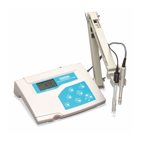
1. Introduction Thank you for purchasing the OAKTON WD-35619-series ® Benchtop meters. These meters are microprocessor controlled, user-friendly and reliable. The large customized LCD allows clear, easy operation. The display has mode annunciators for pH, temperature, mV and ion readings. - Page 4 Rear Panel See Figure 2. The OAKTON ® WD-35619-series meters provide a complete set of input connections for the various accessories commonly used. Listed in the table below are details of the connections that you can make. Connection Function Phono jack connection from the tempera- ture probe for Automatic Temperature Compensation.
- Page 5 Optional Electrode Holder Bottom of meter If you have purchased a benchtop meter with the optional electrode holder, the electrode holder is included in the same box as the meter. Shipping position To attach the electrode holder to the meter: 1.
-
Page 6: Introduction
5. To install the electrode arm, turn meter back to the upright position. — See Figure 6. 6. Line up the hole on the base of the electrode holder arm with the peg on the electrode holder base. Slide the hole securely onto the electrode holder base. -
Page 7: Starting Up
2. Starting Up Back panel connections introduction See Figure 9 . 1. Connect the AC adapter from an AC power source to starting up the power jack (DC). Slide in the adapter jack of the A/C adapter into the meter until it is firmly seated. Voltage is pH calibration set at 9V and the current is at 500 mA, (center positive connector). -
Page 8: Ph Calibration And Measurement
3. pH calibration and measurement For best accuracy calibrate at least a two points using fresh pH buffers. Select calibration buffers with calibra- tion values closest to the measurement range you expect to work in. A three point calibration (USA buffers: 4.01, 7.01, and 10.01 or NIST buffers: 4.01, 6.86 and 9.18) ensures maximum accuracy throughout the measure- ment range. - Page 9 Select pH 4, 7, or 10 buffers in pouches or bottles from the OAKTON standard buffer solutions. Figure 11 1. Press the ON/OFF key. All the LCD segments display for a few seconds.
- Page 10 8. Press the ENTER button. The primary display flashes the calibration value. The calibration point is now stored in the meter. —See Figure 14. READY • If you are performing a one-point calibration, press CAL/MEAS to return to the measurement mode and start taking pH readings.
- Page 11 pH Measurement This meter is capable of taking measurements with automatic or manual temperature compensation. Automatic temperature compensation only occurs when a temperature sensor is plugged into the meter. If there is no temperature MEAS sensor plugged into the meter, the default setting is auto- matically 25°C (if the meter has never been manually set for temperature) or the last manually set value will display.
- Page 12 MEAS body. If the pH electrode had dehydrated, soak it for 30 minutes in OAKTON electrode storage solution or a 2M-4M KCl solution. 2. Press ON to switch on meter. The MEAS annunciator introduction appears on the top center of the LCD.
-
Page 13: Mv Calibration And Measurement
4. mV calibration and measurement mV calibration MEAS The customized LCD display will indicate the following: Display Remarks MEAS Measurement mode is selected. R.mV Unit of measurement °C Unit of temperature measurement Figure 23 Automatic Temperature Compensation introduction (if temperature probe or ”All-in-One“ probe is connected) starting up mV Calibration... -
Page 14: Mv Calibration And Measurement
mV Measurement 1. Make sure you are in the mV measurement mode. Press the MODE key to choose the mV mode. 2. Dip the electrode into the sample. The sensor or glass bulb of the electrode must be completely immersed MEAS into the sample. -
Page 15: Ion Calibration And Measurement (Ion 510 Only)
5. Ion calibration and measurement (Ion 510 only) Ion calibration This instrument is capable of up to three-point ion calibra- tion with a minimum of two-point calibration. Calibration values are 0.10, 1.0, 10.0 or 100.0. All calibration should be one decade apart. For example you may perform three- point calibration to 0.10, 1.0 and 10.0, or two-point calibra- tion to 10.0 and 100.0. - Page 16 8. Rinse off the electrode with deionized water before placing it in the next calibration standard. 9. Allow meter to stabilize in the next calibration standard. Wait for the READY indicator to appear before you press the ENTER key to confirm the second calibration point.
- Page 17 Ion measurement 1. Turn meter ON. Press MODE to select ion MEAS measurement mode. —See Figure 38. 2. Prepare samples as necessary (i.e. add Ionic Strength Adjuster). Sample preparation varies depending on ion type—see your electrode manual for details on the specific electrode that you are using.
-
Page 18: Memory Function
6. Memory functions Memory Input Your meter can store up to 50 sets of data in any combination of values: pH 510 meter: • pH and temperature • mV (or relative mV) and temperature. Ion 510 meter: • pH and temperature •... -
Page 19: Temperature Calibration
7. Temperature calibration Temperature Calibration In this calibration procedure, the ATC probe is attached to the meter and the ATC annunciator displays on MEAS the right hand side of the LCD.—See Figure 45. 1. Dip the temperature probe into a solution of known temperature, such as a temperature bath for a few minutes until the temperature probe stabilizes. -
Page 20: Setup Mode
8. Setup Mode The advanced SETUP mode lets you customize your meter’s preferences and defaults: P1.0: Memory clear (CLr) P2.0: Viewing electrode data (ELE) P3.0: Selecting buffer sets (bUF) P4.0: Reset to factory default settings (rSt) To enter the SETUP mode: 1. - Page 21 P2.0: Viewing electrode data SETUP This program lets you check the electrode parameters for diagnostic purposes. 1. Enter the SETUP mode as described on page 21. The meter automatically goes to program P1.0. 2. Press keys to scroll through the programs until you view ELE in the primary display and P2.0 in the secondary display.
-
Page 22: Setup Mode
P3.0: Selecting buffer sets SETUP This program lets select between two standard calibration buffer sets, depending upon your requirements. The available sets are USA and NIST. 1. Enter the SETUP mode as described on page 21. The meter automatically goes to program P1.0. 2. -
Page 23: Electrode Care
If you do not get good readings, use a measurement different pH electrode to confirm the meter is working properly. If the results are still not satisfactory, consult mV calibration your OAKTON distributor. measurement Electrode Maintenance Ion calibration pH electrodes are susceptible to dirt dehydration and measurement contamination. - Page 24 Thoroughly rinse with de-ionized water. b. General dirt and light oil coatings. introduction Soak the electrode for several hours in OAKTON general purpose electrode cleaning solutions. starting up Rinse in deionized or distilled water.
-
Page 25: Troubleshooting
10. Troubleshooting Error Messages The following table provides a guideline to enable diagnosis of possible problems indicated by the messages generated by the OAKTON WD-35619-series. The table also provides possible solutions to the problems encountered. Error Message Indicates Cause Corrective Action Err. - Page 26 Troubleshooting introduction Problem Cause Solution Nothing is displayed when a. AC outlet power not a. Switch on the power supply starting up the ON/OFF key is selected. switched on. b. AC adapter socket not b. Re-insert Ac adapter socket. inserted properly. pH calibration Unstable reading a.
-
Page 27: Additional Information
7.00 and pH 10.01. Use a 3-point calibration when the sample pH is measurement completely unknown. Use all pH 7.00, pH 4.01 and pH 10.01 calibration solutions. Contact your OAKTON ® distributor for information on pH buffer and calibration solutions. -
Page 28: And Measurement
12. Specifications pH 510 Ion 510 Mode Range 0.0 to 14.0 pH Resolution 0.01 pH Accuracy ±0.01 pH Calibration 1 to 3 points USA: 4.01, 7.00, 10.01 NIST: 4.01, 6.86, 9.18 Range -1999 to 1999 mV introduction Resolution 0.1 mV between ±199.9 mV 1 mV beyond ±199.9 mV Accuracy ±0.2 mV between ±199.9 mV... -
Page 29: Accessories
13. Accessories To order some accessories, contact your OAKTON ® distributor and describe the items listed below. WD-35613-05 ATC probe WD-35615-07 110 VAC adapter WD-35615-08 220 VAC adapter WD-35801-00 OAKTON general purpose pH electrode WD-35805-04 OAKTON general purpose double junction introduction refillable liquid filled pH electrode. -
Page 30: Warranty
14. Warranty OAKTON warrants this meter to be free from significant deviations in material and workmanship for a period of three years from date of purchase. OAKTON warrants this probe to be free from significant deviations in material and workmanship for a period of six months from date of purchase.
Need help?
Do you have a question about the Ion 510 Series and is the answer not in the manual?
Questions and answers