Table of Contents
Advertisement
Quick Links
Advertisement
Table of Contents

Related Manuals for Grace Lunatec V3


Summary of Contents for Grace Lunatec V3
-
Page 1: Owners Manual
Owners Manual Microphone Preamplifi er and A/D Converter Manual Rev E 2434 30th Street, Boulder, CO 80304 USA tel 303.443.7454 fax 303.444.4634 www.gracedesign.com email: info@gracedesign.com Revision D March 2005 © Copyright 2005, Grace Design / Lunatec LLC... - Page 2 V3. Grace Design has been building professional audio products for the recording industry for over ten years. During this time the circuit technology embedded in the lunatec V3 has evolved through a process of extensive listening, testing and refinement.
-
Page 3: Front Panel Controls
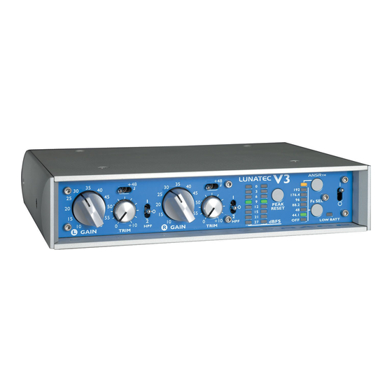
Figure 1. V3 Front Panel FRONT PANEL CONTROLS GAIN CONTROL Each gain control has 11 positions and adjusts the voltage gain from 10dB to 60dB in 5dB steps. TRIM CONTROL The trim control provides 10dB of continuously variable gain trim. In the fully counter-clockwise position the trim is at unity. - Page 4 this switch for 1/2 second. The 1/2 second delay before the sample rate changes is designed to help prevent accidental rate changes while recording. When the “OFF” position is selected, the AD converter module is powered down to reduce power consumption. The sample rate and ANSR™...
-
Page 5: Rear Panel Connections
Figure 2. Rear panel Figure 3. Rear panel with Toslink connector REAR PANEL CONNECTIONS DIGITAL OUTPUT CONNECTORS The V3 has a total of three digital output connectors: two balanced XLR 110Ω outputs and one coaxial 75Ω output. In addition, V3 preamplifiers with the optical out option have a standard Toslink optical output jack. -
Page 6: Analog Audio Connections
CONNECTING THE PREAMPLIFIER ANALOG AUDIO CONNECTIONS Input connections from a microphone are made using female XLR connectors. These are wired with pin 2 positive, pin 3 negative and pin 1 ground. 48V phantom power, if used, is supplied on pins 2 and 3. The V3 can be used as a line level A/D converter. -
Page 7: Operation
A/D converter is on or off. For battery operation it is recommended to use the input power cable supplied by Grace Design or from a reputable battery system supplier. If you choose to supply your own cable, we would recommend the wire be 20 gauge or larger and the 2.1mm DC plug be a Switchcraft S760K locking type connector. -
Page 8: Battery Considerations
USING THE V3 IN M-S MODE In M-S mode the V3 accepts the Mid signal in channel 1 (L) and the Side signal in channel 2 (R). The channel 1 output provides the “sum” of the inputs and the channel 2 output provides the “difference”... - Page 9 DC SUPPLY VOLTAGE JUMPERS Jumpers J26 and J27 select the operation Voltage to be 6 or 12 Volts DC. These jumpers should be moved ONLY by a qualified technician. Consult the factory for voltage change information. AD MODULE ADJ6 GRACE DESIGN ADJ7 P300 REV A FRONT PANEL Figure 5. V3 INTERNAL JUMPER LOCATIONS...
-
Page 10: Specifications
SPECIFICATIONS MICROPHONE AMPLIFIER SECTION Frequency Response @ 60dB gain -3dB 6Hz-250kHz THD+N @ 20dB gain +20dBu out 0.0011% @ 40dB gain +20dBu out 0.0011% @ 60dB gain +20dBu out 0.0046% Intermodulation Distortion @ 40dB gain +20dBu out SMPTE/DIN 4:1 50Hz,7k <.0045% Noise - Referred To Input @ 60dB gain 50 Ohm source... - Page 11 Using a cable without this jumper for the regulated output will not work, as this battery output will be shutoff. If you have any further questions, please contact us at 303-443-7454). Have fun! -The Grace Design Team page 11...
-
Page 12: Warranty Information
Warranty Information Grace Design warrants all of our products to be free of defective parts and workmanship for a period of five years. This warranty period begins at the original date of purchase and is transferable to any person who may subsequently purchase the product during this time.
Need help?
Do you have a question about the Lunatec V3 and is the answer not in the manual?
Questions and answers