
Related Manuals for Grace Grace 901


Summary of Contents for Grace Grace 901
-
Page 1: Headphone Amplifier
Model 901 HEADPHONE AMPLIFIER OWNERS MANUAL PO Box 204 Boulder, CO 80306 tel: 303.443.7454 fax: 303.444.4634 email: info@gracedesign.com web: www.gracedesign.com Revision A November, 2001 © Copyright 2001, Lunatec LLC... - Page 2 Thank you for purchasing the Model 901 headphone amplifier. It is designed to be completely reliable and easy to use. However, we ask that you take the time to familiarize yourself with some of the more important operation instructions in this manual to avoid most common user problems. The Model 901 amplifier is an ultra high fidelity monitoring device.
-
Page 3: Input Select
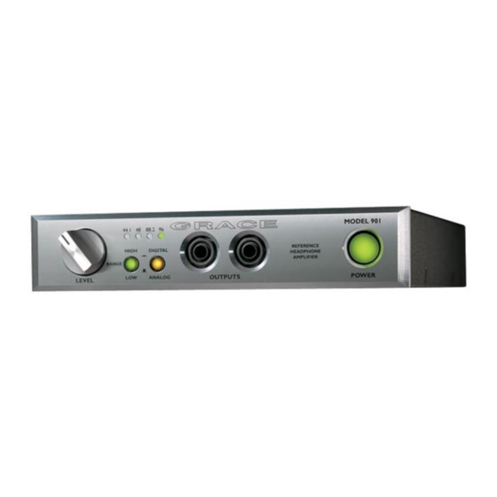
SAMPLE RATE POWER SWITCH LEVEL CONTROL INDICATOR GAIN RANGE INPUT SELECT OUTPUT JACK FRONT PANEL CONTROLS LEVEL CONTROL The 901 level control is assembled with an ultra precision 24 position gold contact switch. Using low inductance surface mount metal film resistors this switch is the ultimate attenuator for sonic fidelity and level accuracy. - Page 4 INPUT SELECT This switch selects the input source. With the switch out the analog inputs are selected. XLR balanced and RCA unbalanced connectors are provided on the rear panel. When the INPUT SELECT switch is depressed the digital inputs are selected. AES3, S/PDIF and optical inputs are provided on the rear panel.
-
Page 5: Rear Panel Controls
REAR PANEL CONTROLS AC INLET The 901 accommodates a standard IEC power cable. The IEC inlet contains a built in RFI filter. LINE VOLTAGE SELECTOR To change the line voltage use a small screwdriver to pry open the voltage select door. Carefully remove the voltage select cam and insert with the desired voltage showing. -
Page 6: Output Impedance
ANALOG INPUTS The 901 provides both balanced and unbalanced inputs. Input connections are made using the female XLR connector on the rear panel. These connectors are wired with pin 2 positive, pin 3 negative and pin 1 ground. The unbalanced phono type jacks are wired in parallel with pin 2 of the XLR balanced jacks. - Page 7 NOISE FLOOR 0dB gain, 22-22kHz -95dBu 0dB gain, A-weighted -102dBu POWER REQUIREMENTS 115VAC .16A 230VAC .08A...
Need help?
Do you have a question about the Grace 901 and is the answer not in the manual?
Questions and answers