Table of Contents
Advertisement
Quick Links
Download this manual
See also:
Owner's Manual
Advertisement
Table of Contents

Summary of Contents for Grace 101
-
Page 1: Owners Manual
model model MICROPHONE PREAMPLIFIER OWNERS MANUAL PO Box 204 Boulder, CO. 80306 voice: 303.443.7454 fax: 303.444.4634 email: info@gracedesign.com web: www.gracedesign.com Revision B April, 2001 © Copyright 2000, Lunatec LLC HI Z 1OdB 6OdB -1OdB GAIN TRIM POWER... - Page 2 Regardless of what audio sources you plan to record, the Model 101 will faithfully serve as an invisible link between your microphone or instrument and recording device. We hope it helps you achieve a new level of excellence in your audio recordings.
- Page 3 MODEL 101 FEATURES Fully balanced transformerless mic input and high impedance instrument input Balanced XLR and 1/4" TRS outputs Ultra clean 48 Volt phantom power 11 position precision silver contact rotary gain switch High quality conductive plastic 10dB output attenuator...
-
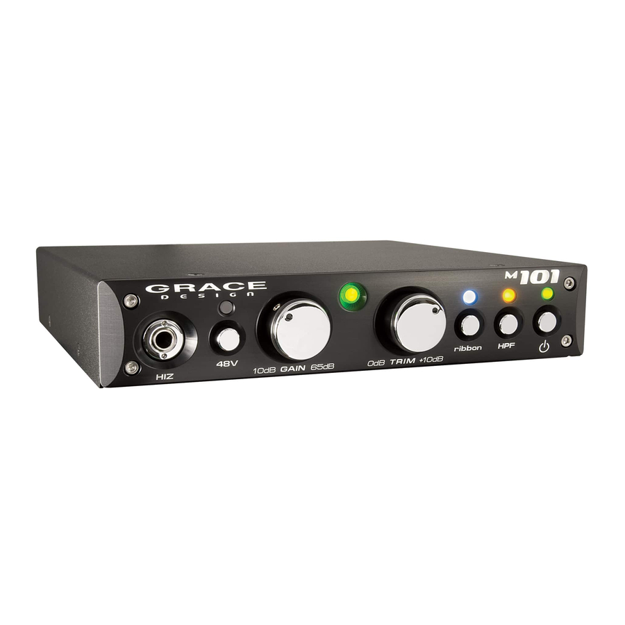
Page 4: Front Panel Controls
–10dB to 40dB in 5dB steps. NOTE: If you ordered the high gain version of the 101 for use with ribbon microphones, the gain range of your unit on the microphone input is 20dB to 70dB in 5dB steps and the gain range of the instrument input is 0dB to 50dB in 5 dB steps. -
Page 5: Audio Connections
CONNECTING THE PREAMPLIFIER AUDIO CONNECTIONS l Microphone input connections are made using the female XLR connector on the rear panel. This connector is wired with pin 2 positive, pin 3 negative and pin 1 ground. 48V phantom power, if used, is supplied on pins 2 and 3. l Instrument or line input connections are made using the ¼”... -
Page 6: Power Supply Connections
TRS UNBALANCED OUTPUT CABLE TERMINATION POWER SUPPLY CONNECTIONS A 2.1mm jack is used for the DC power input of the 101. The polarity of the jack is positive in the center and ground on the outside. Included with your Model 101 is an AC adapter rated for 6VDC @ 800mA. -
Page 7: Operation
OPERATION SETTING THE GAIN l Turn the gain control fully counter-clockwise, turn the trim control fully clockwise and check that the +48V phantom power is off. l Connect the microphone to the preamplifier and then turn on the phantom power switch on if required. l When sending a signal to a recorder that has fixed input levels, simply increase the gain until the optimum recording level is reached. - Page 8 Model 101 Specifications GAIN RANGE Mic input 5dB steps Mic input 5dB steps High gain version Hi-Z input 5dB steps Hi-Z input 5dB steps High gain verzsion Output trim attenuator THD+N @20dB Gain +20dBu out @40dB Gain +20dBu out @60dB Gain +20dBu out...
- Page 9 75Hz HIGH PASS FILTER RESPONSE -100 Phase response @10dB gain. 50 Ohm source, 100K Ohm load, HPF Off FFT SPECTRUM ANALYSIS FFT @40dB gain, +20dBu out PHASE vs FREQUENCY...


Need help?
Do you have a question about the 101 and is the answer not in the manual?
Questions and answers