Summary of Contents for Grace LUNATEC V2
-
Page 1: Owners Manual
OWNERS MANUAL LUNATEC V2 MICROPHONE PREAMPLIFIER PO Box 204 Boulder, CO. 80306 voice: 303.443.7454 fax: 303.444.4634 email: info@gracedesign.com Revision A December, 1998 © Copyright 1998, Lunatec LLC... - Page 2 Lunatec V2 has evolved through a process of extensive listening, testing and refinement. Regardless of what audio sources you plan to record, the Lunatec V2 will faithfully serve as an invisible link between your microphone and recorder device. We hope it helps you achieve a new level of excellence in your audio recordings.
-
Page 3: Front Panel Controls
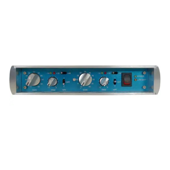
FRONT PANEL CONTROLS GAIN CONTROL Each gain control has 11 positions and adjusts the voltage gain from 10dB to 60dB in 5dB steps. TRIM CONTROL The trim control provides 10dB of continuously variable output attenuation. In the fully clockwise position the trim is at unity (no attenuation). In the fully counter-clockwise position the trim is at -10dB. -
Page 4: Audio Connections
CONNECTING THE PREAMPLIFIER AUDIO CONNECTIONS Input connections are made using female XLR connectors. These are wired with pin 2 positive, pin 3 negative and pin 1 ground. 48V phantom power, if used, is supplied on pins 2 and 3. Output connections are made using male XLR connectors or RCA phono jacks. The XLR connectors are wired with pin 2 positive, pin 3 negative and pin 1 ground. -
Page 5: Operation
OPERATION SETTING THE GAIN Turn the gain control fully counter-clockwise, turn the trim control fully clockwise and check that the +48V phantom power is off. Connect the microphone to the preamplifier and then turn the phantom power switch on if required. When sending a signal to a tape recorder that has fixed input levels, simply increase the gain until the optimum recording level is reached. -
Page 6: Battery Considerations
12Volt V2 to run warm to the touch. JUMPER SETTINGS In addition to the front panel controls, the Lunatec V2 has several options that can be selected with internal jumpers. Before making any changes to the internal jumpers always disconnect any power source from the V2, switch both +48 switches to the on position and wait for 1 minute before removing the top cover. - Page 7 Figure 3. Circuit Board Jumper Locations SN #V054 and below Figure 4. Circuit Board Jumper Locations SN #V055 and above...
-
Page 8: Specifications
SPECIFICATIONS @60dB gain FREQUENCY RESPONSE +/- 3dB @60dB gain: THD+N +20dBu out @20dB gain +20dBu out @40dB gain +20dBu out @60dB gain INTERMODULATION DISTORTION @40dB gain +25dBu out NOISE - REFERRED TO INPUT @60dB gain 50 Ohm source PHASE DEVIATION 50-20Khz CROSSTALK Either Channel...


Need help?
Do you have a question about the LUNATEC V2 and is the answer not in the manual?
Questions and answers