
Related Manuals for Grace ALiX


Summary of Contents for Grace ALiX
- Page 1 Instrument Preamplifier / EQ / DI Owner’s Manual Rev. C Grace Design, 4689 Ute Highway, Lyons, CO 80503 303.823.8100 / info@gracedesign.com www.gracedesign.com...
-
Page 2: Table Of Contents
1 Welcome Like its big brother FELiX, the ALiX you hold in your hand is It is our sincere hope that our gear helps you do better work. designed to make you sound better, play better and have more You are why we do this. Please drop us a line or a message and fun in the process. -
Page 3: Safety Marking Symbols
Powerful, independent EQ – hi and low shelving and full • Universal 100-240 AC power supply with standard IEC parametric midrange cable – no wall wart - take ALiX anywhere in the world! • Mid frequency control has two ranges 70-880Hz / 670 - •... -
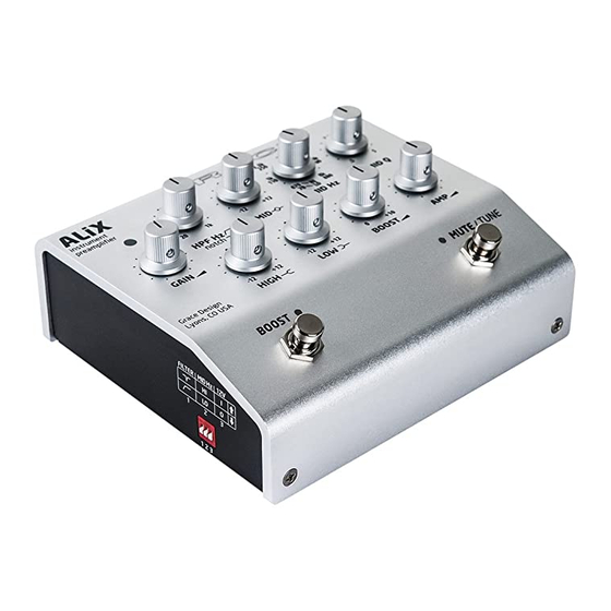
Page 4: Top Panel Controls And Features
5 Top Panel Controls and Features Signal / clip LED indicator Gain control High Pass / Notch filter frequency select Parametric Midrange cut and boost Parametric Midrange frequency select Parametric Midrange Q factor BOOST footswitch Low frequency shelving cut and boost High frequency shelving cut and boost 10. -
Page 5: Back Panel Controls And Features
6 Back Panel Controls and Features Tuner Output Universal input100-240VAC power supply input module Instrument line input 9VDC @ 500mA auxiliary power output Effects Insert Ground lift switch 10. Input impedance select DI output 11. Phase reverse switch DI output line / mic level select Amp Output 7 Side Panel Controls and Features DIP switch controls:... -
Page 6: Connecting Alix To Stuff
8.5 DI OUTPUT This is for connecting any instrument with a pickup, electret mic or line out jack to ALIX. The connector is a standard 1/4” This outputs is a balanced and transformer isolated, for sending jack wired tip signal, sleeve ground. The ring is used only for signal to a front of house, monitor console, or any mixer or 12V mic power if needed. -
Page 7: Filtering And Eq
Phase Reverse HPF might be your first stop to try to control those problems. ALiX has a phase reverse switch, located on the rear panel, top Notch: A notch filter is a very sharp and deep cut of a specific right (facing the rearpanel), directly above the input impedance frequency. -
Page 8: Output Controls
HIGH SHELF EQ 9.6 SIDE PANEL CONTROLS +12dB ALiX has a lot going on, more than we could fit on the rear and top panels alone. So there are a few features to be familiar with -12dB on the side panel. -
Page 9: Diagrams
Normally these microphones will present at the input of ALiX. It is always best to make your input contain very small integrated preamps which require a voltage connections before applying power at the DIP switch, and power to power. -
Page 10: Block Diagram
10.2 BLOCK DIAGRAM... -
Page 11: Connection Diagram
10.3 CONNECTION DIAGRAM... -
Page 12: Adjusting Internal Jumpers
IMPORTANT: Before you do anything, disconnect ALiX from the AC power, disconnect all cables and place ALiX on a flat stable surface with good lighting. figure 1 Did you completely disconnect the 1. -
Page 13: Internal Jumper Locations
10.5 INTERNAL JUMPER LOCATIONS J10 configures the LOW EQ corner frequency. It is set to LF1 at the factory (125Hz corner frequency) with the jumper only connected to one pin. To set to LF2 (250Hz corner frequency), simply push the jumper down onto both pins, so they are connected by the jumper. -
Page 14: Specifications
11 Specifications GAIN RANGE (Instrument Input to DI Output) DI Output, Level: Line -2dB - 36dB Amp Output 0dB-39dB Boost 0dB-10dB THD+N 22Hz-22kHz BW 1kHz @ 0dB Gain +10dBu out <0.0070% 1kHz @ 20dB Gain +10dBu out <0.0045% 1kHz @ 36dB Gain +10dBu out <0.0080% INTERMODULATION DISTORTION - SMPTE/DIN 4:1 7kHz/50Hz @ 40dB Gain +10dBu out ... -
Page 15: Cleaning And Maintenance
In no event will Grace Design be liable for lost profits or any other incidental, consequential or Exemplary damages, even if Grace Design is aware of the possibility of such damages. In no event will Grace Design’s liability exceed the purchase price of the product. -
Page 16: Manual Revisions
14 Manual Revisions Revision Page Change Date Initials Initial release 06/08/2016 3,6,14 Added info about 9V 500mA DC power output jack 07/08/2016 3,6,14 Corrected input impedance values 7/11/2016 Corrected wrong jumper placement info 11/16/2016...
Need help?
Do you have a question about the ALiX and is the answer not in the manual?
Questions and answers