Dell PowerVault NX3100 Hardware Owner's Manual
Powervault nx3100 systems
Hide thumbs
Also See for PowerVault NX3100:
- Getting started with (125 pages) ,
- Administrator's manual (50 pages) ,
- Manual (84 pages)
Table of Contents
Advertisement
Advertisement
Table of Contents
Troubleshooting

Related Manuals for Dell PowerVault NX3100


Summary of Contents for Dell PowerVault NX3100
- Page 1 Dell™ PowerVault™ NX3100 Systems Hardware Owner’s Manual...
- Page 2 Reproduction of these materials in any manner whatsoever without the written permission of Dell Inc. is strictly forbidden. Trademarks used in this text: Dell, the DELL logo, and PowerVault are trademarks of Dell Inc.; Microsoft, Windows, Windows Server, and MS-DOS are either trademarks or registered trademarks of Microsoft Corporation in the United States and/or other countries.
-
Page 3: Table Of Contents
Contents About Your System ......Accessing System Features During Startup ..Front-Panel Features and Indicators . - Page 4 ... Entering the System Setup Program ... Responding to Error Messages Using the System Setup ....Program Navigation Keys .
- Page 5 Installing System Components ......Recommended Tools ....Inside the System .
- Page 6 ....Replacing a Cooling Fan ..... Power Supplies .
- Page 7 ..Removing a VFlash Media Card ....Internal USB Memory Key ......Processors .
- Page 8 ..Troubleshooting External Connections ..Troubleshooting the Video Subsystem ... . Troubleshooting a USB Device .
- Page 9 ......... . . Contacting Dell Index .
- Page 10 Contents...
-
Page 11: About Your System
The controller allows you to access utilities such as embedded system diagnostics. For information on Lifecycle Controller or any of the Lifecycle Controller software components, see the Lifecycle Controller documentation on the Dell Support website at support.dell.com/manuals. <F11> Enters the BIOS Boot Manager or the Unified Extensible Firmware Interface (UEFI) Boot Manager, depending on the system’s boot... -
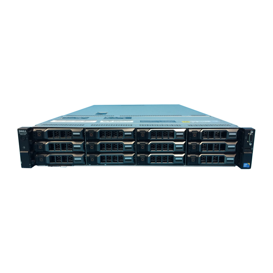
Page 12: Front-Panel Features And Indicators
Front-Panel Features and Indicators Figure 1-1. Front-Panel Features and Indicators Item Indicator, Button, Icon Description or Connector LED panel The LED panel has four diagnostic indicator lights that display error codes during system startup. See "Diagnostic Lights" on page 21. About Your System... - Page 13 Item Indicator, Button, Icon Description or Connector Power-on indicator/ The power-on indicator lights power button when the system power is on. The power button controls the DC power supply output to the system. When the optional system bezel is installed, the power button is not accessible.
- Page 14 Item Indicator, Button, Icon Description or Connector System identification A slide-out panel for system information panel including the Express Service tag, embedded NIC MAC address, and iDRAC6 Enterprise card MAC address. USB connector Connect USB devices to the system. The ports are USB 2.0-compliant. Video connector Connects a monitor to the system.
-
Page 15: Hard-Drive Indicator Patterns
Hard-Drive Indicator Patterns Figure 1-2. Hard-Drive Indicators hard-drive activity indicator 2 hard-drive status indicator (green) (green and amber) Drive-Status Indicator Pattern Condition Blinks green two times per second Identify drive/preparing for removal Drive ready for insertion or removal NOTE: The drive status indicator remains off until all hard drives are initialized after system power is applied. -
Page 16: Back-Panel Features And Indicators
Drive-Status Indicator Pattern Condition Blinks amber four times per second Drive failed Blinks green slowly Drive rebuilding Steady green Drive online Blinks green three seconds, off three Rebuild aborted seconds, amber three seconds, and off three seconds. Back-Panel Features and Indicators Figure 1-3. - Page 17 Item Indicator, Button, or Icon Description Connector iDRAC6 Enterprise Dedicated management port for the port (optional) optional iDRAC6 Enterprise card. VFlash media slot Connects an external SD memory card (optional) for the optional iDRAC6 Enterprise card. USB connectors (2) Connect USB devices to the system. The ports are USB 2.0-compliant.
-
Page 18: Guidelines For Connecting Optional External Devices
Item Indicator, Button, or Icon Description Connector System status Lights blue during normal indicator system operation. Both the systems management software and the identification buttons located on the front and back of the system can cause the indicator to flash blue to identify a particular system. -
Page 19: Nic Indicator Codes
NIC Indicator Codes Figure 1-4. NIC Indicators link indicator activity indicator Indicator Indicator Code Link and activity The NIC is not connected to the network. indicators are off Link indicator is green The NIC is connected to a valid network link at 1000 Mbps. - Page 20 • Amber—Indicates a problem with the power supply. • Alternating green and amber—When hot-adding a power supply, this indicates that the power supply is mismatched with the other power supply. Replace the power supply that has the flashing indicator with a power supply that matches the capacity of the other installed power supply.
-
Page 21: Diagnostic Lights
Diagnostic Lights The four diagnostic indicator lights on the system front panel display error codes during system startup. Table 1-1 lists the causes and possible corrective actions associated with these codes. A highlighted circle indicates the light is on; a non-highlighted circle indicates the light is off. Table 1-1. - Page 22 Memory" on page 137. Possible system board See "Getting Help" on page 157. resource and/or system board hardware failure. Possible system resource See "Contacting Dell" on configuration error. page 157. Other failure. Ensure that the optical drive, and hard drives are properly connected.
-
Page 23: System Messages
System Messages System messages appear on the screen to notify you of a possible problem with the system. NOTE: If you receive a system message not listed in the table, check the documentation for the application that is running or the operating system's documentation for an explanation of the message and recommended action. - Page 24 Message Causes Corrective Actions The optional iDRAC6 is not Wait for the system Alert! iDRAC6 not responding to BIOS to reboot. responding. communication either Rebooting. because it is not functioning properly or has not completed initialization. The system reboots. The optional iDRAC6 Remove AC power to the Alert! iDRAC6 not has hung.
- Page 25 Message Causes Corrective Actions The system configuration If any system components Alert! Power of processor(s), were just upgraded, required exceeds memory modules, return the system to the PSU wattage. and expansion cards may previous configuration. Check PSU and not be supported by the If the system boots without system power supplies.
- Page 26 Message Causes Corrective Actions Remote BIOS update Retry the BIOS update. BIOS Update attempt failed. If problem persists, Attempt Failed! see "Getting Help" on page 157. NVRAM_CLR jumper is Move the NVRAM_CLR Caution! installed in the clear setting. jumper to the default NVRAM_CLR jumper CMOS has been cleared.
- Page 27 Message Causes Corrective Actions Mismatched processors have Ensure that all processors CPUs with been installed in the system. have the same cache size, different cache number of cores and logical sizes detected. processors, and power rating. CPUs with Ensure that the processors different core are properly installed.
- Page 28 Message Causes Corrective Actions Invalid memory Ensure that the memory DIMM configuration on a modules are installed in a configuration on dual-processor system. valid configuration. each CPU should The memory module See "General Memory match. configuration for each Module processor must be identical. Installation Guidelines"...
- Page 29 Message Causes Corrective Actions Overcurrent detected at the See "Getting Help" on Keyboard fuse has keyboard connector. page 157. failed. The USB ports are disabled Power down and restart the Local keyboard in the system BIOS. system from the power may not work button, and then enter the because all user...
- Page 30 Message Causes Corrective Actions The memory frequency may If not an intentional setting, Memory set to be intentionally set lower for check any other system minimum power conservation. messages for possible causes. frequency. The current memory Ensure that your memory configuration may support configuration supports the only the minimum frequency.
- Page 31 Message Causes Corrective Actions Faulty or missing optical Use a bootable USB key, No boot device drive subsystem, hard drive, optical drive, or hard drive. available. or hard drive subsystem, or If the problem persists, see no bootable USB key "Troubleshooting a USB installed.
- Page 32 Message Causes Corrective Actions Error encountered in Install the NVRAM_CLR Plug & Play initializing PCIe device; jumper in the clear position Configuration faulty system board. (pins 1 and 3) and reboot the Error. system. See Figure 6-1 for jumper location. If the problem persists, see "Troubleshooting Expansion Cards"...
- Page 33 Message Causes Corrective Actions Faulty hard drive, USB Replace the USB medium or Sector not found. device, or USB medium. device. Ensure that the USB Seek error. or SAS backplane cables are Seek operation properly connected. See failed. "Troubleshooting a USB Device"...
- Page 34 Message Causes Corrective Actions Invalid memory Ensure that the memory The following configuration. The specified modules are installed in a DIMMs should memory modules do not valid configuration. match match in size, number of See "General Memory geometry: ranks, or number of Module x , x , ...
- Page 35 Enterprise card flash memory Restore the flash memory or BMC SPI flash may be using the latest version on corrupted. support.dell.com. See the Integrated Dell™ Remote Access Controller 6 (iDRAC6) User Guide for instructions on performing a field replacement of the flash memory.
- Page 36 Message Causes Corrective Actions Improperly seated memory Reseat the memory modules. Unexpected modules or faulty See "Troubleshooting interrupt in keyboard/mouse System Memory" on protected mode. controller chip. page 137. If the problem persists, see "Getting Help" on page 157. Processor(s) is not supported Install a supported processor Unsupported CPU by the system.
- Page 37 Message Causes Corrective Actions The memory configuration is Reconfigure the memory for Unused memory not optimal for Advanced Advanced ECC Memory detected. DIMM’s ECC Memory Mode. Mode, or change the installed in the Modules in the specified memory mode to Optimized following slot slots are unused.
- Page 38 Message Causes Corrective Actions The system configuration of If any system components Warning! Power processor(s), memory were just upgraded, required exceeds modules, and expansion return the system to the PSU wattage. cards may not be supported previous configuration. If Check PSU and by the power supplies.
-
Page 39: Warning Messages
Drive" on page 140. NOTE: For the full name of an abbreviation or acronym used in this table, see the Glossary at support.dell.com. Warning Messages A warning message alerts you to a possible problem and prompts you to respond before the system continues a task. Warning messages usually interrupt the task and require you to respond by typing y (yes) or n (no). -
Page 40: Other Information You May Need
Lifecycle Controller User Guide the controller, configuring hardware and firmware, and deploying the operating system. NOTE: Always check for updates on support.dell.com/manuals and read the updates first because they often supersede information in other documents. About Your System... -
Page 41: Using The System Setup Program And Uefi Boot Manager
Using the System Setup Program and UEFI Boot Manager The System Setup program is the BIOS program that enables you to manage your system hardware and specify BIOS-level options. From the System Setup program, you can: • Change the NVRAM settings after you add or remove hardware •... -
Page 42: Entering The System Setup Program
Entering the System Setup Program 1 Turn on or restart your system. 2 Press <F2> after you see the following message: <F2> = System Setup NOTE: The system does not respond until the USB keyboard is active. If your operating system begins to load before you press <F2>, allow the system to finish booting, and then restart your system and try again. -
Page 43: System Setup Options
System Setup Options Main Screen Figure 2-1. Main System Setup Program Screen NOTE: The options for the System Setup program change based on the system configuration. NOTE: The System Setup program defaults are listed under their respective options in the following sections, where applicable. Option Description System Time... - Page 44 Option Description SATA Settings See "SATA Settings Screen (Optional)" on page 47. (Optional) Boot Settings See "Boot Settings Screen" on page 47. Integrated Devices See "Integrated Devices Screen" on page 48. PCI IRQ Displays a screen to change the IRQ assigned to each of the Assignment integrated devices on the PCI bus, and any installed expansion card that requires an IRQ.
-
Page 45: Memory Settings Screen
Memory Settings Screen Option Description System Memory Size Displays the system memory size. System Memory Type Displays the system memory type. System Memory Speed Displays the system memory speed. Video Memory Displays the video memory size. System Memory Testing Specifies whether system memory tests are run at system (Enabled default) boot. - Page 46 Option Description Logical Processor Each processor core supports up to two logical (Enabled default) processors. If this field is set to Enabled, the BIOS reports both logical processors. If set to Disabled, only one logical processor is monitored by the BIOS. Virtualization Technology Enabled permits virtualization software to use the (Disabled default)
-
Page 47: Sata Settings Screen (Optional)
SATA Settings Screen (Optional) Option Description SATA controller ATA Mode enables the integrated SATA controller. RAID (ATA Mode default) Mode enables the integrated SATA controller to RAID mode. Off disables the controller. NOTE: When set to RAID mode, all ports are set to OFF. Port A Auto enables BIOS support for the device attached to (Auto default) -
Page 48: Integrated Devices Screen
Option Description Hard-Disk Drive Determines the order in which the BIOS attempts to Sequence boot from hard drives in the system during system startup. USB Flash Drive Determines the emulation type for a USB flash drive. Emulation Type Hard disk allows the USB flash drive to act as a hard (Auto default) drive. -
Page 49: Pci Irq Assignments Screen
Option Description OS Watchdog Timer Sets a timer to monitor the operating system for activity, (Disabled default) and aids in recovery if the system stops responding. When Enabled, the operating system is allowed to initialize the timer. When Disabled, the timer is not initialized. - Page 50 Option Description Serial Port Address Sets the serial port addresses for the two serial devices. (Serial Device 1=COM1, NOTE: Only Serial Device 2 can be used for Serial Over Serial Device 2=COM2 LAN (SOL). To use console redirection by SOL, configure default) the same port address for console redirection and the serial device.
-
Page 51: Power Management Screen
Power Management Screen Option Description Power Options are OS Control, Active Power Controller, Custom, Management or Maximum Performance. For all but the Custom setting, the (Active Power BIOS pre-configures the power settings on this screen as follows: Controller • OS Control sets the CPU power to OS DBPM, the fan power to default) Minimum Power, and the memory power to Maximum Performance. -
Page 52: System Security Screen
System Security Screen Option Description System Password Displays the current status of the password security feature and allows a new system password assignment and verification. NOTE: See "Using the System Password" on page 56 for more information. Setup Password Restricts access to the System Setup program by using a setup password. - Page 53 Option Description CAUTION: TPM Clear Clearing the TPM loses all encryption (No default) keys in the TPM. This option prevents booting to the operating system and results in data loss if the encryption keys cannot be restored. Back up the TPM keys prior to enabling this option.
-
Page 54: Exit Screen
Exit Screen Press <Esc> to exit the System Setup program; the Exit screen displays: • Save Changes and Exit • Discard Changes and Exit • Return to Setup Entering the UEFI Boot Manager NOTE: Operating systems must be 64-bit UEFI-compatible (for example, ®... -
Page 55: Uefi Boot Manager Screen
Keys Action <Esc> Refreshes the UEFI Boot Manager screen (page one) or returns to the previous screen. <F1> Displays the UEFI Boot Manager help file. UEFI Boot Manager Screen Option Description Continue The system attempts to boot to devices starting with the first item in the boot order. -
Page 56: System Utilities Screen
System Utilities Screen Option Description System Setup Accesses the System Setup program without rebooting. System Services Restarts the system and accesses the controller, which enables you to run utilities such as system diagnostics. BIOS Boot Manager Accesses the BIOS-level boot options list without rebooting. - Page 57 When a system password is not assigned and the password jumper on the system board is in the enabled position, System Password is Not Enabled and Password Status is Unlocked. To assign a system password: 1 Verify that Password Status is Unlocked. 2 Highlight the System Password option and press <Enter>.
-
Page 58: Using The Setup Password
When Password Status is Locked, you must type the password and press <Enter> when prompted at reboot. If an incorrect system password is entered, the system displays a message and prompts you to re-enter your password. You have three attempts to enter the correct password. - Page 59 NOTE: The setup password can be the same as the system password. If the two passwords are different, the setup password can be used as an alternate system password. The system password cannot be used in place of the setup password. You can use up to 32 characters in your password.
-
Page 60: Embedded System Management
For more information about setting up the controller, configuring hardware and firmware, and deploying the operating system, see the Lifecycle Controller on the Dell Support website at support.dell.com/manuals. User Guide iDRAC Configuration Utility The iDRAC Configuration Utility is a pre-boot configuration environment that allows you to view and set parameters for the iDRAC6 and for the managed server. -
Page 61: Entering The Idrac Configuration Utility
• Change the administrative username and password and manage user privileges. • View System Event Log (SEL) messages or clear messages from the log. For additional information on using iDRAC6, see the documentation for iDRAC6 and systems management applications. Entering the iDRAC Configuration Utility 1 Turn on or restart your system. - Page 62 Using the System Setup Program and UEFI Boot Manager...
-
Page 63: Installing System Components
Damage due to servicing that is not authorized by Dell is not covered by your warranty. Read and follow the safety instructions that came with the product. - Page 64 Figure 3-1. Inside the System cooling fan internal hard drives (2) expansion-card riser power supply bays (2) cooling shroud heat sink/processor (2) memory modules (8) system cooling fans (4) SAS backplane hard drives (12) Installing System Components...
-
Page 65: Front Bezel (Optional)
Front Bezel (Optional) Removing the Front Bezel 1 Using the system key, unlock the bezel. 2 Lift the release latch next to the key lock. 3 Rotate the left end of the bezel away from the front panel. 4 Unhook the right end of the bezel and pull the bezel away from the system. -
Page 66: Installing The Front Bezel
You should only perform troubleshooting and simple repairs as authorized in your product documentation, or as directed by the online or telephone service and support team. Damage due to servicing that is not authorized by Dell is not covered by your warranty. Read and follow the safety instructions that came with the product. -
Page 67: Closing The System
Figure 3-3. Removing and Replacing the System Cover system cover latch latch release lock Closing the System 1 Lift the latch on the system cover. 2 Place the cover onto the chassis and offset it slightly back so that the two hooks on the back edge of the cover fit the corresponding tabs on the back edge of the chassis. -
Page 68: Cooling Shroud
You should only perform troubleshooting and simple repairs as authorized in your product documentation, or as directed by the online or telephone service and support team. Damage due to servicing that is not authorized by Dell is not covered by your warranty. Read and follow the safety instructions that came with the product. -
Page 69: Installing The Cooling Shroud
Damage due to servicing that is not authorized by Dell is not covered by your warranty. Read and follow the safety instructions that came with the product. -
Page 70: Installing A Hard-Drive Blank
Figure 3-5. Removing and Installing a Hard-Drive Blank hard-drive blank release lever Installing a Hard-Drive Blank Align the hard-drive blank with the drive bay and insert the blank into the drive bay until the release lever clicks into place. See Figure 3-5. Removing a Hot-Swap Hard Drive 1 If applicable, remove the front bezel. -
Page 71: Installing A Hot-Swap Hard Drive
Figure 3-6. Removing and Installing a Hot-Swap Hard Drive release button hard-drive carrier handle Installing a Hot-Swap Hard Drive CAUTION: Use only hard drives that have been tested and approved for use with the SAS/SATA backplane. CAUTION: When installing a hard drive, ensure that the adjacent drives are fully installed. -
Page 72: Removing A Hard Drive From A Hard-Drive Carrier
4 With the lever on the hard drive carrier open, slide the hard drive into the drive bay until the carrier contacts the backplane. See Figure 3-6. 5 Close the handle to lock the drive in place. Removing a Hard Drive From a Hard-Drive Carrier Remove the screws from the slide rails on the hard-drive carrier and separate the hard drive from the carrier. -
Page 73: Installing A Hard Drive Into A Hard-Drive Carrier
You should only perform troubleshooting and simple repairs as authorized in your product documentation, or as directed by the online or telephone service and support team. Damage due to servicing that is not authorized by Dell is not covered by your warranty. Read and follow the safety instructions that came with the product. - Page 74 Figure 3-8. Installing and Removing an Internal Hard Drive Bay internal hard drives (2) release latch internal hard drive bay support bracket Installing System Components...
-
Page 75: Installing An Internal Hard Drive Bay
You should only perform troubleshooting and simple repairs as authorized in your product documentation, or as directed by the online or telephone service and support team. Damage due to servicing that is not authorized by Dell is not covered by your warranty. Read and follow the safety instructions that came with the product. -
Page 76: Removing An Internal Hard Drive From The Internal Hard-Drive Bay
(4) internal hard drive *Screws are supplied along with the hard drives ordered from Dell. Installing a Hard Drive Into a Hard-Drive Bay 1 Insert the hard drive into the internal hard-drive bay with the connector end of the drive at the back, until it is flush with the back of the hard-drive bay. -
Page 77: Cooling Fans
You should only perform troubleshooting and simple repairs as authorized in your product documentation, or as directed by the online or telephone service and support team. Damage due to servicing that is not authorized by Dell is not covered by your warranty. Read and follow the safety instructions that came with the product. - Page 78 Figure 3-10. Removing and Installing a Fan fans (5) release tab fan cable Installing System Components...
-
Page 79: Replacing A Cooling Fan
Damage due to servicing that is not authorized by Dell is not covered by your warranty. Read and follow the safety instructions that came with the product. -
Page 80: Removing A Redundant Power Supply
You should only perform troubleshooting and simple repairs as authorized in your product documentation, or as directed by the online or telephone service and support team. Damage due to servicing that is not authorized by Dell is not covered by your warranty. Read and follow the safety instructions that came with the product. -
Page 81: Installing A Redundant Power Supply
Figure 3-11. Removing and Installing a Redundant Power Supply power supply power supply handle velcro strap release latch Installing a Redundant Power Supply 1 Verify that both power supplies are of the same type and have the same maximum output power. NOTE: The maximum output power (shown in watts) is listed on the power supply label. -
Page 82: Removing The Power Supply Blank
NOTE: When installing, hot-swapping, or hot-adding a new power supply in a system with two power supplies, allow several seconds for the system to recognize the power supply and determine its status. The power-supply status indicator turns green to signify that the power supply is functioning properly (see Figure 1-5). Removing the Power Supply Blank If you are installing a second power supply, remove the power supply blank in bay PS2 by pulling outward on the blank. -
Page 83: General Memory Module Installation Guidelines
General Memory Module Installation Guidelines To ensure optimal performance of your system, observe the following general guidelines when configuring your system memory. NOTE: Memory configurations that fail to observe these guidelines can prevent your system from starting and producing any video output. •... -
Page 84: Mode-Specific Guidelines
Mode-Specific Guidelines Three memory channels are allocated to each processor. The number of channels used and the allowable configurations depend on the memory mode selected. Advanced ECC (Lockstep) Mode Support In this configuration, the two channels closest to the processor are combined to form one 128-bit channel. - Page 85 Table 3-1. Sample RDIMM Single- and Dual-Rank Memory Configurations (Per Processor) Memory Single Processor Dual Processor Memory Sockets Memory Module Physical Available Physical Available Mode Size Memory Memory Memory Memory (GB) (GB) (GB) (GB) Optimizer 1 GB 2 GB 4 GB 8 GB 16 GB Advanced...
- Page 86 Table 3-1. Sample RDIMM Single- and Dual-Rank Memory Configurations (Per Processor) (continued) Memory Single Processor Dual Processor Memory Sockets Memory Module Physical Available Physical Available Mode Size Memory Memory Memory Memory (GB) (GB) (GB) (GB) Mirroring 2 GB 4 GB 8 GB 16 GB 1.
-
Page 87: Installing Memory Modules
You should only perform troubleshooting and simple repairs as authorized in your product documentation, or as directed by the online or telephone service and support team. Damage due to servicing that is not authorized by Dell is not covered by your warranty. Read and follow the safety instructions that came with the product. - Page 88 Figure 3-12. Installing and Removing a Memory Module memory module memory module socket ejectors (2) alignment key 7 Align the memory module's edge connector with the alignment key of the memory module socket, and insert the memory module in the socket. NOTE: The memory module socket has an alignment key that allows you to install the memory module in the socket in only one way.
-
Page 89: Removing Memory Modules
You should only perform troubleshooting and simple repairs as authorized in your product documentation, or as directed by the online or telephone service and support team. Damage due to servicing that is not authorized by Dell is not covered by your warranty. Read and follow the safety instructions that came with the product. -
Page 90: Expansion Cards And Expansion-Card Risers
5 Press down and out on the ejectors on each end of the socket until the memory module pops out of the socket. See Figure 3-12. Handle each memory module only on either card edge, making sure not to touch the middle of the memory module. 6 Replace the cooling shroud. - Page 91 SAS 5/E 3, 2 SCSI controllers 3, 2 HPCC 2, 1 Fibre Channel 2, 1 10 Gb NIC 2, 1 All other NICs 1, 2 All other Dell internal storage cards Non-Dell storage cards 1, 2 When available Installing System Components...
-
Page 92: Installing An Expansion Card
You should only perform troubleshooting and simple repairs as authorized in your product documentation, or as directed by the online or telephone service and support team. Damage due to servicing that is not authorized by Dell is not covered by your warranty. Read and follow the safety instructions that came with the product. - Page 93 6 Holding the card by its edges, position the card so that the card-edge connector aligns with the expansion-card connector on the expansion-card riser. 7 Insert the card-edge connector firmly into the expansion-card connector until the card is fully seated. 8 Close the expansion-card latch.
-
Page 94: Removing An Expansion Card
You should only perform troubleshooting and simple repairs as authorized in your product documentation, or as directed by the online or telephone service and support team. Damage due to servicing that is not authorized by Dell is not covered by your warranty. Read and follow the safety instructions that came with the product. -
Page 95: Removing An Expansion-Card Riser
You should only perform troubleshooting and simple repairs as authorized in your product documentation, or as directed by the online or telephone service and support team. Damage due to servicing that is not authorized by Dell is not covered by your warranty. Read and follow the safety instructions that came with the product. - Page 96 Figure 3-14. Installing or Removing an Expansion-Card Riser integrated storage controller slot riser guides (2) expansion-card riser expansion card slot riser guide posts (2) expansion-card riser slots (2) Installing System Components...
-
Page 97: Installing An Expansion-Card Riser
You should only perform troubleshooting and simple repairs as authorized in your product documentation, or as directed by the online or telephone service and support team. Damage due to servicing that is not authorized by Dell is not covered by your warranty. Read and follow the safety instructions that came with the product. -
Page 98: Removing The Storage Controller Card
You should only perform troubleshooting and simple repairs as authorized in your product documentation, or as directed by the online or telephone service and support team. Damage due to servicing that is not authorized by Dell is not covered by your warranty. Read and follow the safety instructions that came with the product. - Page 99 Figure 3-15. Installing and Removing the Storage Controller Card storage connector expansion-card riser storage controller card storage controller card cable SAS data cable connector release lever (blue) Installing System Components...
-
Page 100: Installing The Storage Controller Card
You should only perform troubleshooting and simple repairs as authorized in your product documentation, or as directed by the online or telephone service and support team. Damage due to servicing that is not authorized by Dell is not covered by your warranty. Read and follow the safety instructions that came with the product. -
Page 101: Idrac6 Express Card
You should only perform troubleshooting and simple repairs as authorized in your product documentation, or as directed by the online or telephone service and support team. Damage due to servicing that is not authorized by Dell is not covered by your warranty. Read and follow the safety instructions that came with the product. -
Page 102: Removing An Idrac6 Express Card
You should only perform troubleshooting and simple repairs as authorized in your product documentation, or as directed by the online or telephone service and support team. Damage due to servicing that is not authorized by Dell is not covered by your warranty. Read and follow the safety instructions that came with the product. -
Page 103: Idrac6 Enterprise Card (Optional)
Damage due to servicing that is not authorized by Dell is not covered by your warranty. Read and follow the safety instructions that came with the product. - Page 104 Figure 3-17. Installing or Removing an iDRAC6 Enterprise Card VFlash SD card VFlash media slot iDRAC6 Enterprise card retention standoff posts (2) retention standoff tabs (2) iDRAC6 Enterprise card connector 7 If applicable, install the VFlash media card. See "Installing a VFlash Media Card"...
-
Page 105: Removing An Idrac6 Enterprise Card
You should only perform troubleshooting and simple repairs as authorized in your product documentation, or as directed by the online or telephone service and support team. Damage due to servicing that is not authorized by Dell is not covered by your warranty. Read and follow the safety instructions that came with the product. -
Page 106: Vflash Media (Optional)
You should only perform troubleshooting and simple repairs as authorized in your product documentation, or as directed by the online or telephone service and support team. Damage due to servicing that is not authorized by Dell is not covered by your warranty. Read and follow the safety instructions that came with the product. -
Page 107: Processors
You should only perform troubleshooting and simple repairs as authorized in your product documentation, or as directed by the online or telephone service and support team. Damage due to servicing that is not authorized by Dell is not covered by your warranty. Read and follow the safety instructions that came with the product. - Page 108 3 Open the system. See "Opening the System" on page 66. 4 Remove the cooling shroud. See "Removing the Cooling Shroud" on page 68. WARNING: The heat sink and processor are hot to touch for some time after the system has been powered down. Allow the heat sink and processor to cool before handling them.
- Page 109 Figure 3-19. Installing and Removing the Heat Sink heat sink heat-sink retention screws (4) 10 Rotate the processor shield upward and out of the way. See Figure 3-20. 11 Lift the processor out of the socket and leave the release lever up so that the socket is ready for the new processor.
- Page 110 Figure 3-20. Installing and Removing a Processor processor processor shield notch in processor socket key ZIF socket socket-release lever Installing System Components...
-
Page 111: Installing A Processor
You should only perform troubleshooting and simple repairs as authorized in your product documentation, or as directed by the online or telephone service and support team. Damage due to servicing that is not authorized by Dell is not covered by your warranty. Read and follow the safety instructions that came with the product. -
Page 112: System Battery
You should only perform troubleshooting and simple repairs as authorized in your product documentation, or as directed by the online or telephone service and support team. Damage due to servicing that is not authorized by Dell is not covered by your warranty. Read and follow the safety instructions that came with the product. - Page 113 Figure 3-21. Replacing the System Battery system battery negative side of battery connector positive side of battery connector 4 If installed, remove the expansion card from the expansion-card slot. See "Removing an Expansion Card" on page 94. 5 If installed, remove the storage controller card. See "Removing the Storage Controller Card"...
- Page 114 9 Press the battery toward the negative side of the connector and lift it up out of the securing tab at the negative side of the connector. 10 Support the battery connector by pressing down firmly on the positive side of the connector.
-
Page 115: Raid Battery (Optional)
You should only perform troubleshooting and simple repairs as authorized in your product documentation, or as directed by the online or telephone service and support team. Damage due to servicing that is not authorized by Dell is not covered by your warranty. Read and follow the safety instructions that came with the product. -
Page 116: Installing The Raid Battery
You should only perform troubleshooting and simple repairs as authorized in your product documentation, or as directed by the online or telephone service and support team. Damage due to servicing that is not authorized by Dell is not covered by your warranty. Read and follow the safety instructions that came with the product. - Page 117 6 Remove the power button board and power button from the control-panel module. Figure 3-23. Removing and Installing the Control Panel bracket control-panel cable power button board power button control-panel module Installing System Components...
-
Page 118: Installing The Control-Panel Module
You should only perform troubleshooting and simple repairs as authorized in your product documentation, or as directed by the online or telephone service and support team. Damage due to servicing that is not authorized by Dell is not covered by your warranty. Read and follow the safety instructions that came with the product. - Page 119 CAUTION: To prevent damage to the drives and backplane, you must remove the hard drives from the system before removing the backplane. CAUTION: You must note the number of each hard drive and temporarily label them before removal so that you can replace them in the same locations. 4 Remove all hard drives.
- Page 120 Figure 3-24. Removing and Installing a SAS Backplane SAS backplane backplane retention latches (2) SAS cables control panel module cable USB memory key connector SAS backplane power cable control panel cable internal hard drive cables (2) USB cable SAS backplane cable Installing System Components...
-
Page 121: Installing The Sas Backplane
You should only perform troubleshooting and simple repairs as authorized in your product documentation, or as directed by the online or telephone service and support team. Damage due to servicing that is not authorized by Dell is not covered by your warranty. Read and follow the safety instructions that came with the product. -
Page 122: Power Distribution Board
You should only perform troubleshooting and simple repairs as authorized in your product documentation, or as directed by the online or telephone service and support team. Damage due to servicing that is not authorized by Dell is not covered by your warranty. Read and follow the safety instructions that came with the product. - Page 123 Figure 3-25. Removing and Installing the Power Distribution Board screws (3) power supply connector power-interposer board blue tab power-distribution board fan module cable connector Installing System Components...
-
Page 124: Installing The Power Distribution Board
You should only perform troubleshooting and simple repairs as authorized in your product documentation, or as directed by the online or telephone service and support team. Damage due to servicing that is not authorized by Dell is not covered by your warranty. Read and follow the safety instructions that came with the product. -
Page 125: System Board
You should only perform troubleshooting and simple repairs as authorized in your product documentation, or as directed by the online or telephone service and support team. Damage due to servicing that is not authorized by Dell is not covered by your warranty. Read and follow the safety instructions that came with the product. - Page 126 11 Remove the nine screws securing the system board to the chassis and then slide the system board assembly toward the front end of the chassis. CAUTION: Do not lift the system board assembly by grasping a memory module, processor, or other components. 12 Grasp the system board assembly by the edges and lift the system board assembly away from the chassis.
-
Page 127: Installing The System Board
You should only perform troubleshooting and simple repairs as authorized in your product documentation, or as directed by the online or telephone service and support team. Damage due to servicing that is not authorized by Dell is not covered by your warranty. Read and follow the safety instructions that came with the product. - Page 128 13 If applicable, install the iDRAC6 Enterprise card. See "Installing an iDRAC6 Enterprise Card" on page 103. 14 If applicable, install the iDRAC6 Express card. See "Installing an iDRAC6 Express Card" on page 101. 15 Replace the cooling shroud. See "Installing the Cooling Shroud" on page 69.
-
Page 129: Troubleshooting Your System
You should only perform troubleshooting and simple repairs as authorized in your product documentation, or as directed by the online or telephone service and support team. Damage due to servicing that is not authorized by Dell is not covered by your warranty. Read and follow the safety instructions that came with the product. -
Page 130: Troubleshooting The Video Subsystem
Troubleshooting the Video Subsystem 1 Check the system and power connections to the monitor. 2 Check the video interface cabling from the system to the monitor. 3 Run the appropriate online diagnostic test. See "Using Online Diagnostics" on page 147. If the tests run successfully, the problem is not related to video hardware. -
Page 131: Troubleshooting A Serial I/O Device
7 Reconnect and power on each USB device one at a time. 8 If a device causes the same problem, power down the device, replace the USB cable, and power up the device. If the problem persists, replace the device. If all troubleshooting fails, see "Getting Help"... -
Page 132: Troubleshooting A Wet System
You should only perform troubleshooting and simple repairs as authorized in your product documentation, or as directed by the online or telephone service and support team. Damage due to servicing that is not authorized by Dell is not covered by your warranty. Read and follow the safety instructions that came with the product. - Page 133 • VFlash media cards • USB memory keys • NIC hardware key • Expansion-card risers • Integrated storage controller card • iDRAC6 Express card • iDRAC6 Enterprise card • Power supplies • Fans • Processors and heat sinks • Memory modules 4 Let the system dry thoroughly for at least 24 hours.
-
Page 134: Troubleshooting A Damaged System
You should only perform troubleshooting and simple repairs as authorized in your product documentation, or as directed by the online or telephone service and support team. Damage due to servicing that is not authorized by Dell is not covered by your warranty. Read and follow the safety instructions that came with the product. -
Page 135: Troubleshooting Power Supplies
You should only perform troubleshooting and simple repairs as authorized in your product documentation, or as directed by the online or telephone service and support team. Damage due to servicing that is not authorized by Dell is not covered by your warranty. Read and follow the safety instructions that came with the product. -
Page 136: Troubleshooting System Cooling Problems
You should only perform troubleshooting and simple repairs as authorized in your product documentation, or as directed by the online or telephone service and support team. Damage due to servicing that is not authorized by Dell is not covered by your warranty. Read and follow the safety instructions that came with the product. -
Page 137: Troubleshooting System Memory
You should only perform troubleshooting and simple repairs as authorized in your product documentation, or as directed by the online or telephone service and support team. Damage due to servicing that is not authorized by Dell is not covered by your warranty. Read and follow the safety instructions that came with the product. - Page 138 5 Turn off the system and attached peripherals, and disconnect the system from the electrical outlet. 6 Open the system. See "Opening the System" on page 66. 7 Remove the cooling shroud. See "Removing the Cooling Shroud" on page 68. 8 Check the memory channels and ensure that they are populated correctly.
-
Page 139: Troubleshooting An Internal Usb Key
You should only perform troubleshooting and simple repairs as authorized in your product documentation, or as directed by the online or telephone service and support team. Damage due to servicing that is not authorized by Dell is not covered by your warranty. Read and follow the safety instructions that came with the product. -
Page 140: Troubleshooting A Hard Drive
You should only perform troubleshooting and simple repairs as authorized in your product documentation, or as directed by the online or telephone service and support team. Damage due to servicing that is not authorized by Dell is not covered by your warranty. Read and follow the safety instructions that came with the product. -
Page 141: Troubleshooting An Internal Hard Drive
You should only perform troubleshooting and simple repairs as authorized in your product documentation, or as directed by the online or telephone service and support team. Damage due to servicing that is not authorized by Dell is not covered by your warranty. Read and follow the safety instructions that came with the product. -
Page 142: Troubleshooting A Storage Controller
You should only perform troubleshooting and simple repairs as authorized in your product documentation, or as directed by the online or telephone service and support team. Damage due to servicing that is not authorized by Dell is not covered by your warranty. Read and follow the safety instructions that came with the product. -
Page 143: Troubleshooting Expansion Cards
You should only perform troubleshooting and simple repairs as authorized in your product documentation, or as directed by the online or telephone service and support team. Damage due to servicing that is not authorized by Dell is not covered by your warranty. Read and follow the safety instructions that came with the product. - Page 144 3 Turn off the system and attached peripherals, and disconnect the system from the electrical outlet. 4 Open the system. See "Opening the System" on page 66. 5 Ensure that each expansion card is firmly seated in its connector. See "Installing an Expansion Card" on page 92. 6 Ensure that each expansion-card riser is firmly seated in its connector.
-
Page 145: Troubleshooting Processors
You should only perform troubleshooting and simple repairs as authorized in your product documentation, or as directed by the online or telephone service and support team. Damage due to servicing that is not authorized by Dell is not covered by your warranty. Read and follow the safety instructions that came with the product. - Page 146 13 Run the appropriate online diagnostic test. See "Running the System Diagnostics" on page 147. If the test fails, the processor is faulty. See "Getting Help" on page 157. 14 Turn off the system and attached peripherals, and disconnect the system from the electrical outlet.
-
Page 147: Running The System Diagnostics
Using Online Diagnostics To assess a system problem, first use the Online Diagnostics. Dell Online Diagnostics is a suite of diagnostic programs, or test modules, that include diagnostic tests on chassis and storage components such as hard drives, physical memory, communications and printer ports, NICs, CMOS, and more. -
Page 148: When To Use The Embedded System Diagnostics
• Temporarily suspend testing if an error is detected or terminate testing when a user-defined error limit is reached • View help messages that briefly describe each test and its parameters • View status messages that inform you if tests are completed successfully •... -
Page 149: Embedded System Diagnostics Testing Options
Embedded System Diagnostics Testing Options Click the testing option in the Main Menu window. Testing Option Function Express Test Performs a quick check of the system. This option runs device tests that do not require user interaction. Extended Test Performs a more thorough check of the system. This test can take an hour or longer. -
Page 150: Viewing Information And Results
• Test Iterations — Selects the number of times the test is run. • Log output file pathname — Enables you to specify the diskette drive or USB memory key where the test log file is saved. You cannot save the file to a hard drive. -
Page 151: Jumpers And Connectors
Jumpers and Connectors This section provides specific information about the system jumpers. It also provides some basic information on jumpers and switches and describes the connectors on the various boards in the system. System Board Jumpers Figure 6-1 shows the location of the configuration jumpers on the system board. -
Page 152: System Board Connectors
System Board Connectors Figure 6-1. System Board Connectors Jumpers and Connectors... - Page 153 Table 6-2. System Board Connectors Item Connector Description CPU2 Processor 2 iDRAC6 Enterprise iDRAC6 Enterprise card connector Memory module slot B4 Memory module slot B1 (white release lever) Memory module slot B2 (white release lever) Memory module slot B3 (white release lever) CPU1 Processor 1 FAN1...
-
Page 154: Disabling A Forgotten Password
Damage due to servicing that is not authorized by Dell is not covered by your warranty. Read and follow the safety instructions that came with the product. - Page 155 NOTE: If you assign a new system and/or setup password with the jumper plug still in the "disabled" position, the system disables the new password(s) the next time it boots. 6 Turn off the system, including any attached peripherals, and disconnect the system from the electrical outlet.
- Page 156 Jumpers and Connectors...
-
Page 157: Getting Help
NOTE: If you do not have an active Internet connection, you can find contact information on your purchase invoice, packing slip, bill, or Dell product catalog. Dell provides several online and telephone-based support and service options. Availability varies by country and product, and some services may not be available in your area. - Page 158 Getting Help...
-
Page 159: Index
111 damaged systems bezel, 65 troubleshooting, 134 blank Dell hard drive, 69 contacting, 157 power supply, 82 Dell PowerEdge Diagnostics using, 147 diagnostics advanced testing options, 149 connectors testing options, 149 system board, 152 using Dell PowerEdge USB, 12... - Page 160 drive blank hard drives (hot-swappable) installing, 70 installing, 71 removing, 69 heat sink, 108 Embedded System iDRAC card Management, 60 installing, 100, 102 error messages, 42 system port, 15 expansion card iDRAC Configuration Utility, 60 troubleshooting, 143 indicators expansion cards back-panel, 15 installing, 92 front-panel, 12...
- Page 161 troubleshooting, 131 keyboards troubleshooting, 130 Optimizer memory mode, 84 memory troubleshooting, 137 password memory key connector setup, 58 (USB), 105 system, 56 Memory Mirroring memory passwords mode, 84 disabling, 154 memory mode phone numbers, 157 Advanced ECC, 84 memory mirroring, 84 POST Optimizer, 84 accessing system features, 11...
- Page 162 80 power supply blank, 82 startup processor, 106 accessing system features, 11 SAS backplane board, 117 support SAS controller, 97 contacting Dell, 157 system board, 124 system replacing closing, 67 cooling fan, 79 opening, 66 power supply, 81...
- Page 163 keystroke to enter, 42 wet system, 132 memory settings, 45 PCI IRQ assignments, 49 power management options, 51 processor settings, 45 UEFI Boot Manager SATA settings, 46 entering, 54 serial communications main screen, 55 options, 49 System Utilities screen, 56 system security options, 51 UEFI Boot Settings screen, 55 system setup screens...
- Page 164 warranty, 39 wet system troubleshooting, 132 Index...
Need help?
Do you have a question about the PowerVault NX3100 and is the answer not in the manual?
Questions and answers