
Related Manuals for Lucent Technologies MERLIN 820


Summary of Contents for Lucent Technologies MERLIN 820
- Page 1 MERLIN Service and Maintenance Manual: Models 206, 410, and 820 518-600-012IS Comcode 103973152 Issue 1 February 1985...
- Page 2 MERLIN COMMUNICATIONS SYSTEM SERVICE AND MAINTENANCE MANUAL: MODELS 206, 410, AND 820...
-
Page 3: Table Of Contents
Table of Contents Page Introduction Functional Overview Isolating and Correcting Troubles A. Trouble on One Telephone 1. Ringing A1-1 2. Dialing A2-1 3. Hearing A3-1 4. Lights A4-1 5. Features A5-1 6. Accessories A6-1 7. Miscellaneous A7-1 B. Trouble on Several Telephones B1-1 1. -
Page 4: Introduction
Introduction Even the magic of the MERLIN™ communications system sometimes fails. The problem may be a user error, installation problem, or faulty component. Usually you can correct the problem on the spot without returning any equipment for maintenance exchange. The Service and Maintenance Manual: Models 206, 410, and 820 is intended for use by both the customer and the service technicians. -
Page 6: Functional Overview
Functional Overview This section describes the components of the MERLIN communications system and explains how they fit together in a typical installation. Normally, MERLIN system installations will include most of the major components shown on page 4. Additional equipment may be attached to the MERLIN system to provide expanded features and services. - Page 7 MAJOR SYSTEM COMPONENTS 1. Control unit: The control unit is the heart of the MERLIN system. It provides the power and intelligence for all voice terminals as well as the connection between voice terminals and outside lines. Program memory for the MERLIN system resides in the control unit.
- Page 8 Modular jack: Each voice terminal wiring run from the jack field terminates in a modular jack at the voice terminal location. Every voice terminal has a separate modular jack. Voice terminal (MERLIN system telephone): The voice terminal provides basic telephone functions as well as access to the advanced feature software residing in the control unit.
-
Page 9: Control Unit
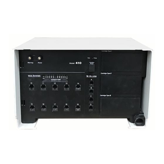
CONTROL UNIT The control unit provides power for most voice terminals and accessories. All outside lines and all voice terminals and telephones connect to the control unit, which contains the microprocessor and memory for all the advanced features available with the MERLIN communications system. - Page 10 Physical Features of the Model 206 and 410 Control Units (Model 410 is pictured) Voice Terminals jacks: Jacks labeled 0 through 5 (Model 206) or 10 through 19 (Model 410) accommodate MERLIN system voice terminals. Warning light (red): Comes on momentarily when the ac power cord is first plugged in. If the warning light remains on, it can also indicate trouble.
- Page 11 Model 820 Control Unit Behind the removable front panel of the Model 820 control unit is one line/voice terminal module that accommodates 2 outside lines and 5 voice terminals. The Model 820 control unit can accommodate up to four line/voice terminal modules for a maximum of 8 outside line jacks and 20 voice terminal jacks (for more information on available types of modules, see page 12).
- Page 12 Tel. Co. Lines jacks: Jacks labeled A and B on the 2-Line/5-Voice Terminal Module shipped with the control unit provide connections for outside lines. Voice Terminals jacks: Jacks labeled 10 through 14 on the 2-Line/5-Voice Terminal Module shipped with the control unit provide connections for MERLIN system voice terminals.
- Page 13 TYPE I CARTRIDGES: FEATURE PACKAGES A Type I cartridge occupies the top slot on the right side of the control unit. This cartridge contains all the programming for the custom features of the MERLIN system. (Without this cartridge, the system has standard features only.) The individual voice terminal has no memory or programming capabilities itself.
- Page 14 TYPE II CARTRIDGES: AUDIO OPTIONS A Type II cartridge provides connections for such features as Loudspeaker Paging, Background Music, and Music-on-Hold. It is installed in the second slot on the right side of the control unit. Pictured below is the Music-on-Hold/Paging Cartridge. A Music-on-Hold Type II cartridge with only the Music-on-Hold feature is also available;...
- Page 15 TYPE III CARTRIDGES: LINE-ASSOCIATED OPTIONS A Type III cartridge provides line-associated options. It is installed in the third or last slot on the right side of the control unit. Pictured below is the Extra Alert/2-Line Power Transfer Type III cartridge. Power Fail Lines jacks: Connect two basic Touch-Tone or rotary telephones for automatic backup...
- Page 16 OFF-PREMISES TELEPHONE INTERFACE TYPE C (Optional) The Off-Premises Telephone Interface is optional. This unit connects off-premises telephones to the MERLIN communications system, making the advanced features available to the off- premises user. The unit can be mounted on the wall or placed near the control unit. Power is supplied directly through the voice terminal module jack connection described below.
- Page 17 VOICE TERMINALS Several types of voice terminals may be connected to Models 206, 410, and 820. They are distinguished from one another by the number of silver membrane buttons above and to the right of the dial pad. These buttons give access to lines and features; most buttons are programmable.
- Page 18 OPTIONAL EQUIPMENT In addition to the essential components of the MERLIN communications system, several different accessories may be connected to voice terminals or the control unit. Optional Voice Terminal Accessories Hands-Free Units, Headset Adapters, and Manual Multipurpose Adapters can be connected directly to the underside of the voice terminal as illustrated below.
- Page 19 Headset Adapter The Headset Adapter makes it possible to use a headset with a 10-button or 34-button voice terminal. Headset light: Goes on when headset is in use. On/Quiet switch: Turns adapter sound on; when held down, provides “mute” function. Off switch: Turns adapter sound off.
- Page 20 Manual Multipurpose Adapter The Manual Multipurpose Adapter (illustrated below) permits these devices to be connected to a voice terminal: Modems and data terminals with built-in modems. (An extra telephone is not needed with an AT&T 212A-type modem with a special cable. Automatic answering modems cannot be used.) Basic Touch-Tone or rotary telephones.
- Page 21 Control Unit Accessories Some optional accessories connect directly to the control unit to give the MERLIN system additional capabilities. Extra Alerts Extra alerts such as horns and bells provide signaling in large, open areas (for example, warehouses and parking lots) and especially noisy environments. Extra alerts connect either directly to the Services Module on the control unit or by the Extra Alert Switch.
- Page 22 Auxiliary Power Unit (Model 820 only) The Auxiliary Power Unit connects to the Model 820 control unit to provide the extra power necessary in systems with many accessories or 34-button deluxe voice terminals. Follow these steps to see if the system requires an Auxiliary Power Unit. Count how many voice terminals are connected to the control unit.
-
Page 24: Isolating And Correcting Troubles
Isolating and Correcting Troubles To isolate and correct a trouble: FIRST: Determine if more than one voice terminal or basic Touch-Tone or rotary telephone is experiencing the trouble. SECOND: If the trouble appears on only one voice terminal or telephone, find the symptom in the list below titled “A. -
Page 25: Trouble On One Telephone
TROUBLE ON ONE TELEPHONE Ringing Symptoms A1-3 A line rings but no caller is on the line 10-button voice terminals exhibit peculiar ringing and/or extra lights are lit A1-3 Voice terminal rings constantly, whether on or off hook A1-4 Voice terminal does not ring when a call is transferred to it A1-5 Off-premises telephone rings after user hangs up A1-5... - Page 26 A1-2...
-
Page 27: Ringing
TROUBLE ON ONE TELEPHONE Ringing A line rings but no caller is on the line. (The user attempts to answer a call but Symptom: loses it and receives dial tone on a different line.) Recommended Action Possible Cause Rocking the handset causes the voice terminal to User rocked the handset while lifting go off hook, on hook, then off hook again. -
Page 28: Voice Terminal Rings Constantly, Whether On Or Off Hook
TROUBLE ON ONE TELEPHONE Ringing Symptom: Voice terminal rings constantly, whether on or off hook. Recommended Action Possible Cause 1. Make sure the T/P switch is in the center 1. Voice terminal T/P switch is not position. in center position. 2. -
Page 29: Voice Terminal Does Not Ring When A Call Is Transferred To It
TROUBLE ON ONE TELEPHONE Ringing Voice terminal does not ring when a call is transferred to it. (The Transfer feature Symptom: is available only if the system has a feature cartridge.) Recommended Action Possible Cause If the green light is on by a Do Not Disturb button, Do Not Disturb feature is activated. -
Page 30: Voice Terminal Does Not Ring On Incoming Outside Calls
TROUBLE ON ONE TELEPHONE Ringing Symptom: Voice terminal does not ring on incoming outside calls on one or more lines Possible Cause Recommended Action 1. Volume control setting is too Slide volume control to a higher position and low. test by making a call to one of the user’s outside lines from another voice terminal. - Page 31 TROUBLE ON ONE TELEPHONE Ringing 3. If the green light is on by a Do Not Disturb Do Not Disturb feature is button, touch the button to deactivate the activated (applies only if the feature. system has a feature cartridge). Do Not Disturb may be programmed on a button without lights beside it, a mislabeled button, or an unlabeled button.
- Page 32 TROUBLE ON ONE TELEPHONE Dialing Symptoms User hears dial tone but cannot dial out A2-3 User cannot program alternate long-distance or other computer-based services on Outside Auto Dial buttons A2-3 User lifts handset and does not hear dial tone A2-4 When trying to access Centrex, PBX, or custom calling features, dialing # and a 2-digit feature code does not work A2-5...
- Page 33 A2-2...
-
Page 34: Dialing
TROUBLE ON ONE TELEPHONE Dialing Symptom: User hears dial tone but cannot dial out. Recommended Action Possible Cause 1. If you have a feature cartridge, the voice 1. Voice terminal is restricted. terminal may be intentionally restricted from (This feature is available only on certain feature cartridges.) dialing outside numbers. - Page 35 TROUBLE ON ONE TELEPHONE Dialing User lifts handset and does not hear dial tone. Symptom: Recommended Action Possible Cause 1. If you have a feature cartridge, the voice 1. Voice terminal incompletely terminal may be intentionally restricted from outward call restricted (applies making outside calls.
- Page 36 TROUBLE ON ONE TELEPHONE Dialing When trying to access Centrex, PBX, or custom calling features, dialing # and a Symptom: 2-digit feature code does not work. (This feature is available only on feature cartridge with the Speed Dialing feature.) Possible Cause Recommended Action Dialing # and a 2-digit code is To access a Centrex, PBX, or custom calling...
- Page 37 TROUBLE ON ONE TELEPHONE Dialing Symptom: Off-premises telephone has no dial tone and cannot receive calls. Possible Cause Recommended Action Test the jack by plugging a MERLIN system Voice terminal jack in the voice terminal into the jack. control unit is faulty. Make sure wiring is not damaged and Wiring between the off- connectors are plugged in securely between...
- Page 38 TROUBLE ON ONE TELEPHONE Hearing Symptoms User in a noisy room has trouble hearing outside or intercom calls A3-3 User hears excessive breath noises from himself or herself A3-3 User with off-premises telephone has trouble hearing A3-4 Outside caller intermittently has trouble hearing a user A3-5 NOTE: Use this section only if you have isolated the problem to one voice terminal or telephone (in other words, it is not a systemwide problem).
- Page 39 A3-2...
-
Page 40: Hearing
TROUBLE ON ONE TELEPHONE Hearing Symptom: User in a noisy room has trouble hearing outside or intercom calls. Possible Cause Recommended Action 1. Instruct the user to hold the handset farther 1 . User is holding the handset too from his or her mouth. near his or her mouth. - Page 41 TROUBLE ON ONE TELEPHONE Hearing Symptom: User with off-premises telephone has trouble hearing. Possible Cause Recommended Action 1. Off-premises telephone may be 1. Switch the suspect off-premises telephone with a basic Touch-Tone or rotary telephone defective. known to be working properly. Place an outside call.
-
Page 42: Hearing A3
TROUBLE ON ONE TELEPHONE Hearing Symptom: Outside caller intermittently has trouble hearing a user. Possible Cause Recommended Action Radio-frequency interference (RFI) is Certain early production voice terminals may be occurring. susceptible to high RFI levels. Voice terminals manufactured beginning April 1983 have improved RFI immunity. - Page 43 TROUBLE ON ONE TELEPHONE Light Symptoms Voice terminal behaves abnormally in the test mode (T setting of T/P switch) A4-3 NOTE: Use this section only if you have isolated the problem to one voice terminal or telephone (in other words, it is not a systemwide problem). A4-1...
- Page 44 A4-2...
-
Page 45: Lights
TROUBLE ON ONE TELEPHONE Lights Voice terminal behaves abnormally in the test mode (T setting of T/P switch). Symptom: Normally, when a voice terminal is in the test mode, the red and green lights flash alternately and a tone sounds regularly. Recommended Action Possible Cause Make sure the wires from the cable are... - Page 46 TROUBLE ON ONE TELEPHONE Lights 4. Make sure all cords are labeled before 4. Control unit is defective. unplugging them from the control unit. Unplug the voice terminal extension cord or jumper cord from the control unit. Plug the cord into a different Voice Terminals jack on the control unit.
- Page 47 TROUBLE ON ONE TELEPHONE Feature Symptoms A5-3 Voice terminal speaker squeals when user hangs up handset User can dial out normally from dial pad but Outside Auto Dial button does not work A5-3 User attempts to retrieve a held call and loses it A5-4 A call cannot be conferenced A5-4...
- Page 48 A5-2...
-
Page 49: Features
TROUBLE ON ONE TELEPHONE Features Voice terminal speaker squeals when user hangs up handset (applies only if the Symptom: system has a feature cartridge). Possible Cause Recommended Action The speaker is on and sets up a Instruct the user to turn the speaker off before feedback path with the handset hanging up the handset. -
Page 50: User Attempts To Retrieve A Held Call And Loses It
TROUBLE ON ONE TELEPHONE Features Symptom: User attempts to retrieve a held call and loses it. Recommended Action Possible Cause Rocking the handset causes the voice terminal to User rocked the handset while lifting go off hook, on hook, and then off hook again. Instruct the user to lift the handset without rocking it to either side. -
Page 51: Toll Call Restricted Voice Terminal Is Unable To Make A Local Call
TROUBLE ON ONE TELEPHONE Features Symptom: Toll call restricted voice terminal is unable to make a local call. Recommended Action Possible Cause Set the switch to Toll Prefix if you must dial 0 1. Toll Prefix/Area Code switch on or 1 before you dial an area code. the control unit may be in wrong position. - Page 52 TROUBLE ON ONE TELEPHONE Features Symptom: Administrator cannot restrict outside calls at a voice terminal. Possible Cause Recommended Action 1. Set the switch to Toll Prefix if you must dial 0 1. Toll Prefix/Area Code switch or 1 before you dial an area code. may be in wrong position.
- Page 53 TROUBLE ON ONE TELEPHONE Features Intercom calls to a 5- or 10-button voice terminal get a busy signal but the user is Symptom: not on another line. Outside calls do not ring on the voice terminal either. Recommended Action Possible Cause The Do Not Disturb feature is If the green light is on by a Do Not Disturb button, touch the button to deactivate the feature.
-
Page 54: Voice Terminal More Than 200 Feet From A Model 206 Control Unit Does Not Operate Properly
TROUBLE ON ONE TELEPHONE Features Voice terminal more than 200 feet from a Model 206 control unit does not operate properly. Some of the specific symptoms are: Lights do not flash alternately in test mode. Symptom: Buttons click when pressed but do not respond. Intercom calls from other users receive a busy signal even when the voice terminal is idle. -
Page 55: User With An Off-Premises Telephone Cannot Put A Call On Hold
TROUBLE ON ONE TELEPHONE Features User with an off-premesis telephone drops the first outside call while attempting to Symptom: conference a second outside call. Recommended Action Possible Cause Instruct the user to follow this procedure when The user has put the first call on conferencing calls: hold before dialing the second call. - Page 56 TROUBLE ON ONE TELEPHONE Accessory Symptoms Lights behave abnormally on a 34-button voice terminal with Hands-Free Unit A6-3 NOTE: Use this section only if you have isolated the problem to one voice terminal or telephone (in other words, it is not a systemwide problem). A6-1...
- Page 57 A6-2...
-
Page 58: Accessories
TROUBLE ON ONE TELEPHONE Accessories Lights behave abnormally on a 34-button deluxe voice terminal with Hands-Free Symptom: Unit. This may occur at system installation or after a power failure. Recommended Action Possible Cause Add a Voice Terminal Power Supply, or, each time Too much start-up load is being the power fails or the control unit is reset, do the placed on the control unit. - Page 59 TROUBLE ON ONE TELEPHONE Miscellaneous Symptoms Outside lines added to the system do not appear at the attendant position A7-3 Outside lines taken away from the system still appear at the attendant position A7-3 A voice terminal or voice terminal accessory suddenly fails A7-4 NOTE: Use this section only if you have isolated the problem to one voice terminal or telephone (in other words, it is not a systemwide problem).
- Page 60 A7-2...
-
Page 61: Miscellaneous
TROUBLE ON ONE TELEPHONE Miscellaneous Outside lines added to the system do not appear at the attendant position (applies Symptom: only to systems with certain feature cartridges). Possible Cause Recommended Action Refer to the administration manual that came with The lines added to the system were the feature cartridge for instructions on not administered to the system. - Page 62 TROUBLE ON ONE TELEPHONE Miscellaneous Symptom: A voice terminal or voice terminal accessory suddenly fails. Possible Cause Recommended Action A surge of static electricity occurred. If new carpeting is causing the static electricity, spray the area with an antistatic spray. Make sure the control unit is connected to a third- wire (green-wire) ground.
-
Page 63: Trouble On Several Telephones
TROUBLE ON SEVERAL TELEPHONES Ringing Symptoms A particular outside line does not ring B1-3 Voice terminals have a peculiar ring, lights flash randomly, and users often hear clicks through the handset B1-5 B1-1... - Page 64 B1-2...
-
Page 65: Ringing
TROUBLE ON SEVERAL TELEPHONES Ringing Symptom: A particular outside line does not ring. Other lines do ring. Recommended Action Possible Cause 1. See if dial tone is present on the line that does Wiring between the network not ring. If not, make sure wiring between interface and control unit is network interface and control unit is not faulty. - Page 66 TROUBLE ON SEVERAL TELEPHONES Ringing 3. Control unit is defective. Make sure all cords are labeled before unplugging them from the control unit. At the control unit, unplug the line cord for the line with trouble. Plug the line cord for another outside line into that jack.
- Page 67 TROUBLE ON SEVERAL TELEPHONES Ringing Voice terminals have a peculiar ring, lights flash randomly, and users often hear Symptom: clicks through the handset. Possible Cause Recommended Action Feature cartridge was plugged in Unplug the ac power cord, remove and reinsert the with ac power on.
- Page 68 TROUBLE ON SEVERAL TELEPHONES Dialing Symptoms B2-3 Dial tone is not present on a particular line but is heard on other lines Dial tone is present on all lines, but users cannot dial out on all lines B2-4 B2-1...
- Page 69 B2-2...
-
Page 70: Dialing
TROUBLE ON SEVERAL TELEPHONES Dialing Symptom: Dial tone is not present on a particular line but is heard on other lines. Recommended Action Possible Cause 1. Verify local telephone company line operation 1. Local telephone company line by plugging in a basic telephone at the is faulty. - Page 71 TROUBLE ON SEVERAL TELEPHONES Dialing Symptom: Dial tone is present on all lines, but users cannot dial out on all lines. Possible Cause Recommended Action 1. The Tone/Pulse option for 1. Set the Tone/Pulse switch on the control unit outside lines may be to Tone for Touch-Tone dialing service or misadministered.
- Page 72 TROUBLE ON SEVERAL TELEPHONES Hearing Symptoms Users cannot hear outside party clearly B3-3 B3-1...
- Page 73 B3-2...
-
Page 74: Hearing
TROUBLE ON SEVERAL TELEPHONES Hearing Symptom: Users cannot hear outside party clearly. Recommended Action Possible Cause 1 . Verify voice quality on local telephone Local telephone company line company line by plugging in a basic Touch- is faulty. Tone or rotary telephone at the network interface or jack field line jack. - Page 75 TROUBLE ON SEVERAL TELEPHONES Light Symptoms Voice terminal lights are dim, especially when the voice terminal T/P switch is in the T position (Model 820 only) B4-3 Voice terminal red and green lights do not flash alternately in test mode B4-4 Control unit red Warning light flutters and feature catridge is in place Users cannot place or receive calls...
- Page 76 B4-2...
-
Page 77: Lights
TROUBLE ON SEVERAL TELEPHONES Lights Voice terminal lights are dim, especially when the voice terminal T/P switch is in Symptom: the T position (Model 820 only). Recommended Action Possible Cause To supply more power to 34-button deluxe voice The control unit is not supplying terminals, use Voice Terminal Power Supplies. - Page 78 TROUBLE ON SEVERAL TELEPHONES Lights Voice terminal red and green lights do not flash alternately in the test mode Symptom: (T setting of T/P switch). Possible Cause Recommended Action 1. The red Warning light on the 1. Reset the control unit by unplugging the ac control unit may be on.
- Page 79 TROUBLE ON SEVERAL TELEPHONES Feature Symptoms User cannot pick up a call transferred from another user B5-3 Last Number Redial and Saved Number Redial features do not work on a MERLIN system operating behind a PBX B5-3 B5-4 Outside Auto Dial feature does not work B5-1...
- Page 80 B5-2...
-
Page 81: Features
TROUBLE ON SEVERAL TELEPHONES Features User cannot pick up a call transferred from another user (applies only if the Symptom: system has a feature cartridge). Possible Cause Recommended Action 1. The Do Not Disturb feature may 1. Check Do Not Disturb feature: be activated on the voice terminal to which the call is If the green light is on by a Do Not Disturb... - Page 82 TROUBLE ON SEVERAL TELEPHONES Features Outside Auto Dial feature does not work (applies only if the system has a feature Symptom: cartridge). Recommended Action Possible Cause 1. Make sure the Tone/Pulse switch at the The tone/pulse option has been control unit is set to Tone for Touch-Tone misadministered.
- Page 83 TROUBLE ON SEVERAL TELEPHONES Accessory Symptoms Music-on-Hold, Background Music, and/or Loudspeaker Paging are too loud or too soft B6-3 B6-1...
- Page 84 B6-2...
-
Page 85: Accessories
TROUBLE ON SEVERAL TELEPHONES Accessories Music-on-Hold, Background Music, and/or Loudspeaker Paging are too loud or too Symptom: soft. Possible Cause Recommended Action One or more of the following may Follow the instructions for the numbered step that need adjustment: applies to your music and/or paging accessories. Music source level NOTE: To hear Music-on-Hold as you adjust the Paging amplifier level... - Page 86 TROUBLE ON SEVERAL TELEPHONES Accessories If you have Music-on-Hold but no Background Music: Turn the Background Music volume control on the cartridge fully counterclockwise (off). Turn the Music-on-Hold volume control fully counterclockwise, then clockwise until the music volume (as heard through a voice terminal) is acceptable.
- Page 87 TROUBLE ON SEVERAL TELEPHONES Entire System Down Symptoms Entire system is down. Red and green lights on control unit are not lit. B7-3 System is totally inoperative B7-4 Green Power light on the control unit is off, but there is no power failure B7-1...
- Page 88 B7-2...
-
Page 89: Entire System Down
TROUBLE ON SEVERAL TELEPHONES Entire System Down Entire system is down. Red and green lights on control unit are not lit. System is Symptom: totally inoperative. Possible Cause Recommended Action There is no ac power. 1. Make sure the control unit is not connected to an outlet controlled by a switch. - Page 90 TROUBLE ON SEVERAL TELEPHONES Entire System Down Symptom: Green Power light on the control unit is off, but there is no power failure. Recommended Action Possible Cause 1. Unplug the control unit ac power cord. 1. One or more cartridges are Remove and securely replace each cartridge.
- Page 91 TROUBLE ON SEVERAL TELEPHONES Miscellaneous Symptoms An outside call is dropped during conversation B8-3 MERLIN system interferes with television reception B8-4 B8-1...
- Page 92 B8-2...
-
Page 93: Miscellaneous
TROUBLE ON SEVERAL TELEPHONES Miscellaneous Symptom: An outside call is dropped during conversation. Possible Cause Recommended Action Another user may have joined the call and 1. A user made an error. touched Recall. Instruct the user to redial the call. 2. - Page 94 TROUBLE ON SEVERAL TELEPHONES Miscellaneous Symptom: MERLIN system interferes with television reception. Recommended Action Possible Cause Follow these steps to improve television reception: Control unit is too close to the television. Reorient the television antenna. Plug the control unit and the television receiver into different outlets so they are on different branch circuits.
- Page 95 Customer Instruction Booklets CIB 2852: (7302 H01) 5-Button Voice Terminal (3160) CIB 2853: (7303 H01) 10-Button Voice Terminal (3161) (10A) 5- and 10-Button Voice Terminal Fixed Desk Stand (32004) CIB 2854: (11A) 10-Button Voice Terminal Adjustable Desk Stand (32002) CIB 2855: (201A) 10-Button Voice Terminal Wall Mount (32001) CIB 2856: CIB 2858:...
- Page 96 CIB 2852 (7302 H01) 5-BUTTON VOICE TERMINAL (3160) The 5-Button Voice Terminal provides ac- Mount the voice terminal on the desk Press this ridge with your finger while cupping the rail in the palm of cess to intercom and outside lines, and to stand or wall mount.
- Page 97 CIB 2853 (7303 H01) 10-BUTTON VOICE TERMINAL (3161) Speaker/Ring Volume Control HANDSET The 10-Button Voice Terminal provides ac- REMOVE TO PLUG cess to intercom and outside lines, and to 'LINE' The volume control is located on the left side IN HANDS– JACK programmable and other button features FREE UNIT...
- Page 98 CIB 2854 (10A) 5- AND 10-BUTTON VOICE TERMINAL FIXED DESK STAND (32004) REMOVAL INSTRUCTIONS This stand is a fixed mounting base for the 7103, 7302, and 7303 Voice Terminals. Turn the voice terminal over. Depress the locking tab of INSTALLATION INSTRUCTIONS the 5-Button Voice Termi- nal (see Figure 2).
- Page 99 CIB 2855 (11A) 10-BUTTON VOICE TERMINAL ADJUSTABLE DESK STAND (32002) To LOWER — Using the This desk stand is an adjustable Gently slide the stand up- ward so that the voice ter- right hand, lift the rear mounting base for the 7103 and 7303 Voice Terminals and minal tabs fit firmly into of the voice terminal to...
- Page 100 CIB 2856 (201A) 10-BUTTON VOICE TERMINAL WALL MOUNT (32001) This bracket is used to mount 7103 or Position the two upper mounting slots NUMBER STRIP 7303 Voice Terminals on a wall surface. onto the screws and slightly tighten (see Figure 2E). Insert the two remaining screws into INSTALLATION INSTRUCTIONS (EXAMPLE)
- Page 101 REMOVE TO PLUG IN HANDS-FREE UNIT TO 'LINE' OR OTHER JACK ACCESSORY 'OTHER' JACK 'LINE' JACK CORD SLOT Figure 8 Position the back (or bottom) of the voice terminal so the three terminal mounting tabs (Figure 9) fit into the terminal mounting slots.
- Page 102 CIB 2858 (103A) CUSTOMER-INSTALLABLE JACK (32601) cutters, near the plastic The customer-installable jack is MOUNTING HOLES caps, ensuring that the used to connect 4-pair DIW ca- wire ends are not touch- ble to a D8-type modular cord. ing each other (Figure 4). INSTALLATION INSTRUCTIONS Remove the cover from the customer-installable...
- Page 103 CIB 2859 (742D) CONNECTING BLOCK (A special tool This connecting block Repeat Step 7 With a pair of pli- for this purpose joins 8-conductor, 22- for the other ca- ers, remove a is available, the 24 gauge, inside wire breakout from ble with the (DIW) cables quickly 953A Cable Strip-...
- Page 104 CIB 2860 (700A8) MODULAR PLUG did in Step 3. The se- Place the bottom piece on The modular plug permits an 8- quence of wire colors is a flat surface. Position the conductor, 22-24 gauge, inside coded by number: top piece on the bottom wire (DIW) cable to be plugged piece;...
- Page 105 CIB 2861 (451A) ADAPTER The adapter is used to connect a voice terminal cord (D8W) to another voice terminal cord (D8W) or to a voice terminal ex- tension cord (D8AF). D8-TYPE MODULAR CORD D8-TYPE (Greenish-Yellow) MODULAR CORD (Greenish-Yellow) 451A ADAPTER INSTALLATION INSTRUCTIONS 1.
- Page 106 CIB 2863 (267C) TWO-LINE ADAPTER (61400) The two-line adapter is used to connect two line (D4CH) cords to a single network interface (RJ14C) where two outside telephone lines enter the premises. If you do not know whether you have two outside telephone lines entering at a single network interface, you can ask your Local Telephone Exchange Service Company.
- Page 107 CIB 2864 ISSUE 2 Instructions For S102A Hands-Free Unit (3163) (S102A) HANDS-FREE UNIT (3163) Operation of the Hands-Free Unit (HFU) or speakerphone makes it possible to place and answer both outside and intercom calls without using the handset of the associated voice terminal. The HFU can only be used with 10- and 34-Button Voice Terminals.
- Page 108 CIB 2864 OPERATING INSTRUCTIONS Leave the handset on the voice terminal. Press the SPEAKERPHONE ON/OFF button. The speakerphone and microphone lights come on (see Figure 2) and you will hear dial tone. Dial the number if placing a call. Begin your conversation. Slide the Volume Control lever for a comfortable listening level (see Figure 2).
- Page 109 CIB 2865 (7305 H01) 34-BUTTON VOICE TERMINAL (3162) REMOVING AND REPLACING Turn the voice terminal right side up. The 34-Button Voice Terminal provides ac- LABELS cess to intercom and outside lines, and to programmable and other button features Plug the loose end of the handset cord Removal shown in Figure 1 which may be provided into the handset (see Figure 2).
- Page 110 CIB 2866 (335A) AUXILIARY POWER UNIT (3165) An auxiliary power unit must be added to INSTALLATION INSTRUCTIONS WALL MOUNTING INSTRUCTIONS your control unit if the total number of voice terminals and voice terminal The auxiliary power unit may be surface accessories (hands-free unit, and headset mounted on a shelf or desk next to the Mounting on a Wood Surface...
- Page 111 MOUNTING PLATE E WALL MOUNT MOUNTING STUDS KEYHOLES Figure 4 Connections Unplug the control unit power cord from the wall outlet. Plug the control unit power cord into the “AC Output” outlet on the auxiliary power unit. Insert one end of the auxiliary power cord into the jack labeled “Auxiliary Power”...
- Page 112 TEAR ALONG THIS LINE AUXILIARY POWER UNIT OUTLINE MOUNTING PLATE OUTLINE MOUNTING HOLES TEAR ALONG THIS LINE...
- Page 113 CIB 2867 (502A) HEADSET ADAPTER (3164) If your headset has a 2- OPERATING INSTRUCTIONS The headset adapter makes it prong plug, insert it into possible to use a headset with the headset jack on the To place a call: press the the 10- and 34-Button Voice front of the adapter (see headset adapter “ON”...
- Page 114 CIB 2870 (150A) MUSIC-ON-HOLD CARTRIDGE TYPE II (6101) Connecting Your Music Source This cartridge (Figure 1) is intended for use with Models 206, 410, and 820 of the com- Note: This section explains how to munications system. When properly con- connect your music source to nected to a user-provided 2-watt, 8-ohm music source, it provides music to outside...
- Page 115 Tighten the screws. Plug the control unit power cord into a 117-volt ac electrical outlet not con- trolled by a switch. Plug the music source into a 117-volt ac electrical outlet; turn it on and set the volume control. Within your system, call from one line to another and have someone answer the called line.
- Page 116 CIB 2871 (151A) MUSIC-ON-HOLD/PAGING CARTRIDGE TYPE II (6102) Control Terminals This cartridge (Figure 1) is intended for use with the communications system, and pro- vides three functions: The “1” and “2” terminals on the car- tridge can be used for signaling the paging When properly connected to a system when a page is in progress (for ex- user-provided 2-watt, 8-ohm mu-...
- Page 117 Note: The Federal Communications cartridge to determine how to from the 8-ohm output of the Commission requires that sig- install your paging system to music source to the “M1” and nals be limited in loudness. If best suit your needs. “M2”...
- Page 118 CIB 2872 (170A) EXTRA-ALERT/2-LlNE POWER FAILURE CARTRIDGE TYPE III (6103) This cartridge (Figure 1) is in- Slide the cartridge into the Plug the control unit power tended for use with the Models control unit cartridge slot cord into a 117-volt ac 206 and 410 communications marked Cartridge Type III electrical outlet not con-...
- Page 119 CIB 2885 (14A) 5-BUTTON VOICE TERMINAL FIXED DESK STAND AND WALL MOUNT (32000) Position the stand on the voice termi- Select proper toggler for wall thickness This bracket supports a 7302 Voice Termi- nal either on a desk or mounted on a wall. nal so that the stand’s mounting slots or wall type: fit just below the mounting tabs of the...
- Page 120 10. Convert the 5-Button Voice Terminal HANDSET HANDSET from a desk terminal to a wall- RETAINER RETAINER AFTER mounted terminal by following these IN WALL ROTATION MOUNT steps: POSITION Remove the number card retainer and the number card (see Figure Remove the screw under the num- ber card and lift out the handset HANDSET...
- Page 121 CIB 2886 (11C) 34-BUTTON VOICE TERMINAL ADJUSTABLE DESK STAND (32003) This desk stand is an adjustable To LOWER — Using the Gently slide the stand up- mounting base for the 7205, ward so that the voice ter- right hand, lift the rear 7305, and 7405 Voice Termi- minal tabs fit firmly into of the voice terminal to...
- Page 122 CIB 2887 (203A) 34-BUTTON VOICE TERMINAL WALL MOUNT (32006) This bracket is used to mount 7205, 7305, Position the two upper mounting slots SWITCHHOOK and 7405 Voice Terminals on a wall sur- onto the screws and slightly tighten BUTTON face. (see Figure 2E).
- Page 123 Gently slide the voice terminal down- Thread one end of the D8W Modular ward so the three tabs fit into the Cord up through the cord slot in the smaller part of the corresponding wall mount, and plug the cord into the mounting slots (see Figure 10).
- Page 124 CIB 2888 (267A2) LINE BRIDGING ADAPTER (61401) This adapter kit contains a 267A2 Adapter. The adapter connects to a single modular jack network interface to provide two-jack access to the same line. This allows auxiliary devices such as telephone answering machines to be connected to the line. INSTALLATION INSTRUCTIONS The adapter may be used in any of the following configurations: NETWORK INTERFACE...
- Page 125 CIB 2893 (452A-50) EXTRA-ALERT CONTROL SWITCH (32630) This switch provides ON/OFF control, and is required for the proper installation of certain older extra-alert devices. TO EXTRA-ALERT BELL OR HORN CONTROL UNIT D4CH MODULAR LINE CORDS 453A-50 CONTROL SWITCH (ENLARGED 170A EXAMPLE) CARTRIDGE (TYPE III)
- Page 126 CIB 2903 (349A) ACOUSTIC COUPLER ADAPTER This adapter provides a means of mechanically connecting the voice terminal handset to the handset interface of existing acoustic modems. RECEIVER VOICE TERMINAL HANDSET INSTALLATION INSTRUCTIONS TRANSMITTER END Align the 349A Adapter’s SMALL transmitter (large retainer) RETAINER and receiver (small retainer) ends in the appropriate cups...
- Page 127 CIB 2923 (346A) ACOUSTIC COUPLER ADAPTER (31710) This adapter provides a means of mechanically connecting the voice terminal handset to the handset interface of existing acoustic modems. VOICE TERMINAL RECEIVER HANDSET TRANSMITTER END INSTALLATION INSTRUCTIONS SMALL RETAINER Align the 346A Adapter’s transmitter (large retainer) and receiver (small retainer) ends in the appropriate cups...
- Page 128 CIB 2924 (D181233) LINE-POWERED ALERT RINGER AND PARTS (61211) Test and Adjust Ringing The D181233 Line-Powered Alert Ringer and Parts Secure the 1049A Mounting Plate to the (see Figure 1) consists of an E1CM Ringer with a mounting surface using the appropriate fasteners 290A Adapter, a 1049A Mounting Plate, and a 25- (screws or togglers).
- Page 129 Method B. At the network interface jack with two-line appearances, plug a Two- Line Adapter (267C) into the line jack. Plug the Line Bridging adapter (267A2) into the line jack of the two-line adapter that is to have remote ringing. Insert the plug end of a Line Extension Cord (D4CE-50) into one jack on the line bridging adapter.
- Page 130 CIB 3000 (7305 H02) 34-BUTTON DELUXE VOICE TERMINAL (3166) The 34-Button Deluxe Voice Terminal (Fig- REMOVING AND REPLACING Turn the voice terminal right side up. ure 1) provides access to intercom and LABELS outside lines, and to programmable and Plug the loose end of the handset cord other button features which may be pro- Removal into the handset (see Figure 2).
- Page 131 CIB 3002 (Z200A) 2–LINE/5–VOICE TERMINAL MODULE FOR MODEL 820 (61219) CONTROL UNIT This module (Figure 1) is used to expand the capacity of your Model 820 control unit. Addition of this module wiII enable you to have two more outside lines and five voice terminals.
- Page 132 TEMPLATE WALL MOUNTING KIT INSTALLATION INSTRUCTIONS Choose a location for your control unit according to the instructions in your installation manual. Hold the template up to the location; make sure it is level; then mark where the two mounting holes should go. (pierce the center of the holes with a small nail or equivalent).
- Page 133 SYSTEM DIRECTORY — MODEL 820 System Directory — adhesive-backed label to be filled out with essential system and user information and attached to the control unit door. Wall Mounting Your Control Unit Choose a location for your control unit according to the instructions in your “Installa- tion Manual.”...
- Page 134 PRINTED IN U.S.A. CIB 3004 Instructions For (Z110A) MODEL 820 CONTROL UNIT INSTALLATION KIT (6120) CIB 3004 Issue 1 Copyright © 1984 AT&T Technologies All rights reserved Equipment manufactured by AT&T Technologies in the U.S.A.
- Page 135 This kit contains items needed to install your Model 820 control unit. Instructions for us- ing the wall mounting kit are included here; instructions for using other items are included in your Installation Manual. You may not use all these items during your initial installation. SAVE unused items in the storage box for later changes or growth in your system.
- Page 136 (Z110A) MODEL 820 CONTROL UNIT INSTALLATlON KIT (6120) Two-Line Adapter — used to connect two line cords to a single network interface (RJ14C) where two outside telephone lines enter the premises Cord Clips (Pack of 10) — adhesive-backed clips to fasten cords to the wall Line Cords (Two) —...
- Page 137 CIB 3004 LINE CORD LABELS I.J.002 A A B B C C D D E E F F G G H H A A B B C C D D E E F F G G H H A A B B C C D D E E F F G G H H A A B B C C D D E E F F G G H H A A B B C C D D E E F F G G H H A A B B C C D D E E F F G G H H...
- Page 138 CIB 3006 © 1984 AT&T All Rights Reserved...
- Page 139 WIRING INSTALLATION INSTRUCTIONS These instructions explain how to install building wiring for telephones. The instructions are intended for someone familiar with building construction. When you finish these procedures, you will have: Control unit location a jack field installed near your control unit location jumper cords plugged into the...
- Page 140 Installing your wiring involves these four steps: Getting started Mounting the jack panels Running cable and installing modular jacks Connecting jumper cords. WARNING: National and local building codes and fire regulations forbid routing flammable wiring inside or on top of air plenums or ducts or along hot pipes.
- Page 141 GETTING STARTED You will need these materials: a floor plan of your building that shows telephone locations and cable routes between these locations and your communications system control unit a screwdriver scissors drill and bits appropriate for 3/16-inch cable. Small cable clips are provided, but you may also want bigger clips, cable ties, and a stapler and staples for fastening cables.
- Page 142 CABLE EXTENSION KIT (one per telephone more than 10 feet from the control unit) Modular jack 100- or 200-foot length of cable (Length depends on distance between control unit and telephone.) Cable clips WIRING TERMINATION KIT (one per telephone) Cable clips Jumper cord Modjack-to-modjack adapter Look for the telephone locations on your building floor plan.
- Page 143 MOUNTING THE JACK PANEL BOXES On your building floor plan, pencil in the control unit location. The location must comply with the measurements shown in the figure. Control unit location 2 inches from control Minimum of 2 feet off floor unit or bottom of shelf (if control unit will rest on shelf)
- Page 144 On the wall, mark where the bottom of the control unit or shelf (if the control unit will rest on a shelf) will be. Screws 1-1/4 inches long come with the jack panel boxes. Choose one of the following methods for mounting the boxes (don’t mount the boxes yet): For walls with a sturdy supporting structure (studs or cross members): Attach boxes directly with the screws...
- Page 145 Mount the jack panel box with the screws provided or fasteners appropriate for your walls. Mesh the tongue and groove of another jack panel box with the first. Mount the second box.
- Page 146 Tongue and groove Mount the remaining jack panel boxes in the same way. Black dot Snap six modjack-to-modjack adapters into each jack retainer. Position the black dot on the left.
- Page 147 RUNNING CABLE AND INSTALLING MODULAR JACKS When completed, a typical cable run will look like this. Special types of cable such as flat under-carpet cable, plenum wiring, flameproof wiring, and 25-pair cable may be available from your dealer. Cable clip Identical labels Cable TELEPHONE...
- Page 148 Select a Cable Extension Kit with the right length of cable (100 or 200 feet) for one cable run. For runs over 200 feet, you will have to run a 200 foot cable, terminate it in a modular jack, and plug in another cable. The maximum length of any cable run is 1000 feet.
- Page 149 Find the modular jack from the Cable Extension Kit and the cable installation tool from the Wiring Installation Kit. Choose the location for the jack according to the figure. Cut the cable, making sure you allow at least 4 inches extra.
- Page 150 Insert wires in this order left to right: 1 white-blue 2 b l u e Remove and save 3 white-orange plastic caps 4 orange 5 white-green 6 green 7 white-borwn 8 b r o w n Align caps and press them down firmly until they snap in place.
- Page 151 Route your other cables and terminate each one in a modular jack. Be sure to label both ends of each cable run identically. Dress the cables and, if you used cable ties, secure them around the cables. Dress the cables neatly through the lower openings and secure them with cable clips or ties.
- Page 152 CONNECTING JUMPER CORDS Plug a jumper cord (from a Wiring Termination Kit) into each left modjack. Drape the cords as shown. They will later be connected Close the right doors of the to the control unit. jack panel boxes. Close the left doors of the jack panel boxes.
- Page 153 CIB 3007 ADJUNCT POWER SUPPLY FOR 34-BUTTON DELUXE VOICE TERMINAL (D181282) (32811) The Adjunct Power Supply (Figure 1) for the 34-Button Deluxe Plug the Z400F Adapter into the modular terminal jack or Voice Terminal comes packed with a Z400F Adapter and a extension cord from which the modular terminal cord was 7-foot cord (D6AP).
- Page 154 CIB 3011 (Z111A) FEATURE PACKAGE 2 CARTRIDGE TYPE I (6104) This Feature Package 2 Cartridge (Figure 1) can be installed in your Communications System Control Unit Models 206, 410, and 820. When installed, custom features can be programmed into your system to expand system capabilities. A.
- Page 155 Peel off backing and place label around switches as shown in Figure 3 or 4 as applicable. Press firmly to ensure adherence. Important: If you have just installed Feature Package 2 for the first time, you should do a system reset to clear memory before programming any of the features.
- Page 156 CIB 3012 (Z201A) 5-VOICE TERMINAL EXPANSION MODULE FOR MODEL 820 (61218) MODULE The 5-Voice Terminal Expansion Module (Figure 1), when in- SLOTS stalled in a Model 820 control unit, permits connection of five additional voice terminals to the system. Z6C DOOR Figure 2 LOCKING TAB Figure 1...
- Page 157 CIB 3029 Z110B MODEL 206 CONTROL UNIT INSTALLATION KIT (PEC 6106) This kit contains items needed to install your Model 206 control unit. Instructions for using the wall mounting kit are included here; instructions for using other items are included in your Installation Guide: Models 206 and 410.
-
Page 158: Voice Terminals
TERMINAL CORD LABELS Jack Field Terminal Side Wiring Run Labels Please Use Pencil On Labels Please Don't Discard Please Don't Discard Wiring run label pairs for identifying Terminal cord label pairs for identifying each end of the wiring run between the intercom numbers at the control unit and control unit or jack field and the voice voice terminals... - Page 159 SIDE A USING THE WALL MOUNTING KIT WITH THE PLASTIC MOUNTING BRACKET The instructions below pertain to you if your kit contains a plastic mounting NOTE: bracket. If your wall mounting kit contains three aluminum brackets, please refer to the instructions on Side B. Choose the location for your control unit according to the instructions in your Installation Guide: Models 206 and 410.
- Page 160 USING THE WALL MOUNTING KIT WITH THE ALUMINUM BRACKETS SIDE B NOTE: The instructions below pertain to you if your kit contains three aluminum brackets. If your wall mounting kit contains a black plastic backplate, please refer to the instructions on Side A. Choose the location for your control unit according to the instructions in your Installation Guide: Models 206 and 410.
- Page 161 TEMPLATE FOR USE WITH THE PLASTIC MOUNTING BRACKET CONTROL UNIT OUTLINE MOUNTING PLATE OUTLINE...
- Page 162 TEMPLATE FOR USE WITH ALUMINUM BRACKETS...
- Page 163 CIB 3030 Z110C MODEL 410 CONTROL UNIT INSTALLATION KIT (PEC 6110) This kit contains items needed to install your Model 410 control unit. Instructions for using the wall mounting kit are included here; instructions for using other items are included in your Installation Guide: Models 206 and 410.
- Page 164 Wiring run label pairs for identifying each end of the wiring run between the Jack Field Terminal Side control unit or jack field and the voice Wiring Run Labels terminal location Please Use Pencil On Labels Pleae Don't Discard TERMINAL CORD LABELS Terminal cord label pairs for identifying intercom numbers at the control unit and voice terminals SYSTEM DIRECTORY —...
- Page 165 SIDE A USING THE WALL MOUNTING KIT WITH THE PLASTIC MOUNTING BRACKET The instructions below pertain to you if your kit contains a plastic mounting NOTE: bracket. If your wall mounting kit contains three aluminum brackets, please refer to the instructions on Side B. Choose the location for your control unit according to the instructions in your Installation Guide: Models 206 and 410.
- Page 166 USING THE WALL MOUNTING KIT WITH THE ALUMINUM BRACKETS SIDE B NOTE: The instructions below pertain to you if your kit contains three aluminum brackets. If your wall mounting kit contains a black plastic backplate, please refer to the instructions on Side A. Choose the location for your control unit according to the instructions in your Installation Guide: Models 206 and 410.
- Page 167 TEMPLATE FOR USE WITH ALUMINUM BRACKETS...
- Page 168 TEMPLATE FOR USE WITH THE PLASTIC MOUNTING BRACKET CONTROL UNIT OUTLINE MOUNTING PLATE OUTLINE...
- Page 169 CIB 3038 Z609A 4-WAY MODJACK ADAPTER Installation Instructions Description In the jackfield, find a jack panel box with a The 4-Way Modjack Adapter consists of one 4-pair yellow dot (for auxiliary equipment modjack and four 1-pair modjacks attached to a adapters).
- Page 170 Snap in the adapter so the black dot is on the side with the door handle. black dot handle 4. Connect wiring to the adapter according to the instructions in CIB 3006: Wiring Installation Instructions. Instructions For Z609A 4-Way Modjack Adapter CIB 3038 ISSUE 1...
-
Page 171: Index
Index NOTE: Pages within the individual trouble sections are numbered in an unusual way to make this manual easy to update. In page number A1-4, for instance, the A indicates the section—“A. Trouble on One Telephone.” The 1 indicates the first trouble category within that section—Ringing. - Page 172 2860: (700A8) Modular Plug (451A) Modular Extension Adapter 2861: 2863: (267C) 2-Line Adapter (61400) 2864: (S102A) Hands-Free Unit (3163) 2865: (7305 H01) 34-Button Voice Terminal (3162) 2866: (335A) Auxiliary Power Unit (3165) 2867: (502A) Headset Adapter (3164) 2870: (150A) Music-on-Hold Cartridge Type II (6101) 2871: (151A) Music-on-Hold/Paging Cartridge...
-
Page 173: User Hears Dial Tone But Cannot Dial Out
Control unit accessories Extra Alerts, 18 Auxiliary Power Unit, 19, CIB 2866 Control units Model 206, 6 — 7 Model 410, 6 — 7 Model 820, 8 — 9 Dialing symptoms (trouble on one telephone) off-premises telephone has no dial tone and cannot receive calls, A2-6 user cannot program alternate long-distance or other computer-based services on Outside... -
Page 174: User In A Noisy Room Has Trouble Hearing Outside Or Intercom Calls
Feature symptoms (trouble on one telephone) administrator cannot restrict outside calls at a voice terminal or basic telephone, A5-6 call cannot be conference, A5-4 intercom calls to a 5- or 10-button voice terminal get a busy signal but the user is not on another line, A5-7 user can dial out normally from dial pad but Outside Auto Dial button does not work, A5-3... - Page 175 Light symptoms (trouble on one telephone) voice terminal behaves abnormally in the test mode, A4-3 Light symptoms (trouble on several telephones) control unit red Warning light flutters and feature cartridge is in place, B4-4 voice terminal lights are dim, especially when the voice terminal is in test mode, B4-3 voice terminal red and green lights do not flash alternately in test mode, B4-4...
-
Page 176: Off-Premises Telephone Has No Dial Tone And Cannot Receive Calls
Off-premises telephone Off-Premises Telephone Interface, 13, CIB 3009 Off-premises telephone has no dial tone and cannot receive calls, A2-6 Off-premises telephone rings after user hangs up, A1-5 user with off-premises telephone cannot put a call on hold, A5-9 user with off-premises telephone has trouble hearing, A3-4 user with off-premises telephone hears intercom dial tone but cannot place an outside call, A2-5... - Page 177 Symptoms of trouble (on several telephones) accessory symptoms, B6 dialing symptoms, B2 entire system down symptoms, B7 feature symptoms, B5 hearing symptoms, B3 light symptoms, B4 miscellaneous symptoms, B8 ringing symptoms, B1 Telephones backup telephones, 12 cordless telephones, 17 Power Failure Transfer Telephones, 12 voice terminal.
Need help?
Do you have a question about the MERLIN 820 and is the answer not in the manual?
Questions and answers