Table of Contents
Advertisement
Copyright
This publication, including all photographs, illustrations and software, is protected
under international copyright laws, with all rights reserved. Neither this manual, nor
any of the material contained herein, may be reproduced without written consent of
the author.
Version 1.0A
Disclaimer
The information in this document is subject to change without notice. The manufac-
turer makes no representations or warranties with respect to the contents hereof and
specifically disclaims any implied warranties of merchantability or fitness for any
particular purpose. The manufacturer reserves the right to revise this publication and
to make changes from time to time in the content hereof without obligation of the
manufacturer to notify any person of such revision or changes.
Trademark Recognition
Microsoft, MS-DOS and Windows are registered trademarks of Microsoft Corp.
MMX, Pentium, Pentium-II, Pentium-III, Celeron are registered trademarks of Intel
Corporation.
Other product names used in this manual are the properties of their respective
owners and are acknowledged.
Federal Communications Commission (FCC)
This equipment has been tested and found to comply with the limits for a Class B
digital device, pursuant to Part 15 of the FCC Rules. These limits are designed to
provide reasonable protection against harmful interference in a residential installa-
tion. This equipment generates, uses, and can radiate radio frequency energy and, if
not installed and used in accordance with the instructions, may cause harmful inter-
ference to radio communications. However, there is no guarantee that interference
will not occur in a particular installation. If this equipment does cause harmful
interference to radio or television reception, which can be determined by turning the
equipment off and on, the user is encouraged to try to correct the interference by one
or more of the following measures:
•
Reorient or relocate the receiving antenna
•
Increase the separation between the equipment and the receiver
•
Connect the equipment onto an outlet on a circuit different from that to
which the receiver is connected
•
Consult the dealer or an experienced radio/TV technician for help
Shielded interconnect cables and a shielded AC power cable must be employed with
this equipment to ensure compliance with the pertinent RF emission limits govern-
ing this device. Changes or modifications not expressly approved by the system's
manufacturer could void the user's authority to operate the equipment.
Preface
Preface
Advertisement
Table of Contents

Subscribe to Our Youtube Channel
Related Manuals for ECS G41T-M2


Summary of Contents for ECS G41T-M2
- Page 1 Preface Copyright This publication, including all photographs, illustrations and software, is protected under international copyright laws, with all rights reserved. Neither this manual, nor any of the material contained herein, may be reproduced without written consent of the author. Version 1.0A Disclaimer The information in this document is subject to change without notice.
-
Page 2: Declaration Of Conformity
Declaration of Conformity This device complies with part 15 of the FCC rules. Operation is subject to the following conditions: • This device may not cause harmful interference, and • This device must accept any interference received, including interfer- ence that may cause undesired operation Canadian Department of Communications This class B digital apparatus meets all requirements of the Canadian Interference- causing Equipment Regulations. -
Page 3: Table Of Contents
T T T T T ABLE OF CONTENTS ABLE OF CONTENTS ABLE OF CONTENTS ABLE OF CONTENTS ABLE OF CONTENTS Preface Chapter 1 Introducing the Motherboard Introduction..................1 Feature....................2 Motherboard Components.............5 Chapter 2 7 7 7 7 7 Installing the Motherboard Safety Precautions................7 Choosing a Computer Case.............7 Installing the Motherboard in a Case..........7... - Page 4 PCI/PnP Setup..............37 PC Health Status..............37 Frequency/Voltage Control..........40 Load Default Settings............41 Supervisor Password............41 User Password..............42 Save & Exit Setup...............42 Exit Without Saving............42 Updating the BIOS..............43 45 45 45 45 Chapter 4 Using the Motherboard Software About the Software CD-ROM............45 Auto-installing under Windows Vista.........45 Running Setup..............46 Manual Installation................50 Utility Software Reference............50...
-
Page 5: Introducing The Motherboard
Chapter 1 Introducing the Motherboard Introduction Thank you for choosing the G41T-M2 motherboard. This motherboard is a high performance, enhanced function motherboard designed to support the LGA775 socket ® ® ® Intel Core 2 Quad/Core 2 Duo/Pentium Dual-Core/Celeron processors for high-end business or personal desktop markets. -
Page 6: Feature
Feature Processor ® The motherboard uses an LGA775 type of Intel Core 2 Quad/Core 2 Duo/ ® ® Pentium Dual-Core/Celeron processors that carries the following features: • Intel ® Core 2 Quad/Core 2 Duo/Pentium ® Dual-Core/Celeron ® pro- cessors • Supports a system bus (FSB) of 1333/1066/800 MHz •... -
Page 7: Onboard Lan
Onboard LAN • Supports PCI Express™ 1.1 • Integrated 10/100/1000 transceiver • Wake-On-LAN (WOL) and remote wake-up support Audio (optional) This motherboard may support either of the following Audio chipsets: • 5.1 Channel High Definition Audio Codec • ADCs support 44.1k/48k/96kHz sample rate •... -
Page 8: Bios Firmware
BIOS Firmware This motherboard uses AMI BIOS that enables users to configure many system features including the following: • Power management • Wake-up alarms • CPU parameters • CPU and memory timing The firmware can also be used to set parameters for different processor clock speeds. -
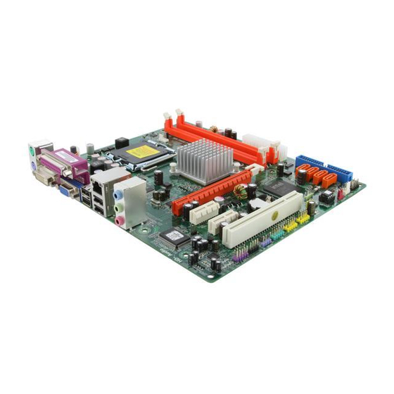
Page 9: Motherboard Components
Motherboard Components Table of Motherboard Components LABEL COMPONENTS ® LGA775 socket for Intel Core 2 Quad/Core 1. CPU Socket ® ® 2 Duo/Pentium Dual-core/Celeron processors 2. CPU_FAN CPU cooling fan connector 3. DDR2_1~2 240-pin DDR2 SDRAM slots 4. ATX_POWER Standard 24-pin ATX power connector 5. - Page 10 Memo Introducing the Motherboard...
-
Page 11: Installing The Motherboard
Chapter 2 Installing the Motherboard Safety Precautions • Follow these safety precautions when installing the motherboard • Wear a grounding strap attached to a grounded device to avoid dam- age from static electricity • Discharge static electricity by touching the metal case of a safely grounded object before working on the motherboard •... -
Page 12: Checking Jumper Settings
Do not over-tighten the screws as this can stress the motherboard. Checking Jumper Settings This section explains how to set jumpers for correct configuration of the motherboard. Setting Jumpers Use the motherboard jumpers to set system configuration options. Jumpers with more than one pin are numbered. -
Page 13: Checking Jumper Settings
Checking Jumper Settings The following illustration shows the location of the motherboard jumpers. Pin 1 is labeled. Jumper Settings Jumper Type Description Setting (default) 1-2: NORMAL 2-3: CLEAR CLR_CMOS 3-pin Clear CMOS Before clearing the CMOS, make sure to CLR_CMOS turn off the system. -
Page 14: Installing Hardware
Installing Hardware Installing the Processor Caution: When installing a CPU heatsink and cooling fan make sure that you DO NOT scratch the motherboard or any of the surface- mount resistors with the clip of the cooling fan. If the clip of the cooling fan scrapes across the motherboard, you may cause serious damage to the motherboard or its components. -
Page 15: Cpu Installation Procedure
CPU Installation Procedure The following illustration shows CPU installation components. A. Read and follow the instructions shown on the sticker on the CPU cap. B. Unload the cap · Use thumb & forefinger to hold the lifting tab of the cap. ·... -
Page 16: Installing Memory Modules
Installing Memory Modules This motherboard accommodates two memory modules. It can support two 240-pin DDR2 800/667. The total memory capacity is 8 GB. DDR2 SDRAM memory module table Memory module Memory Bus DDR2 667 333 MHz DDR2 800 400 MHz You must install at least one module in any of the two slots. - Page 17 Table A: DDR2 (memory module) QVL (Qualified Vendor List) The following DDR2 800/667 memory modules have been tested and qualified for use with this motherboard. Type Size Vendor Module Nam e Apacer 78.91G92.9K5 Micron MT4HTF6464AY-667E1 512 MB AL6E8E63J-6E1 Ramxel RML1520M38D6F-667 Samsung PC2-5300U-555-12-D3 AU01GE667C5KBGC...
- Page 18 Type Size Vendor Module Nam e KVR800D2N5/512 1.8V 9905315- Kingston 019.A02LF 512 MB Micron MT8HTF6464AY-80ED4 Qimonda HYS72T64000HU-2.5-B A-DATA M2GVD6G3I41P0U1E5E AET760UD00-30DB97X Aeneon AET760UD00-25DC08X AU01GE800C5KBGC Apacer 78.01GAO.9K5 78.01GA0.9L5 Geil Geil Millenary Hexon ELPT7AUDR-25M48 DDR2 800 Hynix HYMP112U64CP8-S6 AB KingMax KLDD48F-B8KU5 NGES 1 GB KVR800D2N5/1G 1.8V 9905316- Kingston 054.A01LF...
- Page 19 Type Size Vendor Module Nam e A-DATA Red A-data M2OMI6H3J4720L1C5Z Aeneon AET860UD00-25DC08X 78.A1GAO.9K4 Apacer 78.A1GC0.9L4 CORSAIR CM2X2048-6400C5 Geil Geil Platinum Edition Hexon ELPT8AUDR-25M88 Hynix HYMP125U64CP8-S6 AB KingMax KLDE88F-B8KU5 NHES 2 GB KVR800D2N5/2G Kingston DDR2 800 KVR800D2N6/2G-SP Micron MT16HTF25664AY-800E1 Nanya NT2GT64U8HD0BY-AD AL8E8F73C-8E1 Qimonda HYS64T256020EU-25F-C2...
-
Page 20: Expansion Slots
Expansion Slots Installing Add-on Cards The slots on this motherboard are designed to hold expansion cards and connect them to the system bus. Expansion slots are a means of adding or enhancing the motherboard’s features and capabilities. With these efficient facilities, you can in- crease the motherboard’s capabilities by adding hardware that performs tasks that are not part of the basic system. - Page 21 Follow these instructions to install an add-on card: Remove a blanking plate from the system case corresponding to the slot you are going to use. Install the edge connector of the add-on card into the expansion slot. Ensure that the edge connector is correctly seated in the slot. Secure the metal bracket of the card to the system case with a screw.
-
Page 22: Connecting Optional Devices
Connecting Optional Devices Refer to the following for information on connecting the motherboard’s optional devices: SATA1~4: Serial ATA connectors These connectors are used to support the new Serial ATA devices for the highest data transfer rates (3.0 Gb/s), simpler disk drive cabling and easier PC assembly. It elimi- nates limitations of the current Parallel ATA interface. - Page 23 F_USB1~2: Front Panel USB headers The motherboard has four USB ports installed on the rear edge I/O port array. Additionally, some computer cases have USB ports at the front of the case. If you have this kind of case, use auxiliary USB connector to connect the front-mounted ports to the motherboard.
-
Page 24: Installing A Hard Disk Drive/Cd-Rom/Sata Hard Drive
COM: Onboard serial port header Connect a serial port extension bracket to this header to add a second serial port to your system. Signal Name Function DCDB Data Carrier Detect SINB Serial Input SOUTB UART B Serial Output DTRB UART B Data Terminal Ready Ground DSRB Data Set Ready... - Page 25 About SATA Connectors Your motherboard features four SATA connectors supporting a total of four drives. SATA refers to Serial ATA (Advanced Technology Attachment) is the standard inter- face for the IDE hard drives which are currently used in most PCs. These connectors are well designed and will only fit in one orientation.
-
Page 26: Connecting I/O Devices
Connecting I/O Devices The backplane of the motherboard has the following I/O ports: PS2 Mouse Use the upper PS/2 port to connect a PS/2 pointing device. PS2 Keyboard Use the lower PS/2 port to connect a PS/2 keyboard. DVI Port Use the DVI port to connect the monitor. -
Page 27: Connecting Case Components
Connecting Case Components After you have installed the motherboard into a case, you can begin connecting the motherboard components. Refer to the following: Connect the CPU cooling fan cable to CPU_FAN. Connect the standard power supply connector to ATX_POWER. Connect the case switches and indicator LEDs to the F_PANEL. Connect the system cooling fan connector to SYS_FAN. - Page 28 CPU_FAN: CPU Cooling FAN Power Connector Signal Name Function System Ground +12V Power +12V Sense Sensor Users please note that the fan connector supports the CPU cooling fan of 1.1A ~ 2.2A (26.4W max) at +12V. ATX_POWER: ATX 24-pin Power Connector Signal Name Signal Name +3.3V...
- Page 29 ATX12V: ATX 12V Power Connector Signal Name Ground Ground +12V +12V Installing the Motherboard...
-
Page 30: Front Panel Header
Front Panel Header The front panel header (F_PANEL) provides a standard set of switch and LED headers commonly found on ATX or micro-ATX cases. Refer to the table below for information: Signal Function Signal Function HD_LED_P Hard disk LED (+) FP PWR/SLP *MSG LED (+) HD_LED_N Hard disk LED (-) FP PWR/SLP *MSG LED (-) -
Page 31: Using Bios
Chapter 3 Using BIOS About the Setup Utility The computer uses the latest “American Megatrends Inc. ” BIOS with support for Windows Plug and Play. The CMOS chip on the motherboard contains the ROM setup instructions for configuring the motherboard BIOS. The BIOS (Basic Input and Output System) Setup Utility displays the system’s configuration status and provides you with options to set system parameters. -
Page 32: Using Bios
Press the delete key to access the BIOS Setup Utility. CMOS Setup Utility - Copyright (C) 1985-2005, American Megatrends, Inc. Standard CMOS Setup Frequency/Voltage Control Advanced Setup Load Default Settings Advanced Chipset Setup Supervisor Password Integrated Peripherals User Password Power Management Setup Save &... -
Page 33: Standard Cmos Setup
For the purpose of better product maintenance, we reserve the right to change the BIOS items presented in the manual. The BIOS setup screens shown in this chapter are for reference only. Please visit our website for updated manual. Standard CMOS Setup This option displays basic information about your system. - Page 34 Primary IDE Master/Slave; SATA1~4 Your computer has one IDE channel and each channel can be installed with one or two devices (Master and Slave). In addition, this motherboard supports four SATA chan- nels and each channel allows one SATA device to be installed. Use these items to configure each device on the SATA channel.
-
Page 35: Advanced Setup
Advanced Setup This page sets up more advanced information about your system. Handle this page with caution. Any changes can affect the operation of your computer. CMOS Setup Utility - Copyright (C) 1985-2005, American Megatrends, Inc. Advanced Setup Help Item Thermal Management Enabled TM Status... - Page 36 Boot Up Numlock Status (On) This item defines if the keyboard Num Lock key is active when your system is started. APIC Mode (Enabled) This item allows you to enable or disable the APIC (Advanced Programmable Inter- rupt Controller) mode. APIC provides symmetric multi-processing (SMP) for sys- tems, allowing support for up to 60 processors.
-
Page 37: Advanced Chipset Setup
Advanced Chipset Setup This page sets up more advanced information about your system. Handle this page with caution. Any changes can affect the operation of your computer. CMOS Setup Utility - Copyright (C) 1985-2005, American Megatrends, Inc. Advanced Chipset Setup DRAM Frequency Auto Help Item... -
Page 38: Integrated Peripherals
Integrated Peripherals This page sets up some parameters for peripheral devices connected to the system. CMOS Setup Utility - Copyright (C) 1985-2005, American Megatrends, Inc. Integrated Peripherals Onboard IDE Controller Enabled Help Item OnBoard SATA Controller Enhanced Onboard Audio Function Enabled DISABLED: disables the Onboard LAN Function... -
Page 39: Power Management Setup
Parallel Port IRQ (IRQ7) Use this item to assign IRQ to the parallel port. USB Functions (Enabled) Use this item to enable or disable the USB function. Legacy USB Support (Enabled) Use this item to enable or disable support for legacy USB devices. Press <Esc>... - Page 40 Resume By RING (Disabled) An input signal on the serial Ring Indicator (RI) line (in other words, an incoming call on the modem) awakens the system from a soft off state. Resume By PCI/PCI-E/Lan PME (Disabled) These items specify whether the system will be awakened from power saving modes when activity or input signal of the specified hardware peripheral or component is detected.
-
Page 41: Pci/Pnp Setup
PCI/PnP Setup This page sets up some parameters for devices installed on the PCI bus and those utilizing the system plug and play capability. CMOS Setup Utility - Copyright (C) 1985-2005, American Megatrends, Inc. PCI/PnP Setup Help Item Init Display First Select which graphics controller to use as the primary boot... - Page 42 Smart Fan Function (Press Enter) Scroll to this item and press <Enter> to view the following screen: CMOS Setup Utility - Copyright (C) 1985-2005, American Megatrends, Inc. Smart Fan Function Help Item SMART Fan Control Disabled Options Disabled Enabled : Move Enter : Select +/-/: Value F10: Save ESC: Exit...
- Page 43 ECS supports the latest PECI host technology. While using Core 2 Quad or Core 2 Duo CPU which supports PECI, the original images of the BIOS item “PC Health Status” and “Smart FAN Function” will be replaced by PECI mode and negative number. (The max data from PECI is zero.) CMOS Setup Utility - Copyright (C) 1985-2005, American Megatrends, Inc.
-
Page 44: Frequency/Voltage Control
Shutdown Temperature (Disabled) Enable you to set the maximum temperature the system can reach before powering down. System Component Characteristics These items display the monitoring of the overall inboard hardware health events, such as System & CPU temperature, CPU & DIMM voltage, CPU & system fan speed,...etc. -
Page 45: Load Default Settings
Auto Detect DIMM/PCI Clk (Enabled) When this item is enabled, BIOS will disable the clock signal of free DIMM/PCI slots. Spread Spectrum (Enabled) If you enable spread spectrum, it can significantly reduce the EMI (Electro-Magnetic Interference) generated by the system. Press <Esc>... -
Page 46: User Password
User Password This page helps you install or change a password. CMOS Setup Utility - Copyright (C) 1985-2005, American Megatrends, Inc. User Password User Password : Not Installed Help Item : Move Enter : Select +/-/: Value F10: Save ESC: Exit F1: General Help F9: Load Default Settings User Password (Not Installed) -
Page 47: Updating The Bios
Updating the BIOS You can download and install updated BIOS for this motherboard from the manufacturer’s Web site. New BIOS provides support for new peripherals, improve- ments in performance, or fixes for known bugs. Install new BIOS as follows: If your motherboard has a BIOS protection jumper, change the setting to allow BIOS flashing. - Page 48 Memo Using BIOS...
-
Page 49: Using The Motherboard Software
Chapter 4 Using the Motherboard Software About the Software CD-ROM The support software CD-ROM that is included in the motherboard package contains all the drivers and utility programs needed to properly run the bundled products. Below you can find a brief description of each software program, and the location for your motherboard version. -
Page 50: Running Setup
Setup Tab Setup Click the Setup button to run the software installation program. Select from the menu which software you want to install. Browse CD The Browse CD button is the standard Windows command that al- lows you to open Windows Explorer and show the contents of the support CD. - Page 51 Click Next. The following screen appears: Check the box next to the items you want to install. The default options are recom- mended. Click Next run the Installation Wizard. An item installation screen appears: Follow the instructions on the screen to install the items. 1.
- Page 52 Method 1. Run Reboot Setup Windows Vista will block startup programs by default when installing drivers after the system restart. You must select taskbar icon Run Blocked Program and run Reboot Setup to install the next driver, until you finish all drivers installation. Method 2.
- Page 53 Select Classic View. Set User Account. Select Turn User Account Control on or off and press Continue. Using the Motherboard Software...
-
Page 54: Manual Installation
Disable User Account Control (UAC) to help protect your computer item and press OK, then press Restart Now. Then you can restart your computer and continue to install drivers without running blocked programs. Manual Installation Insert the CD in the CD-ROM drive and locate the PATH.DOC file in the root directory. -
Page 55: Setting Up Ejiffy
Chapter 5 Setting Up eJIFFY Introduction eJIFFY is a fast boot program under Linux. Instead of waiting Windows O.S to start execution, eJIFFY is ready to provide users the instant enjoyment on web browsing, photo review and online chat just within several seconds after boot up. Version: 1.0 Setting Up eJIFFY... -
Page 56: Installation And Bios Setup
Installation and BIOS Setup You need to finish the CD installation first before setting the BIOS. 1. Insert the eJIFFY CD in the CD-ROM drive. And follow the onscreen instructions to finish the OS installation. 2. Enter My Computer to find the eJIFFY setup program. 3. - Page 57 4. Press <DEL> or click the BIOS Setup button on the post screen to enter the BIOS setup page after boot up. 5. And then enter the Advanced Setup page to enable the item ECS eJIFFY Func- tion. Press F10 to save the configuration and exit. Restart your computer.
-
Page 58: Entering Ejiffy
Entering eJIFFY The post screen appears within several seconds after boot up and it has three buttons on it, Operating system, eJIFFY and BIOS Setup. Click to enter the normal OS you have installed such as Windows. Click to enter eJIFFY OS. Click to set the BIOS. -
Page 59: Features Icons
Feature Icons The following illustration shows the main feature icons that eJIFFY provides on the menu. eWeb: Firefox for web browsing/webmail and watching flash video. ePix: Photo viewing. ePal: On-line chat tool to use the most popular IMs in the world. (MSN, ICQ , AIM, etc.) Shows ePal on-line connection status. -
Page 60: Usage Faq
Usage FAQ eWeb: Firefox for web browsing/webmail and watching flash video. Q1: How to download files to hard disk through eWeb? Click on the file link directly. Then select “Save File” in the pop-up window. Note: 1. Before downloading files, please “mount” the storage devices to make sure the device is connected with eJIFFY interface. - Page 61 Q2: How to switch to different languages settings? Step1. Step2. Setting Up eJIFFY...
- Page 62 Q3: How to save image file through eWeb? 1. Select the image you want to save and press the right key of your mouse to show the menu, then click the option “ Save Image As” from the menu. 2. Then the “Save Image” window appears. You may rename the image file in the “Name”...
- Page 63 ePix: Photo viewing. Q1: How to find image files saved in hard disk through ePix? Enter the ePix window, then click the icon “Folder” located in the upper left-hand corner, then follow the path for the files you have saved to view the image files. Setting Up eJIFFY...
- Page 64 Q2: How to use the fit function under slide show? 1. Click “Edit” and select “Preferences” option from the menu. 2. Click “Viewer” and choose “Keep previous zoom” in “After loading an image”. Close the window and you can use the fit function under slide show now. Note: ePix supports to view image files only.
- Page 65 Mount/Unmount Disk. Q1: What does it mean for “Mount Disk”? “Mount” means to connect the storage devices to eJIFFY interface. After plugging the external device to the computer such as USB drives, a new disk icon will appear as the following picture shows. Please click the “mount” prompt on the icon.
- Page 66 Memo Setting Up eJIFFY...
Need help?
Do you have a question about the G41T-M2 and is the answer not in the manual?
Questions and answers