NETGEAR UTM9S Reference Manual
Prosecure unified threat management (utm) appliance
Hide thumbs
Also See for UTM9S:
- Quick start manual (16 pages) ,
- Integration manual (8 pages) ,
- Installation manual (2 pages)

Related Manuals for NETGEAR UTM9S


Summary of Contents for NETGEAR UTM9S
- Page 1 ProSecure Unified Threat Management (UTM) Appliance Reference M anua l 350 East Plumeria Drive San Jose, CA 95134 September 2011 202-10780-01...
-
Page 2: Technical Support
NETGEAR, Inc. Technical Support Thank you for choosing NETGEAR. To register your product, get the latest product updates, get support online, or for more information about the topics covered in this manual, visit the Support website at visit us at http://support.netgear.com. - Page 3 ProSecure Unified Threat Management (UTM) Appliance 202-10674-02 1.0 March 2011 • Addition of the UTM150. • Removal of platform-specific chapters and sections because the UTM5, UTM10, and UTM25 now support the same web management interface menu layout that was already supported on the UTM50.
-
Page 4: Table Of Contents
Rear Panel UTM9S ........ - Page 5 Test HTTP Scanning ........62 Register the UTM with NETGEAR ....... 62 Electronic Licensing .
- Page 6 ProSecure Unified Threat Management (UTM) Appliance Configure and Enable the DMZ Port ......112 Manage Routing .
- Page 7 Configure NetBIOS Bridging with IPSec VPN ..... 299 Configure the PPTP Server (UTM9S Only) ..... . . 300 View the Active PPTP Users .
- Page 8 ProSecure Unified Threat Management (UTM) Appliance Chapter 8 Virtual Private Networking Using SSL Connections SSL VPN Portal Options ........306 Use the SSL VPN Wizard for Client Configurations .
- Page 9 Settings (UTM9S Only)........
- Page 10 ProSecure Unified Threat Management (UTM) Appliance (All UTM Models Except the UTM9S)......483 Use the Network Diagnostic Tools (UTM9S) ....484 Use the Real-Time Traffic Diagnostics Tool (All UTM Models Except the UTM9S).
- Page 11 Install the UTM9S Add-On on the ReadyNAS ..... 573 Connect to the ReadyNAS on the UTM9S ......575 Appendix E Two-Factor Authentication Why Do I Need Two-Factor Authentication? .
- Page 12 ProSecure Unified Threat Management (UTM) Appliance Reboot ..........583 Service Logs.
-
Page 13: Chapter 1 Introduction
Introduction This chapter provides an overview of the features and capabilities of the NETGEAR ProSecure™ Unified Threat Management (UTM) Appliance. This chapter contains the following sections: • What Is the ProSecure Unified Threat Management (UTM) Appliance? • Key Features and Capabilities •... -
Page 14: Key Features And Capabilities
(UTM9S only) for ADSL and VDSL. • Advanced IPSec VPN and SSL VPN support. • Depending on the model, bundled with a one-user license of the NETGEAR ProSafe VPN Client software (VPN01L). • Advanced Stateful Packet Inspection (SPI) firewall with multi-NAT support. -
Page 15: Multiple Wan Port Models For Increased Reliability Or Outbound Load Balancing
Secure and economical operation. Adjustable power output allows more secure or economical operation. DSL Features DSL is supported on the UTM9S with a UTM9SDSL xDSL module installed. The UTM9S automatically detects the following types of DSL connections: • ADSL, ADSL2, and ADLS2+ •... -
Page 16: Advanced Vpn Support For Both Ipsec And Ssl
VPN client software on the remote computer. IPSec VPN with broad protocol support for secure connection to other IPSec gateways and clients. Depending on the model, bundled with a one-user license of the NETGEAR ProSafe VPN Client software (VPN01L). •... -
Page 17: Security Features
ProSecure Unified Threat Management (UTM) Appliance This multithreaded approach, in which the receiving, scanning, and delivering processes occur concurrently, ensures that network performance remains unimpeded. The result is that file scanning is up to five times faster than with traditional antivirus solutions—a performance advantage that you will notice. -
Page 18: Extensive Protocol Support
ProSecure Unified Threat Management (UTM) Appliance Ethernet network. The four LAN and one or two WAN interfaces are autosensing and capable of full-duplex or half-duplex operation. technology. Each Ethernet port automatically senses The UTM incorporates Auto Uplink whether the Ethernet cable plugged into the port should have a normal connection such as to a PC or an uplink connection such as to a switch or hub. -
Page 19: Maintenance And Support
VPNC-compliant VPN routers and clients. • SSL VPN Wizard. The UTM includes the NETGEAR SSL VPN Wizard so you can easily configure SSL connections over VPN according to the recommendations of the VPNC. This ensures that the SSL connections are interoperable with other VPNC-compliant VPN routers and clients. -
Page 20: Service Registration Card With License Keys
ProSecure Unified Threat Management (UTM) Appliance Table 1. Differences between the UTM models (continued) Feature UTM5 UTM9S UTM10 UTM25 UTM50 UTM150 WAN ports (Gigabit RJ-45) DMZ interfaces (configurable) USB ports Console ports (RS232) Flash memory 2 GB 2 GB 2 GB... -
Page 21: Package Contents
UTM are no longer displayed on the Registration screen. However, after you have reconfigured the UTM to connect to the Internet and to the NETGEAR registration server, the UTM retrieves and restores all registration information based on its MAC address and hardware serial number. -
Page 22: Hardware Features
ProSafe VPN Client software (VPN01L) (depends on the UTM model) • Service Registration Card with license key(s) If any of the parts are incorrect, missing, or damaged, contact your NETGEAR dealer. Keep the carton, including the original packing materials, in case you need to return the product for repair. -
Page 23: Front Panel Utm25
ProSecure Unified Threat Management (UTM) Appliance Power LED DMZ LED USB port Left LAN LEDs Left WAN LED Right WAN LED Right LAN LEDs Test LED Figure 2. Front panel UTM5 and UTM10 Front Panel UTM25 Viewed from left to right, the UTM25 front panel contains the following ports: •... -
Page 24: Front Panel Utm50
ProSecure Unified Threat Management (UTM) Appliance Front Panel UTM50 Viewed from left to right, the UTM front panel contains the following ports (see the following figure, which shows a multiple WAN port model, the UTM25): • One nonfunctioning USB port. This port is included for future management enhancements. -
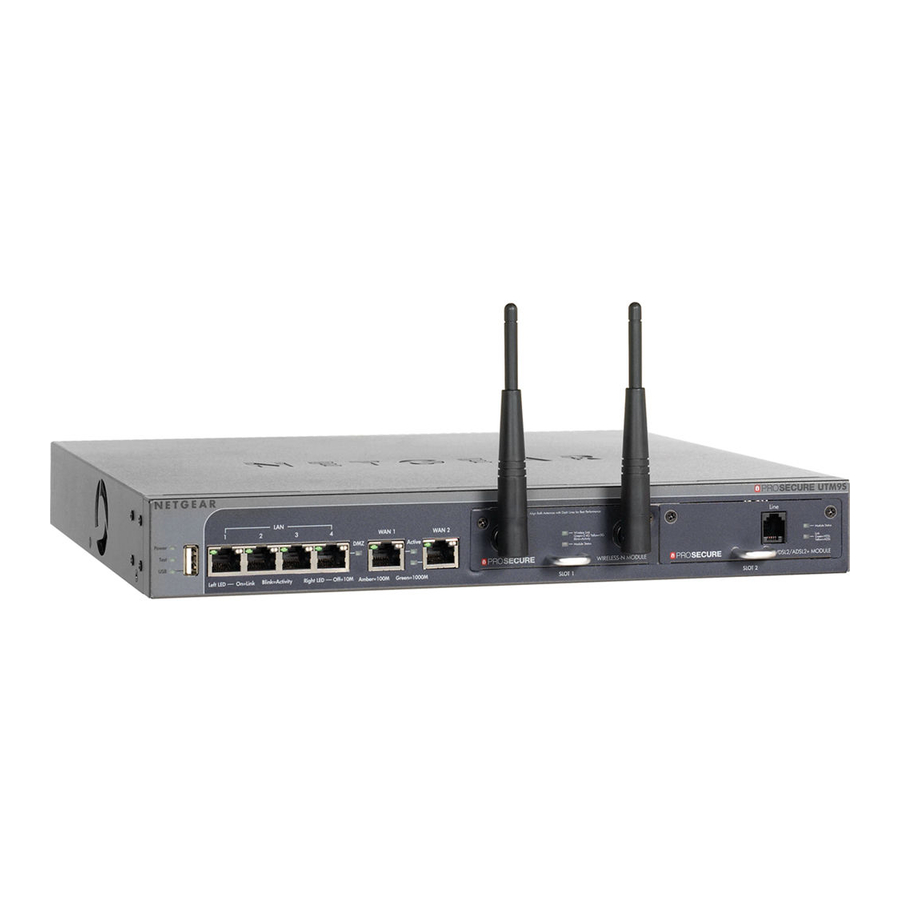
Page 25: Front Panel Utm9S And Modules
Test LED Figure 5. Front panel UTM150 Front Panel UTM9S and Modules Viewed from left to right, the UTM9S front panel contains the following ports and slots: • One nonfunctioning USB port. This port is included for future management enhancements. The port is currently not operable on the UTM9S. - Page 26 Active WAN LEDs Right WAN LEDs USB LED Figure 6. Front panel UTM9S UTM9SDSL xDSL Module The following xDSL modules are available for insertion in one of the UTM9S slots: • UTM9SDSLA. VDSL/ADSL2+ module, Annex A. • UTM9SDSLB. VDSL/ADSL2+ module, Annex B.
-
Page 27: Led Descriptions, Utm5, Utm10, Utm25, Utm50, And Utm150
ProSecure Unified Threat Management (UTM) Appliance Figure 8. UTM9SWLSN wireless module LED Descriptions, UTM5, UTM10, UTM25, UTM50, and UTM150 The following table describes the function of each LED. Table 2. LED descriptions UTM5, UTM10, UTM25, UTM50, and UTM150 Activity Description Power LED On (green) Power is supplied to the UTM. -
Page 28: Led Descriptions, Utm9S And Modules
The WAN port has a valid Internet connection. WAN port models only) LED Descriptions, UTM9S and Modules The following table describes the function of each LED on the UTM9S and the modules. Table 3. LED descriptions UTM9S Activity Description Power LED On (green) Power is supplied to the UTM. - Page 29 The UTM is writing to flash memory (during upgrading or resetting to defaults). The UTM has booted successfully. USB LED Nonfunctioning The USB port is currently not operable on the UTM9S. LAN ports Left LED The LAN port has no link. On (green) The LAN port has detected a link with a connected Ethernet device.
-
Page 30: Rear Panel Utm5, Utm10, And Utm25
ProSecure Unified Threat Management (UTM) Appliance Table 3. LED descriptions UTM9S (continued) Activity Description Wireless The wireless access point is not enabled. Link LED On (green) The wireless access point is enabled in 2.4-GHz operating mode. Blinking (green) There is wireless activity in 2.4-GHz operating mode. -
Page 31: Rear Panel Utm50 And Utm150
Cable security lock receptacle. AC power receptacle. Universal AC input (100–240 VAC, 50–60 Hz). Rear Panel UTM9S Security lock AC power receptacle receptacle Factory Defaults Power reset button switch Console switch Console port Figure 11. Rear panel of the UTM9S Introduction... -
Page 32: Bottom Panels With Product Labels
ProSecure Unified Threat Management (UTM) Appliance Viewed from left to right, the rear panel of the UTM9S contains the following components: Cable security lock receptacle. Factory default Reset button. Using a sharp object, press and hold this button for about 8 seconds until the front panel Test LED flashes to reset the UTM to factory default settings. - Page 33 ProSecure Unified Threat Management (UTM) Appliance The following figure shows the product label for the UTM10: Figure 13. The following figure shows the product label for the UTM25: Figure 14. Introduction...
- Page 34 ProSecure Unified Threat Management (UTM) Appliance The following figure shows the product label for the UTM50: Figure 15. The following figure shows the product label for the UTM150: Figure 16. Introduction...
-
Page 35: Choose A Location For The Utm
ProSecure Unified Threat Management (UTM) Appliance The following figure shows the product label for the UTM9S: Figure 17. Choose a Location for the UTM The UTM is suitable for use in an office environment where it can be freestanding (on its runner feet) or mounted into a standard 19-inch equipment rack. -
Page 36: Use The Rack-Mounting Kit
ProSecure Unified Threat Management (UTM) Appliance Use the Rack-Mounting Kit Use the mounting kit for the UTM to install the appliance in a rack. (A mounting kit is provided in the package for the multiple WAN port models.) Attach the mounting brackets using the hardware that is supplied with the mounting kit. -
Page 37: Steps For Initial Connection
Installation Guide. See the ProSecure Unified Threat Management UTM Installation Guide for complete steps. A PDF of the Installation Guide is on the NETGEAR website at http://www.prosecure.netgear.com/resources/document-library.php. Log in to the UTM. After logging in, you are ready to set up and configure your UTM. See Log In to the UTM on page 38. -
Page 38: Qualified Web Browsers
Qualified Browsers. In the address field, enter https://192.168.1.1. The NETGEAR Configuration Manager Login screen displays in the browser. (The following figure shows the screen for the UTM50.) This screen also provides the User Portal Login Link. For general information about the User... - Page 39 ProSecure Unified Threat Management (UTM) Appliance Figure 19. In the User Name field, type admin. Use lowercase letters. In the Password / Passcode field, type password. Here, too, use lowercase letters. Note: The UTM user name and password are not the same as any user name or password you might use to log in to your Internet connection.
-
Page 40: Web Management Interface Menu Layout
ProSecure Unified Threat Management (UTM) Appliance Figure 20. Web Management Interface Menu Layout The following figure shows the menu at the top the UTM50 web management interface as an example. Option arrow: Additional screen for submenu item 3rd level: Submenu tab (blue) 2nd level: Configuration menu link (gray) 1st level: Main navigation menu link (orange) Figure 21. - Page 41 ProSecure Unified Threat Management (UTM) Appliance The web management interface menu consists of the following components: • 1st level: Main navigation menu links. The main navigation menu in the orange bar across the top of the web management interface provides access to all the configuration functions of the UTM, and remains constant.
-
Page 42: Use The Setup Wizard To Perform The Initial Configuration
Chapter 3, Manually Configuring Internet and WAN Settings. To start the Setup Wizard: Select Wizards from the main navigation menu. The Welcome to the Netgear Configuration Wizard screen displays: Figure 24. Select the Setup Wizard radio button. Click Next. The first Setup Wizard screen displays. -
Page 43: Setup Wizard Step 1 Of 10: Lan Settings
ProSecure Unified Threat Management (UTM) Appliance Setup Wizard Step 1 of 10: LAN Settings Figure 25. Enter the settings as explained in the following table, and then click Next to go the following screen. Note: In this first step, you are actually configuring the LAN settings for the UTM’s default VLAN. - Page 44 ProSecure Unified Threat Management (UTM) Appliance Table 4. Setup Wizard Step 1: LAN Settings screen settings Setting Description LAN TCP/IP Setup IP Address Enter the IP address of the UTM’s default VLAN (the factory default address is 192.168.1.1). Note: Always make sure that the LAN port IP address and DMZ port IP address are in different subnets.
- Page 45 • OU (for organizational unit) • O (for organization) • C (for country) • DC (for domain) For example, to search the Netgear.net domain for all last names of Johnson, you would enter: cn=Johnson,dc=Netgear,dc=net Port The port number for the LDAP server. The default setting is 0 (zero).
-
Page 46: Setup Wizard Step 2 Of 10: Wan Settings
ProSecure Unified Threat Management (UTM) Appliance Table 4. Setup Wizard Step 1: LAN Settings screen settings (continued) Setting Description Inter VLAN Routing Enable Inter VLAN This setting is optional. To ensure that traffic is routed only to VLANs for which Routing inter-VLAN routing is enabled, select the Enable Inter VLAN Routing check box. - Page 47 ProSecure Unified Threat Management (UTM) Appliance Enter the settings as explained in the following table, and then click Next to go the following screen. Note: Instead of manually entering the settings, you can also click the Auto Detect action button at the bottom of the screen. The autodetect process probes the WAN port for a range of connection methods and suggests one that your ISP is most likely to support.
- Page 48 ProSecure Unified Threat Management (UTM) Appliance Table 5. Setup Wizard Step 2: WAN Settings screen settings (continued) Setting Description Other (PPPoE) If you have installed login software such as WinPoET or Enternet, then your connection type is PPPoE. Select this radio button and enter the following settings: Account Name The valid account name for the PPPoE connection.
-
Page 49: Setup Wizard Step 3 Of 10: System Date And Time
ProSecure Unified Threat Management (UTM) Appliance Table 5. Setup Wizard Step 2: WAN Settings screen settings (continued) Setting Description Use Static IP Address If your ISP has assigned you a fixed (static or permanent) IP address, select the Use Static IP Address radio button and enter the following settings. IP Address The static IP address assigned to you. - Page 50 Note: If you select this option but leave either the Server 1 or Server 2 field blank, both fields are set to the default NETGEAR NTP servers. Note: A list of public NTP servers is available at http://support.ntp.org/bin/view/Servers/WebHome.
-
Page 51: Setup Wizard Step 4 Of 10: Services
ProSecure Unified Threat Management (UTM) Appliance Setup Wizard Step 4 of 10: Services Figure 28. Enter the settings as explained in the following table, and then click Next to go the following screen. Table 7. Setup Wizard Step 4: Services screen settings Setting Description Email... - Page 52 ProSecure Unified Threat Management (UTM) Appliance Table 7. Setup Wizard Step 4: Services screen settings (continued) Setting Description HTTP HTTP scanning is enabled by default To disable HTTP scanning, clear the on standard service port 80. corresponding check box. You can change the standard service port or add another port in the corresponding Ports to Scan field.
-
Page 53: Setup Wizard Step 5 Of 10: Email Security
Description SSL Handshaking to Websites Note: SSL handshaking is supported only on the UTM9S. Scanning of Facebook is disabled by default. To enable it, select the Facebook corresponding check box. (This option is not shown in the previous figure, but... - Page 54 • Log only. Only a log entry is created. The email is not blocked, and the attachment is not deleted. • Quarantine attachment (UTM9S only). The email is not blocked, but the attachment is quarantined on a ReadyNAS, and a log entry is created (see the Note on page 176).
-
Page 55: Setup Wizard Step 6 Of 10: Web Security
• Log only. Only a log entry is created. The web file or object is not deleted. • Quarantine file (UTM9S only). The web file or object is quarantined, and a log entry is created (see the Note on page 176). - Page 56 • Log only. Only a log entry is created. The web file or object is not deleted. • Quarantine file (UTM9S only). The web file or object is quarantined, and a log entry is created (see the Note on page 176).
-
Page 57: Setup Wizard Step 7 Of 10: Web Categories To Be Blocked
ProSecure Unified Threat Management (UTM) Appliance Setup Wizard Step 7 of 10: Web Categories to Be Blocked Figure 31. Using the Setup Wizard to Provision the UTM in Your Network... - Page 58 ProSecure Unified Threat Management (UTM) Appliance Enter the settings as explained in the following table, and then click Next to go the following screen. Table 10. Setup Wizard Step 7: Web Categories to be blocked screen settings Setting Description Blocked Web Categories Select the Enable Blocking check box to enable blocking of web categories.
-
Page 59: Setup Wizard Step 8 Of 10: Email Notification
Administrator Email Notification Settings Show as mail sender A descriptive name of the sender for email identification purposes. For example, enter UTM_Notifications@netgear.com. SMTP server The IP address and port number or Internet name and port number of your ISP’s outgoing email SMTP server. The default port number is 25. -
Page 60: Setup Wizard Step 9 Of 10: Signatures & Engine
Update From Set the update source server by selecting one of the following radio buttons: • Default update server. Files are updated from the default NETGEAR update server. • Server address. Files are updated from the server that you specify. Enter the IP address or host name of the update server in the Server address field. -
Page 61: Setup Wizard Step 10 Of 10: Saving The Configuration
ProSecure Unified Threat Management (UTM) Appliance Table 12. Setup Wizard Step 9: Signatures & Engine screen settings (continued) Setting Description Update Frequency Specify the frequency with which the UTM checks for file updates: • Weekly. From the drop-down lists, select the weekday, hour, and minutes that the updates occur. •... -
Page 62: Test Connectivity
Check the downloaded eicar.com test file, and note the attached malware information file. Register the UTM with NETGEAR To receive threat management component updates and technical support, you need to register your UTM with NETGEAR. The UTM is bundled with three 30-day trial licenses: • Web scanning •... - Page 63 To activate the 30-day trial period for a license, do not click Register but click Trial instead. Repeat step 2 step 4 for additional license keys. The UTM activates the licenses and registers the unit with the NETGEAR registration server. Using the Setup Wizard to Provision the UTM in Your Network...
-
Page 64: Electronic Licensing
UTM are no longer displayed on the Registration screen. However, after you have reconfigured the UTM to connect to the Internet and to the NETGEAR registration server, the UTM retrieves and restores all registration information based on its MAC address and hardware serial number. - Page 65 ProSecure Unified Threat Management (UTM) Appliance The UTM is ready for use. However, the following sections describe important tasks that you might want to address before you deploy the UTM in your network: • Configure the WAN Mode (required for the multiple WAN port models). •...
-
Page 66: Chapter 3 Manually Configuring Internet And Wan Settings
DNS, and to configure secondary WAN addresses and advanced WAN options. Note: The Wireless Settings configuration menu is shown on the UTM9S only, accessible under the Network Config main navigation menu. Note: On the UTM9S, the Email Notification configuration menu is accessible under the Monitoring main navigation menu instead of the Network Config main navigation menu. -
Page 67: Internet And Wan Configuration Tasks
For information about configuring the DSL interface of the UTM9S, Appendix A, xDSL Module for the UTM9S. The information in this chapter does also apply to the WAN interfaces of the UTM9S. Generally, five steps are required to complete the WAN Internet connection of your UTM. ... - Page 68 The UTM5 and UTM10 screens show one WAN interface; the UTM25 and UTM50 screens show two WAN interfaces; the UTM150 screen shows four WAN interfaces; the UTM9S screen shows two WAN interfaces and a slot (SLOT-1 or SLOT-2), in which the xDSL module is installed.
- Page 69 ProSecure Unified Threat Management (UTM) Appliance Figure 37. Click the Auto Detect button at the bottom of the screen. The autodetect process probes the WAN port for a range of connection methods and suggests one that your ISP is most likely to support.
- Page 70 ProSecure Unified Threat Management (UTM) Appliance Table 13. Internet connection methods Connection method Manual data input required DHCP (Dynamic IP) No data is required. PPPoE Login, password, account name, and domain name. PPTP Login, password, account name, your IP address, and the server IP address. Fixed (Static) IP IP address, subnet mask, and gateway IP address, and related data supplied by your ISP.
-
Page 71: Set The Utm's Mac Address
ProSecure Unified Threat Management (UTM) Appliance Note: If the configuration process was successful, you are connected to the Internet through the WAN that you just configured. For the multiple WAN port models, continue with the configuration process for the other WAN interfaces. Note: For more information about the WAN Connection Status screen, see View the WAN Ports Status... - Page 72 ProSecure Unified Threat Management (UTM) Appliance Figure 39. In the ISP Login section, select one of the following options: • If your ISP requires an initial login to establish an Internet connection, select Yes. (The default is No.) • If a login is not required, select No, and ignore the Login and Password fields. If you selected Yes, enter the login name in the Login field and the password in the Password field.
- Page 73 ProSecure Unified Threat Management (UTM) Appliance If your connection is PPTP or PPPoE, your ISP requires an initial login. Enter the settings as explained in the following table: Table 14. PPTP and PPPoE settings Setting Description Austria (PPTP) If your ISP is Austria Telecom or any other ISP that uses PPTP for login, select this radio button, and enter the following settings: Account Name The account name is also known as the host name or system name.
- Page 74 ProSecure Unified Threat Management (UTM) Appliance Table 14. PPTP and PPPoE settings (continued) Setting Description Other (PPPoE) Connection Select the Connection Reset check box to specify a time when the (continued) Reset PPPoE WAN connection is reset, that is, the connection is disconnected momentarily and then reestablished.
-
Page 75: Configure The Wan Mode
ProSecure Unified Threat Management (UTM) Appliance In the Domain Name Server (DNS) Servers section of the screen (see the following figure), specify the DNS settings as explained in the following table. Figure 42. Table 16. DNS server settings Setting Description Get Automatically If your ISP has not assigned any Domain Name Server (DNS) addresses, select the from ISP... - Page 76 ProSecure Unified Threat Management (UTM) Appliance Note: For the UTM9S only, you can also use a DSL interface for any of the following modes (see Appendix A, xDSL Module for the UTM9S). • Load balancing mode. The UTM distributes the outbound traffic equally among the WAN interfaces that are functional.
-
Page 77: Configure Network Address Translation (All Models)
ProSecure Unified Threat Management (UTM) Appliance Configure Network Address Translation (All Models) Network Address Translation (NAT) allows all PCs on your LAN to share a single public Internet IP address. From the Internet, there is only a single device (the UTM) and a single IP address. -
Page 78: Configure Auto-Rollover Mode And The Failure Detection Method (Multiple Wan Port Models)
ProSecure Unified Threat Management (UTM) Appliance To configure classical routing: Select Network Config > WAN Settings > WAN Mode. The WAN Mode screen displays (see Figure 43 on page 79). In the NAT (Network Address Translation) section of the screen, select the Classical Routing radio button. - Page 79 ProSecure Unified Threat Management (UTM) Appliance Figure 43. In the Load Balancing Settings section of the screen, configure the following settings: a. Select the Primary WAN Mode radio button. b. From the corresponding drop-down list on the right, select a WAN interface to function as the primary WAN interface.
- Page 80 ProSecure Unified Threat Management (UTM) Appliance Locate the Failure Detection Method section on the screen (see the following figure). Enter the settings as explained in the following table. Figure 44. Table 17. Failure detection method settings Setting Description WAN Failure Detection Method Select a failure detection method from the drop-down list.
-
Page 81: Configure Load Balancing And Optional Protocol Binding
ProSecure Unified Threat Management (UTM) Appliance Note: You can configure the UTM to generate a WAN status log and email this log to a specified address (see Configure Logging, Alerts, and Event Notifications on page 422). Configure Load Balancing and Optional Protocol Binding To use multiple ISP links simultaneously, configure load balancing. - Page 82 ProSecure Unified Threat Management (UTM) Appliance Figure 45. Note: You cannot configure load balancing when you use a PPPoE connection and have selected the Idle Timeout radio button on the WAN ISP Settings screen (single WAN port models) or on one of the WAN ISP Settings screens (multiple WAN port models);...
- Page 83 ProSecure Unified Threat Management (UTM) Appliance Configure Protocol Binding (Optional) To configure protocol binding and add protocol binding rules: Select Network Config > Protocol Binding. The Protocol Bindings screen displays. (The following figure shows two examples in the Protocol Bindings table.) Figure 46.
- Page 84 ProSecure Unified Threat Management (UTM) Appliance Figure 47. Configure the protocol binding settings as explained in the following table: Table 18. Add Protocol Binding screen settings Setting Description Service From the drop-down list, select a service or application to be covered by this rule. If the service or application does not appear in the list, you need to define it using the Services screen (see Service-Based Rules...
-
Page 85: Configure Secondary Wan Addresses
ProSecure Unified Threat Management (UTM) Appliance Click Apply to save your settings. The protocol binding rule is added to the Protocol Bindings table. The rule is automatically enabled, which is indicated by the ! status icon, a green circle. To edit a protocol binding: On the Protocol Bindings screen (see Figure 46... - Page 86 ProSecure Unified Threat Management (UTM) Appliance It is important that you ensure that any secondary WAN addresses are different from the primary WAN, LAN, and DMZ IP addresses that are already configured on the UTM. However, primary and secondary WAN addresses can be in the same subnet. The following is an example of correctly configured IP addresses on a multiple WAN port model: •...
-
Page 87: Configure Dynamic Dns
ProSecure Unified Threat Management (UTM) Appliance Click the Add table button in the rightmost column to add the secondary IP address to the List of Secondary WAN addresses table. Repeat step 4 step 5 for each secondary IP address that you want to add to the List of Secondary WAN addresses table. - Page 88 ProSecure Unified Threat Management (UTM) Appliance To configure DDNS: Select Network Config > Dynamic DNS. The Dynamic DNS screen displays (see the following figure). The WAN Mode section on the screen reports the currently configured WAN mode (for example, Single Port WAN1, Load Balancing, or Auto Rollover). Only those options that match the configured WAN mode are accessible on the screen.
- Page 89 ProSecure Unified Threat Management (UTM) Appliance Figure 50. Access the website of the DDNS service provider, and register for an account (for example, for DynDNS.org, go to http://www.dyndns.com/). Configure the DDNS service settings as explained in the following table: Table 19. DNS service settings Setting Description WAN (Dynamic DNS Status: ...)
-
Page 90: Configure Advanced Wan Options
ProSecure Unified Threat Management (UTM) Appliance Configure Advanced WAN Options The advanced options include configuring the maximum transmission unit (MTU) size, the port speed, and the UTM’s MAC address, and setting a rate limit on the traffic that is being forwarded by the UTM. - Page 91 ProSecure Unified Threat Management (UTM) Appliance Enter the settings as explained in the following table: Table 20. Advanced WAN settings Setting Description MTU Size Make one of the following selections: Default Select the Default radio button for the normal maximum transmit unit (MTU) value.
-
Page 92: Additional Wan-Related Configuration Tasks
If you want the ability to manage the UTM remotely, enable remote management (see Configure Remote Management Access on page 399). If you enable remote management, NETGEAR strongly recommend that you change your password (see Change Passwords and Administrator and Guest Settings on page 397). -
Page 93: Chapter 4 Lan Configuration
Chapter 2, Using the Setup Wizard to Provision the UTM in Your Network. Note: The Wireless Settings configuration menu is shown on the UTM9S only, accessible under the Network Config main navigation menu. Note: On the UTM9S, the Email Notification configuration menu is accessible under the Monitoring main navigation menu instead of the Network Config main navigation menu. -
Page 94: Port-Based Vlans
ProSecure Unified Threat Management (UTM) Appliance A virtual LAN (VLAN) is a local area network with a definition that maps workstations on some basis other than geographic location (for example, by department, type of user, or primary application). To enable traffic to flow between VLANs, traffic needs to go through a router, just as if the VLANs were on two separate LANs. -
Page 95: Assign And Manage Vlan Profiles
ProSecure Unified Threat Management (UTM) Appliance • When a port receives an untagged packet, this packet is forwarded to a VLAN based on the PVID. • When a port receives a tagged packet, this packet is forwarded to a VLAN based on the ID that is extracted from the tagged packet. -
Page 96: Vlan Dhcp Options
ProSecure Unified Threat Management (UTM) Appliance Figure 52. For each VLAN profile, the following fields display in the VLAN Profiles table: • Check box. Allows you to select the VLAN profile in the table. • Status icon. Indicates the status of the VLAN profile: Green circle. - Page 97 ProSecure Unified Threat Management (UTM) Appliance DHCP Server The default VLAN (VLAN 1) has the DHCP server option enabled by default, allowing the UTM to assign IP, DNS server, WINS server, and default gateway addresses to all computers connected to the UTM’s LAN. The assigned default gateway address is the LAN address of the UTM.
-
Page 98: Configure A Vlan Profile
For each VLAN on the UTM, you can configure its profile, port membership, LAN TCP/IP settings, DHCP options, DNS server, and inter-VLAN routing capability. The preconfigured default VLAN is called defaultVLAN. A UTM9S in which a wireless module is installed also has a default WLAN with the name defaultWLAN. - Page 99 ProSecure Unified Threat Management (UTM) Appliance Either select an entry from the VLAN Profiles table and click the corresponding Edit table button, or add a new VLAN profile by clicking the Add table button under the VLAN Profiles table. The Edit VLAN Profile screen displays. The following figure shows the Edit VLAN Profile screen for the UTM with four ports in the Port Membership section.
- Page 100 You can enter VLAN IDs from 2 to 4093. VLAN ID 1 is reserved for the default VLAN; VLAN ID 4094 is reserved for the DMZ interface. Port Membership UTM5, UTM9S, UTM10, UTM25, and UTM150: Select one, several, or all port check boxes to make the ports members of this Port 1, Port 2, Port 3, VLAN.
- Page 101 ProSecure Unified Threat Management (UTM) Appliance Table 21. Edit VLAN Profile screen settings (continued) Setting Description Enable DHCP Server Select the Enable DHCP Server radio button to enable the UTM to function as a Dynamic Host Configuration Protocol (DHCP) server, providing TCP/IP configuration for all computers connected to the VLAN.
- Page 102 • OU (for organizational unit) • O (for organization) • C (for country) • DC (for domain) For example, to search the Netgear.net domain for all last names of Johnson, you would enter: cn=Johnson,dc=Netgear,dc=net Port The port number for the LDAP server. The default setting is 0 (zero).
-
Page 103: Configure Vlan Mac Addresses And Advanced Lan Settings
ProSecure Unified Threat Management (UTM) Appliance Note: When you have completed the LAN setup, all outbound traffic is allowed and all inbound traffic is discarded except responses to requests from the LAN side. For information about how to change these default traffic rules, see Chapter 5, Firewall Protection. -
Page 104: Configure Multihome Lan Ips On The Default Vlan
ProSecure Unified Threat Management (UTM) Appliance Figure 55. From the MAC Address for VLANs drop-down list, select Unique. (The default is Same.) As an option, you can disable the broadcast of ARP packets for the default VLAN by clearing the Enable ARP Broadcast check box. (The broadcast of ARP packets is enabled by default for the default VLAN.) If you choose to keep the broadcast of ARP enabled, you can enter an ARP refresh rate in the Set Refresh Rate field. - Page 105 ProSecure Unified Threat Management (UTM) Appliance The following is an example of correctly configured IP addresses on a multiple WAN port model: • WAN1 IP address. 10.0.0.1 with subnet 255.0.0.0 • WAN2 IP address. 20.0.0.1 with subnet 255.0.0.0 • DMZ IP address. 192.168.10.1 with subnet 255.255.255.0 •...
-
Page 106: Manage Groups And Hosts (Lan Groups)
ProSecure Unified Threat Management (UTM) Appliance To edit a secondary LAN IP address: On the LAN Multi-homing screen (see the previous screen), click the Edit button in the Action column for the secondary IP address that you want to modify. The Edit Secondary LAN IP address screen displays. -
Page 107: Manage The Network Database
ProSecure Unified Threat Management (UTM) Appliance These are some advantages of the network database: • Generally, you do not need to enter an IP address or a MAC address. Instead, you can just select the name of the desired PC or device. •... - Page 108 ProSecure Unified Threat Management (UTM) Appliance Figure 57. The Known PCs and Devices table lists the entries in the network database. For each PC or device, the following fields display: • Check box. Allows you to select the PC or device in the table. •...
- Page 109 ProSecure Unified Threat Management (UTM) Appliance Add PCs or Devices to the Network Database To add PCs or devices manually to the network database: In the Add Known PCs and Devices section of the LAN Groups screen (see the previous figure), enter the settings as explained in the following table: Table 22.
-
Page 110: Change Group Names In The Network Database
ProSecure Unified Threat Management (UTM) Appliance Figure 58. Modify the settings as explained in Table 22 on page 109. Click Apply to save your settings in the Known PCs and Devices table. Deleting PCs or Devices from the Network Database ... -
Page 111: Set Up Address Reservation
ProSecure Unified Threat Management (UTM) Appliance Figure 59. Select the radio button next to the group name that you want to edit. Type a new name in the field. The maximum number of characters is 15; spaces and double quotes (") are not allowed. Repeat step 3 step 4... -
Page 112: Configure And Enable The Dmz Port
ProSecure Unified Threat Management (UTM) Appliance Configure and Enable the DMZ Port The demilitarized zone (DMZ) is a network that, by default, has fewer firewall restrictions than the LAN. The DMZ can be used to host servers (such as a web server, FTP server, or email server) and provide public access to them. - Page 113 ProSecure Unified Threat Management (UTM) Appliance Figure 60. Enter the settings as explained in the following table: Table 23. DMZ Setup screen settings Setting Description DMZ Port Setup Do you want to Select one of the following radio buttons: enable DMZ Port? •...
- Page 114 ProSecure Unified Threat Management (UTM) Appliance Table 23. DMZ Setup screen settings (continued) Setting Description DHCP Disable DHCP Server If another device on your network is the DHCP server for the VLAN, or if you will manually configure the network settings of all of your computers, select the Disable DHCP Server radio button to disable the DHCP server.
-
Page 115: Manage Routing
• OU (for organizational unit) • O (for organization) • C (for country) • DC (for domain) For example, to search the Netgear.net domain for all last names of Johnson, you would enter: cn=Johnson,dc=Netgear,dc=net Port The port number for the LDAP server. The default setting is 0 (zero). -
Page 116: Configure Static Routes
ProSecure Unified Threat Management (UTM) Appliance Internet access, and you do not need to configure additional static routes. You should configure static routes only for unusual cases such as multiple firewalls or multiple IP subnets located on your network. Note: The UTM automatically sets up routes between VLANs and secondary IP addresses that you have configured on the LAN Multi-homing screen (see... - Page 117 ProSecure Unified Threat Management (UTM) Appliance Enter the settings as explained in the following table: Table 24. Add Static Route screen settings Setting Description Route Name The route name for the static route (for purposes of identification and management). Active To make the static route effective, select the Active check box.
-
Page 118: Configure Routing Information Protocol
ProSecure Unified Threat Management (UTM) Appliance Configure Routing Information Protocol Routing Information Protocol (RIP), RFC 2453, is an Interior Gateway Protocol (IGP) that is commonly used in internal networks (LANs). RIP enables a router to exchange its routing information automatically with other routers, to dynamically adjust its routing tables, and to adapt to changes in the network. - Page 119 ProSecure Unified Threat Management (UTM) Appliance Enter the settings as explained in the following table: Table 25. RIP Configuration screen settings Setting Description RIP Direction From the RIP Direction drop-down list, select the direction in which the UTM sends and receives RIP packets: •...
-
Page 120: Static Route Example
ProSecure Unified Threat Management (UTM) Appliance Table 25. RIP Configuration screen settings (continued) Setting Description Authentication for Not Valid Before The beginning of the lifetime of the MD5 key. Enter the month, RIP-2B/2M required? date, year, hour, minute, and second. Before this date and (continued) time, the MD5 key is not valid. -
Page 121: Chapter 5 Firewall Protection
Use the Intrusion Prevention System Note: The IGMP submenu tab shows on the Firewall configuration menu of the UTM9S only. About Firewall Protection A firewall protects one network (the trusted network, such as your LAN) from another (the untrusted network, such as the Internet), while allowing communication between the two. -
Page 122: Administrator Tips
ProSecure Unified Threat Management (UTM) Appliance Administrator Tips Consider the following operational items: As an option, you can enable remote management if you have to manage distant sites from a central location (see Configure Authentication Domains, Groups, and Users page 345 and Configure Remote Management Access on page 399). -
Page 123: Service-Based Rules
ProSecure Unified Threat Management (UTM) Appliance The firewall rules for blocking and allowing traffic on the UTM can be applied to LAN WAN traffic, DMZ WAN traffic, and LAN DMZ traffic. Table 26. Number of supported firewall rule configurations Traffic rule Maximum number of Maximum number of Maximum number of... - Page 124 ProSecure Unified Threat Management (UTM) Appliance The following table describes the fields that define the rules for outbound traffic and that are common to most Outbound Service screens (see Figure 66 on page 132, Figure 69 page 135, and Figure 72 on page 138).
- Page 125 ProSecure Unified Threat Management (UTM) Appliance Table 27. Outbound rules overview (continued) Setting Description WAN Users The settings that determine which Internet locations are covered by the rule, based on their IP address. The options are: • Any. All Internet IP address are covered by this rule. •...
- Page 126 ProSecure Unified Threat Management (UTM) Appliance Table 27. Outbound rules overview (continued) Setting Description The setting that determines whether packets covered by this rule are logged. The options are: • Always. Always log traffic considered by this rule, whether it matches or not. This is useful when you are debugging your rules.
- Page 127 ProSecure Unified Threat Management (UTM) Appliance Note: The UTM always blocks denial of service (DoS) attacks. A DoS attack does not attempt to steal data or damage your PCs, but overloads your Internet connection so you cannot use it (that is, the service becomes unavailable).
- Page 128 ProSecure Unified Threat Management (UTM) Appliance Table 28. Inbound rules overview (continued) Setting Description Select Schedule The time schedule (that is, Schedule1, Schedule2, or Schedule3) that is used by this rule. • This drop-down list is activated only when BLOCK by schedule, otherwise allow or ALLOW by schedule, otherwise block is selected as the action.
- Page 129 ProSecure Unified Threat Management (UTM) Appliance Table 28. Inbound rules overview (continued) Setting Description DMZ Users The settings that determine which DMZ computers on the DMZ network are affected by this rule. The options are: • Any. All PCs and devices on your DMZ network. •...
-
Page 130: Order Of Precedence For Rules
ProSecure Unified Threat Management (UTM) Appliance Order of Precedence for Rules As you define a new rule, it is added to a table in a Rules screen as the last item in the list, as shown in the LAN WAN Rules screen example in the following figure: Figure 64. - Page 131 ProSecure Unified Threat Management (UTM) Appliance Next to the drop-down list, click the Apply table button. Figure 65. To make changes to an existing outbound or inbound service rule, in the Action column to the right of to the rule, click one of the following table buttons: •...
- Page 132 ProSecure Unified Threat Management (UTM) Appliance LAN WAN Outbound Service Rules You can define rules that specify exceptions to the default rules. By adding custom rules, you can block or allow access based on the service or application, source or destination IP addresses, and time of day.
-
Page 133: Set Dmz Wan Rules
ProSecure Unified Threat Management (UTM) Appliance To create a new inbound LAN WAN service rule: In the LAN WAN Rules screen, click the Add table button under the Inbound Services table. The Add LAN WAN Inbound Service screen displays: Figure 67. - Page 134 ProSecure Unified Threat Management (UTM) Appliance To access the DMZ WAN Rules screen, select Network Security > Firewall > DMZ WAN Rules. The DMZ WAN Rules screen displays. (The following figure shows a rule in the Outbound Services table as an example.) Figure 68.
- Page 135 ProSecure Unified Threat Management (UTM) Appliance can block or allow traffic between the DMZ and any external WAN IP address according to the schedule created in the Schedule screen. To create a new outbound DMZ WAN service rule: In the DMZ WAN Rules screen, click the Add table button under the Outbound Services table.
-
Page 136: Set Lan Dmz Rules
ProSecure Unified Threat Management (UTM) Appliance Figure 70. Enter the settings as explained in Table 28 on page 127. Click Apply to save your changes. The new rule is now added to the Inbound Services table. Set LAN DMZ Rules The LAN DMZ Rules screen allows you to create rules that define the movement of traffic between the LAN and the DMZ. - Page 137 ProSecure Unified Threat Management (UTM) Appliance Figure 71. In the Action column to the right of to the rule, click one of the following table buttons: • Edit. Allows you to make any changes to the rule definition of an existing rule. Depending on your selection, either the Edit LAN DMZ Outbound Service screen (identical to Figure 72 on page 138) or the Edit LAN DMZ Inbound Service screen (identical to...
- Page 138 ProSecure Unified Threat Management (UTM) Appliance Figure 72. Enter the settings as explained in Table 27 on page 124. Click Apply. The new rule is now added to the Outbound Services table. The rule is automatically enabled. LAN DMZ Inbound Service Rules The Inbound Services table lists all existing rules for inbound traffic.
-
Page 139: Inbound Rule Examples
ProSecure Unified Threat Management (UTM) Appliance Enter the settings as explained in Table 28 on page 127. Click Apply to save your changes. The new rule is now added to the Inbound Services table. Inbound Rule Examples LAN WAN Inbound Rule: Host a Local Public Web Server If you host a public web server on your local network, you can define a rule to allow inbound web (HTTP) requests from any outside IP address to the IP address of your web server at any time of the day. - Page 140 LAN. The following addressing scheme is used to illustrate this procedure: • NETGEAR UTM: WAN IP address. 10.1.0.118 LAN IP address subnet. 192.168.1.1 with subnet 255.255.255.0 DMZ IP address subnet. 192.168.10.1 with subnet 255.255.255.0 •...
- Page 141 ProSecure Unified Threat Management (UTM) Appliance Tip: If you arrange with your ISP to have more than one public IP address for your use, you can use the additional public IP addresses to map to servers on your LAN or DMZ. One of these public IP addresses is used as the primary IP address of the router that provides Internet access to your LAN PCs through NAT.
- Page 142 ProSecure Unified Threat Management (UTM) Appliance For the multiple WAN port models only: From the WAN Destination IP Address drop-down list, select the web server (the simulated 10.1.0.52 address in this example) that you have defined on a WAN Secondary Addresses screen (see Configure Secondary WAN Addresses on page 85).
-
Page 143: Outbound Rule Example
ProSecure Unified Threat Management (UTM) Appliance WARNING! For security, NETGEAR strongly recommends that you avoid creating an exposed host. When a computer is designated as the exposed host, it loses much of the protection of the firewall and is exposed to many exploits from the Internet. If compromised, the computer can be used to attack your network. -
Page 144: Configure Other Firewall Features
ProSecure Unified Threat Management (UTM) Appliance Configure Other Firewall Features You can configure global VLAN rules and attack checks, set session limits, and manage the application level gateway (ALG) for SIP sessions. VLAN Rules The VLAN Rules screen allows you to specify inter-VLAN firewall rules (that is, firewall rules for VLANs that are created on the UTM) when inter-VLAN routing is not enabled (see Configure a VLAN Profile on page 98). - Page 145 ProSecure Unified Threat Management (UTM) Appliance Enter the settings as explained in the following table. Table 29. Add VLAN-VLAN Service screen settings Setting Description Service The service or application to be covered by this rule. If the service or application does not display in the list, you need to define it using the Services screen (see Add Customized Services on page 152).
-
Page 146: Attack Checks, Vpn Pass-Through, And Multicast Pass-Through
The various types of attack checks are listed on the Attack Checks screen and defined in Table 30 on page 147. The configuration of multicast pass-through for the UTM9S is different from the other UTM models; see Configure Multicast Pass-through (UTM9S Only) on page 148. - Page 147 ProSecure Unified Threat Management (UTM) Appliance Enter the settings as explained in the following table: Table 30. Attack Checks screen settings Setting Description WAN Security Checks Respond to Ping on Select the Respond to Ping on Internet Ports check box to enable the UTM to Internet Ports respond to a ping from the Internet.
- Page 148 • L2TP. Disables NAT filtering for L2TP tunnels. By default, all three check boxes are selected. Multicast Pass through Note: This section is not displayed on the Attacks screen for the UTM9S. For the UTM9S, see the next section, Configure Multicast Pass-through (UTM9S Only).
- Page 149 (IGMP) proxy is enabled for the upstream (WAN) and downstream (LAN) interfaces. This proxy allows the UTM9S to forward relevant multicast traffic from the WAN to the LAN, and to keep track of the IGMP group membership when LAN hosts join or leave the multicast group.
-
Page 150: Set Session Limits
ProSecure Unified Threat Management (UTM) Appliance To delete one or more multicast source addresses: In the Alternate Networks table, select the check box to the left of each address that you want to delete, or click the Select All table button to select all addresses. Click the Delete table button. -
Page 151: Manage The Application Level Gateway For Sip Sessions
ProSecure Unified Threat Management (UTM) Appliance Table 31. Session Limit screen settings (continued) Setting Description User Limit Enter a number to indicate the user limit. If the User Limit Parameter is set to Percentage of Max Sessions, the number specifies the maximum number of sessions that are allowed from a single-source device as a percentage of the total session connection capacity of the UTM. -
Page 152: Create Services, Qos Profiles, And Bandwidth Profiles
ProSecure Unified Threat Management (UTM) Appliance Create Services, QoS Profiles, and Bandwidth Profiles When you create inbound and outbound firewall rules, you use firewall objects such as services, service groups, IP groups (LAN and WAN groups), QoS profiles, bandwidth profiles, and schedules to narrow down the firewall rules: •... - Page 153 ProSecure Unified Threat Management (UTM) Appliance To define a new service, you need to determine first which port number or range of numbers is used by the application. You can usually determine this information by contacting the publisher of the application, user groups, or newsgroups. When you have the port number information, you can enter it on the Services screen.
-
Page 154: Create Service Groups
ProSecure Unified Threat Management (UTM) Appliance Table 32. Services screen settings (continued) Setting Description Start Port The first TCP or UDP port of a range that the service uses. Note: This field is enabled only when you select TCP or UDP from the Type drop-down list. End Port The last TCP or UDP port of a range that the service uses. - Page 155 ProSecure Unified Threat Management (UTM) Appliance One advantage of a service group is that you can create a single firewall object with multiple noncontiguous ports (for example ports 3000, 4000, and 5000) and apply the object in a single firewall rule. For example, if there are 10 web servers, each of which requires the same three port-forwarding rules, you can create a service group for the port-forwarding rules, an IP group for the web servers (see Create IP Groups...
-
Page 156: Create Ip Groups
ProSecure Unified Threat Management (UTM) Appliance To edit a service group: In the Custom Services Group table, click the Edit table button to the right of the service group that you want to edit. The Edit Service group screen displays. Modify the settings that you wish to change (see step 3 step 4... - Page 157 ProSecure Unified Threat Management (UTM) Appliance Figure 90. In the IP Address fields, type an IP address. Click the Add table button to add the IP address to the IP Addresses Grouped table. Repeat the previous two steps to add more IP addresses to the IP Addresses Grouped table.
-
Page 158: Create Quality Of Service Profiles
ProSecure Unified Threat Management (UTM) Appliance Create Quality of Service Profiles A Quality of Service (QoS) profile defines the relative priority of an IP packet when multiple connections are scheduled for simultaneous transmission on the UTM. A QoS profile becomes active only when it is associated with a nonblocking inbound or outbound firewall rule, and traffic matching the firewall rule is processed by the UTM. - Page 159 ProSecure Unified Threat Management (UTM) Appliance Figure 91. The screen displays the List of QoS Profiles table with the user-defined profiles. Under the List of QoS Profiles table, click the Add table button. The Add QoS Profile screen displays: Figure 92. Enter the settings as explained in the following table.
-
Page 160: Create Bandwidth Profiles
ProSecure Unified Threat Management (UTM) Appliance Table 33. Add QoS Profile screen settings (continued) Setting Description From the QoS drop-down list, select one of the following traffic classification methods: • IP Precedence. A legacy method that sets the priority in the ToS byte of an IP header. - Page 161 ProSecure Unified Threat Management (UTM) Appliance interface that you specify. For inbound traffic, you can apply bandwidth profiles to a LAN interface for all WAN modes. Bandwidth profiles do not apply to the DMZ interface. When a new connection is established by a device, the device locates the firewall rule corresponding to the connection.
- Page 162 ProSecure Unified Threat Management (UTM) Appliance Figure 94. Enter the settings as explained in the following table: Table 34. Add Bandwidth Profile screen settings Setting Description Profile Name A descriptive name of the bandwidth profile for identification and management purposes. Direction From the Direction drop-down list, select the traffic direction for the bandwidth profile: •...
-
Page 163: Set A Schedule To Block Or Allow Specific Traffic
ProSecure Unified Threat Management (UTM) Appliance Table 34. Add Bandwidth Profile screen settings (continued) Setting Description Type From the Type drop-down list, select the type for the bandwidth profile: • Group. The profile applies to all users, that is, all users share the available bandwidth. -
Page 164: Enable Source Mac Filtering
ProSecure Unified Threat Management (UTM) Appliance Figure 95. In the Scheduled Days section, select one of the following radio buttons: • All Days. The schedule is in effect all days of the week. • Specific Days. The schedule is in effect only on specific days. To the right of the radio buttons, select the check box for each day that you want the schedule to be in effect. - Page 165 ProSecure Unified Threat Management (UTM) Appliance Note: For additional ways of restricting outbound traffic, see Outbound Rules (Service Blocking) on page 123. To enable MAC filtering and add MAC addresses to be permitted or blocked: Select Network Security > Address Filter. The Address Filter submenu tabs display, with the Source MAC Filter screen in view.
-
Page 166: Set Up Ip/Mac Bindings
ProSecure Unified Threat Management (UTM) Appliance To remove one or more entries from the table: Select the check box to the left of each MAC address that you want to delete, or click the Select All table button to select all entries. Click the Delete table button. - Page 167 ProSecure Unified Threat Management (UTM) Appliance To set up IP/MAC bindings: Select Network Security > Address Filter > IP/MAC Binding. The IP/MAC Binding screen displays. (The following figure shows some bindings in the IP/MAC Binding table as an example.) Figure 97.
-
Page 168: Configure Port Triggering
ProSecure Unified Threat Management (UTM) Appliance Table 35. IP/MAC Binding screen settings (continued) Setting Description IP Address The IP address of the PC or device that is bound to the MAC address. Log Dropped To log the dropped packets, select Enable from the drop-down list. The default setting Packets is Disable. - Page 169 ProSecure Unified Threat Management (UTM) Appliance Note these restrictions on port triggering: • Only one PC can use a port-triggering application at any time. • After a PC has finished using a port-triggering application, there is a short time-out period before the application can be used by another PC.
- Page 170 ProSecure Unified Threat Management (UTM) Appliance Table 36. Port Triggering screen settings (continued) Setting Description Outgoing (Trigger) Start Port The start port (1–65534) of the range for triggering. Port Range End Port The end port (1–65534) of the range for triggering. Incoming (Response) Start Port The start port (1–65534) of the range for responding.
-
Page 171: Configure Universal Plug And Play
ProSecure Unified Threat Management (UTM) Appliance Configure Universal Plug and Play The Universal Plug and Play (UPnP) feature enables the UTM to automatically discover and configure devices when it searches the LAN and WAN. Select Security > UPnP. The UPnP screen displays: Figure 100. -
Page 172: Use The Intrusion Prevention System
ProSecure Unified Threat Management (UTM) Appliance Use the Intrusion Prevention System The Intrusion Prevention System (IPS) of the UTM monitors all network traffic to detect, in real time, network attacks and port scans and to protect your network from such intrusions. You can set up alerts, block source IP addresses from which port scans are initiated, and drop traffic that carries attacks. - Page 173 ProSecure Unified Threat Management (UTM) Appliance When you enable the IPS, the default IPS configuration goes into effect. The default IPS configuration is the configuration that the Advanced screen returns to when you click the factory default reset button. To modify the default IPS configuration: Select Network Security >...
- Page 174 ProSecure Unified Threat Management (UTM) Appliance In the Enabled column for each section, either select individual attacks by selecting the check boxes to the left of the names, or select all attacks for that category by selecting the top leftmost check box to the left of All web attacks. In the Action column for each section, either select the actions for individual attacks by making selections from the drop-down lists to the right of the names, or select a global action for all attacks for that category by making a selection from the top drop-down list.
-
Page 175: Chapter 6 Content Filtering And Optimizing Scans
Content Filtering and Optimizing Scans This chapter describes how to apply the content-filtering features of the UTM and how to optimize scans to protect your network. This chapter contains the following sections: • About Content Filtering and Scans • Configure Email Protection •... -
Page 176: Default Email And Web Scan Settings
ProSecure Unified Threat Management (UTM) Appliance Note: The UTM9S can quarantine spam and malware only if you have integrated a ReadyNAS (see Connect to a ReadyNAS on page 415) and configured the quarantine settings (see Configure the Quarantine Settings on page 416). - Page 177 Allowed Tools Alexa Toolbar Allowed GoToMyPC Allowed Weatherbug Allowed Yahoo Toolbar Allowed SSL Handshaking to Websites Note: SSL handshaking is supported on the UTM9S only. Facebook Allowed Web objects Embedded Objects (ActiveX/Java/Flash Allowed Javascript Allowed Proxy Allowed Cookies Allowed Web content categories...
-
Page 178: Configure Email Protection
ProSecure Unified Threat Management (UTM) Appliance Table 38. Default email and web scan settings (continued) Scan type Default scan setting Default action (if applicable) Politics and Religion Allowed Sexual Content Blocked Technology Allowed a. Files or messages that are larger than 2048 KB are skipped by default. Configure Email Protection The UTM lets you configure the following settings to protect the network’s email communication:... -
Page 179: Customize Email Antivirus And Notification Settings
ProSecure Unified Threat Management (UTM) Appliance In the Email section of the screen, select the protocols to scan by selecting the Enable check boxes, and enter the port numbers if different from the default port numbers: • SMTP. Simple Mail Transfer Protocol (SMTP) scanning is enabled by default on port 25. - Page 180 ProSecure Unified Threat Management (UTM) Appliance Figure 104. Content Filtering and Optimizing Scans...
- Page 181 • Log only. Only a log entry is created. The email is not blocked, and the attachment is not deleted. • Quarantine attachment (UTM9S only). The email is not blocked, but the attachment is quarantined on a ReadyNAS, and a log entry is created (see the Note on page 176).
- Page 182 ProSecure Unified Threat Management (UTM) Appliance Table 39. Email Anti-Virus screen settings (continued) Setting Description Notification Settings Insert Warning into For SMTP email messages, select this check box to insert a warning into the email Email Subject (SMTP) subject line: •...
-
Page 183: Email Content Filtering
ProSecure Unified Threat Management (UTM) Appliance Table 39. Email Anti-Virus screen settings (continued) Setting Description Subject The default subject line for the notification email is Malware detected! You can change this subject line. Message The warning message informs the sender, the recipient, or both about the name of the malware threat. - Page 184 ProSecure Unified Threat Management (UTM) Appliance Figure 105. Enter the settings as explained in the following table: Table 40. Email Filters screen settings Setting Description Filter by Subject Keywords Keywords Enter keywords that should be detected in the email subject line. Use commas to separate different keywords.
- Page 185 ProSecure Unified Threat Management (UTM) Appliance Table 40. Email Filters screen settings (continued) Setting Description Action SMTP From the SMTP drop-down list, select one of the following actions when a keyword that is defined in the Keywords field is detected: •...
-
Page 186: Protect Against Email Spam
Real-time blacklist. Emails from known spam sources that are collected by blacklist providers are blocked. Distributed spam analysis. Emails that are detected as spam by the NETGEAR Spam Classification Center are either tagged or blocked. This order of implementation ensures the optimum balance between spam prevention and system performance. - Page 187 ProSecure Unified Threat Management (UTM) Appliance Note: Emails that are processed through the UTM over an authenticated email connection between a client and a mail server are not checked for spam. Note: An email that has been checked for spam by the UTM contains an X-STM-SMTP (for SMTP emails) or X-STM-POP3 (for POP-3 emails) tag in its header.
- Page 188 ProSecure Unified Threat Management (UTM) Appliance Figure 106. Content Filtering and Optimizing Scans...
- Page 189 ProSecure Unified Threat Management (UTM) Appliance Enter the settings as explained in the following table: Table 41. Whitelist/Blacklist screen settings Setting Description Sender IP Address (SMTP Only) Whitelist Enter the source IP addresses from which emails can be trusted. Blacklist Enter the source IP addresses from which emails are blocked.
- Page 190 ProSecure Unified Threat Management (UTM) Appliance By default, the UTM comes with three pre-defined blacklist providers: Dsbl, Spamhaus, and Spamcop. There is no limit to the number of blacklist providers that you can add to the RBL sources. To enable the real-time blacklist: Select Application Security >...
- Page 191 Note: Unlike other scans, you do not need to configure the spam score because the NETGEAR Spam Classification Center performs the scoring automatically as long as the UTM is connected to the Internet. However, this does mean that the UTM needs to be connected to the Internet for the spam analysis to be performed correctly.
- Page 192 ProSecure Unified Threat Management (UTM) Appliance Figure 108. The UTM9S also has a Send Quarantine Spam Report section at the bottom of the Distributed Spam Analysis screen: Figure 109. Enter the settings as explained in the following table: Table 42. Distributed Spam Analysis screen settings...
- Page 193 Anti-Spam Engine Settings Use a proxy Select this check box if the UTM connects to the Netgear Spam Classification Center (also server to referred to as the Detection Center) over a proxy server. Then specify the following connect to information.
-
Page 194: Configure Web And Services Protection
This option is supported on the UTM9S only (see the Note on page 176). Enable To enable the UTM9S to automatically email a spam report, select the Enable check box, and specify when the reports should be sent. Specify when the reports should be sent by selecting one of the following radio buttons: •... - Page 195 ProSecure Unified Threat Management (UTM) Appliance HTTP, but not HTTPS (if this last protocol is not often used). For more information about performance, see Performance Management on page 389. To configure the web protocols, ports, and applications to scan: Select Application Security >...
- Page 196 ProSecure Unified Threat Management (UTM) Appliance Note: For information about email protocols and ports, see Customize Email Protocol Scan Settings on page 178. Table 43. Services screen settings Setting Description HTTP Select the HTTP check box to enable Hypertext Transfer Protocol (HTTP) scanning.
-
Page 197: Configure Web Malware Scans
Winamp (Internet Radio/TV) SSL Handshaking to Websites Note: SSL handshaking is supported on the UTM9S only. (This option is not shown in the previous figure.) Scanning of Facebook is disabled by default. To enable it, select the Facebook corresponding check box. - Page 198 • Log only. Only a log entry is created. The web file or object is not deleted. • Quarantine file (UTM9S only). The web file or object is quarantined, and a log entry is created (see the Note on page 176).
-
Page 199: Configure Web Content Filtering
176, all requested traffic from any website is allowed. You can specify a message such as Blocked by NETGEAR that is displayed onscreen if a LAN user attempts to access a blocked site (see the Notification Settings section that is described at the bottom of Table 45 on page 203). - Page 200 ProSecure Unified Threat Management (UTM) Appliance The following are keyword blocking examples: If the keyword XXX is specified, the URL www.zzyyqq.com/xxx.html is blocked, as is the newsgroup alt.pictures.XXX. If the keyword .com is specified, only websites with other domain suffixes (such as .edu or .gov) can be viewed.
- Page 201 ProSecure Unified Threat Management (UTM) Appliance Note: You can bypass any type of web blocking for trusted URLs by adding the URLs to the whitelist (see Configure Web URL Filtering on page 206). Access to the URLs on the whitelist is allowed for PCs in the groups for which file extension, keyword, object, or category blocking, or a combination of these types of web blocking has been enabled.
- Page 202 ProSecure Unified Threat Management (UTM) Appliance Figure 113. Content filtering, screen 2 of 3 Content Filtering and Optimizing Scans...
- Page 203 ProSecure Unified Threat Management (UTM) Appliance Figure 114. Content filtering, screen 3 of 3 Enter the settings as explained in the following table: Table 45. Content Filtering screen settings Setting Description Content Filtering Log HTTP Traffic Select this check box to log HTTP traffic. For information about how to view the logged traffic, see Query the Logs on page 460.
- Page 204 ProSecure Unified Threat Management (UTM) Appliance Table 45. Content Filtering screen settings (continued) Setting Description Block Files with By default, the File Extension field lists the most common file extensions. You can the Following manually add or delete extensions. Use commas to separate different extensions. You Extensions can enter a maximum of 40 file extensions.
- Page 205 ProSecure Unified Threat Management (UTM) Appliance Table 45. Content Filtering screen settings (continued) Setting Description Select the Web Categories You Wish to Block Select the Enable Blocking check box to enable blocking of web categories. (By default, this check box is selected.) Select the check boxes of any web categories that you want to block.
-
Page 206: Configure Web Url Filtering
Lookup Results. If the URL appears to be uncategorized, you can submit it to NETGEAR for analysis. Submit to To submit an uncategorized URL to NETGEAR for analysis, select the category in NETGEAR which you think that the URL needs to be categorized from the drop-down list. Then click the Submit button. - Page 207 ProSecure Unified Threat Management (UTM) Appliance To configure web URL filtering: Select Application Security > HTTP/HTTPS > URL Filtering. The URL Filtering screen displays. The following figure shows some URLs as examples: Figure 115. Content Filtering and Optimizing Scans...
- Page 208 ProSecure Unified Threat Management (UTM) Appliance Enter the settings as explained in the following table: Table 46. URL Filtering screen settings Setting Description Whitelist Enable Select this check box to bypass scanning of the URLs that are listed in the URL field.
-
Page 209: Https Scan Settings
ProSecure Unified Threat Management (UTM) Appliance Table 46. URL Filtering screen settings (continued) Setting Description Delete To delete one or more URLs, highlight the URLs, and click the Delete (continued) table button. Export To export the URLs, click the Export table button, and follow the instructions of your browser. - Page 210 ProSecure Unified Threat Management (UTM) Appliance Figure 116. The HTTPS scanning process functions with the following principles: • The UTM breaks up an SSL connection between an HTTPS server and an HTTP client in two parts: A connection between the HTTPS client and the UTM A connection between the UTM and the HTTPS server •...
- Page 211 ProSecure Unified Threat Management (UTM) Appliance Figure 117. However, even when a certificate is trusted or still valid, or when the name of a certificate does match the name of the website, a security alert message still displays when a user who is connected to the UTM visits an HTTPS site.
- Page 212 ProSecure Unified Threat Management (UTM) Appliance Figure 118. Enter the settings as explained in the following table: Table 47. HTTPS Settings screen settings Setting Description HTTP Tunneling Select this check box to allow scanning of HTTPS connections through an HTTP proxy, which is disabled by default.
-
Page 213: Manage Digital Certificates For Https Scans
ProSecure Unified Threat Management (UTM) Appliance Table 47. HTTPS Settings screen settings (continued) Setting Description HTTPS SSL Settings Select the Allow the UTM to handle HTTPS connections using SSLv2 check box to allow HTTPS connections using SSLv2, SSLv3, or TLSv1. If this check box is cleared, the UTM allows HTTPS connections using SSLv3 or TLSv1, but not using SSLv2. - Page 214 ProSecure Unified Threat Management (UTM) Appliance Figure 119. The UTM contains a self-signed certificate from NETGEAR. This certificate can be downloaded from the UTM login screen or from the Certificate Management screen for browser import. However, before you deploy the UTM in your network, NETGEAR...
- Page 215 Follow the instructions of your browser to save the RootCA.crt file on your computer. To reload the default NETGEAR certificate: Select the Use NETGEAR default certificate radio button. Click Apply to save your settings. To import a new certificate: Select the Use imported certificate (PKCS12 format) radio button.
- Page 216 ProSecure Unified Threat Management (UTM) Appliance Click the Upload button. Note: If the certificate file is not in the pkcs12 format, the upload fails. Importing a new certificate overwrites any previously imported certificates. Click Apply to save your settings. Manage Trusted HTTPS Certificates To manage trusted certificates, select Web Security >...
- Page 217 ProSecure Unified Threat Management (UTM) Appliance To view details of a trusted certificate: From the Trusted Certificates table, select the certificate. Click View Details. A new screen opens that displays the details of the certificate. To delete a trusted certificate: From the Trusted Certificates table, select the certificate.
-
Page 218: Specify Trusted Hosts
ProSecure Unified Threat Management (UTM) Appliance Specify Trusted Hosts You can specify trusted hosts for which the UTM bypasses HTTPS traffic scanning and security certificate authentication. The security certificate is sent directly to the client for authentication, which means that the user does not receive a security alert for trusted hosts. For more information about security alerts, see Manage Self-Signed Certificates page 384. -
Page 219: Configure Ftp Scans
ProSecure Unified Threat Management (UTM) Appliance Table 48. Trusted Hosts screen settings (continued) Setting Description Hosts This field contains the trusted hosts for which scanning is bypassed. To add a host to this field, use the Add Host field or the Import from File tool (see the explanation later in this table). You can add a maximum of 200 URLs. - Page 220 • Log only. Only a log entry is created. The FTP file or object is not deleted. • Quarantine file (UTM9S only). The FTP file or object is quarantined, and a log entry is created (see the Note on page 176).
-
Page 221: Set Web Access Exception Rules
ProSecure Unified Threat Management (UTM) Appliance Table 49. FTP screen settings (continued) Setting Description Block Files with the Following Extensions By default, the File Extension field lists the most common file extensions. You can manually add or delete extensions. Use commas to separate different extensions. You can enter a maximum of 40 file extensions. The maximum total length of this field, excluding the delimiter commas, is 160 characters. - Page 222 ProSecure Unified Threat Management (UTM) Appliance Note: Users and groups to which access exception rules apply are not the same as LAN groups. For information about how to specify members of a LAN group and to customize LAN group names, see Configure Authentication Domains, Groups, and Users on page 345.
- Page 223 ProSecure Unified Threat Management (UTM) Appliance Figure 125. Under the Exceptions table, click the Add table button to specify an exception rule. The Add or Edit or Block/Accept Exceptions screen displays: Figure 126. Content Filtering and Optimizing Scans...
- Page 224 ProSecure Unified Threat Management (UTM) Appliance Complete the fields and make your selections from the drop-down lists as explained in the following table: Table 50. Edit or Block/Accept Exceptions screen settings Setting Description Action From the drop-down list, select the action that the UTM applies: •...
- Page 225 ProSecure Unified Threat Management (UTM) Appliance Table 50. Edit or Block/Accept Exceptions screen settings (continued) Setting Description Domain Unauthenticated Click the Apply button to apply the exception to all unauthenticated users. User/Group These are users who have not actively logged in to the UTM. By default, (continued) these users are assigned the account name anonymous.
- Page 226 ProSecure Unified Threat Management (UTM) Appliance Table 50. Edit or Block/Accept Exceptions screen settings (continued) Setting Description Domain Custom Groups Do the following: User/Group 1. From the Name drop-down list, select a custom group. (continued) 2. Click the Apply button to apply the exception to the selected group. You can specify custom groups on the Custom Groups screen (see Create Custom Groups for Web Access Exceptions on page 228).
- Page 227 ProSecure Unified Threat Management (UTM) Appliance Table 50. Edit or Block/Accept Exceptions screen settings (continued) Setting Description Category URL Filtering The action applies to a URL. The following radio buttons, field, and (and related drop-down list display onscreen. Select a radio button to either enter a information) URL expression or select a custom URL list.
-
Page 228: Create Custom Groups For Web Access Exceptions
ProSecure Unified Threat Management (UTM) Appliance • Enable. Enables the rule or rules. The ! status icon changes from a gray circle to a green circle, indicating that the rule is or rules are enabled. • Delete. Deletes the rule or rules. The table rank of the exception rule in the Exceptions table determines the order in which the rule is applied (from the top down). - Page 229 ProSecure Unified Threat Management (UTM) Appliance Figure 128. Complete the fields and make your selections from the drop-down lists as explained in the following table: Table 51. Custom Groups screen settings Setting Description Name A name of the custom group for identification and management purposes. Brief A description of the custom group for identification and management purposes.
- Page 230 ProSecure Unified Threat Management (UTM) Appliance Table 51. Custom Groups screen settings (continued) Setting Description Local Groups Do the following: Users/Groups 1. From the Name drop-down list, select a local group. to this group 2. Click the Add button to add the selected local group to the custom group.
-
Page 231: Create Custom Categories For Web Access Exceptions
ProSecure Unified Threat Management (UTM) Appliance Table 51. Custom Groups screen settings (continued) Setting Description RADIUS User Do the following: Users/Groups 1. From the Domain drop-down list, select a RADIUS domain. to this group 2. From the VLAN ID/Name drop-down list, select a VLAN ID or VLAN (continued) name. - Page 232 ProSecure Unified Threat Management (UTM) Appliance Figure 129. Under the Custom Categories table, click the Add table button to specify a custom category. The Add Custom Category screen displays. The nature of the screen depends on your selection from the Category Type drop-down list, which is set by default to Applications (this selection is shown in the following figure).
- Page 233 ProSecure Unified Threat Management (UTM) Appliance Figure 131. Custom categories: URL filtering Figure 132. Custom categories: web categories Content Filtering and Optimizing Scans...
- Page 234 ProSecure Unified Threat Management (UTM) Appliance Complete the fields and make your selections from the drop-down lists as explained in the following table: Table 52. Custom Categories screen settings Setting Description Name A name of the custom category for identification and management purposes. Brief A description of the category group for identification and management purposes.
-
Page 235: Set Scanning Exclusions
ProSecure Unified Threat Management (UTM) Appliance Table 52. Custom Categories screen settings (continued) Setting Description Category Type URL Filtering Import from File field: (continued) (continued) To import a list with URLs into the URLs in this Category field, click the Browse button and navigate to a file in .txt format that contains line-delimited URLs (that is, one URL per line). - Page 236 ProSecure Unified Threat Management (UTM) Appliance server do not need to be scanned. To prevent the UTM from scanning these files, you can configure a scanning exclusion for your web server. To configure scanning exclusion rules: Select Application Security > Scanning Exclusions. The Scanning Exclusions screen displays.
-
Page 237: Chapter 7 Virtual Private Networking Using Ipsec Connections
Your WAN mode selection impacts how the VPN features need to be configured. Note: For the UTM9S only, you can also use a DSL interface in combination with a WAN interface for VPN tunnel failover. - Page 238 ProSecure Unified Threat Management (UTM) Appliance The use of fully qualified domain names (FQDNs) in VPN policies is mandatory when the WAN ports function in auto-rollover mode or load balancing mode, and is also required for VPN tunnel failover. When the WAN ports function in load balancing mode, you cannot configure VPN tunnel failover.
-
Page 239: Use The Ipsec Vpn Wizard For Client And Gateway Configurations
Configurations You can use the IPSec VPN Wizard to configure multiple gateway or client VPN tunnel policies. The following section provides wizard and NETGEAR ProSafe VPN Client software configuration procedures for the following scenarios: • Using the wizard to configure a VPN tunnel between two VPN gateways •... - Page 240 ProSecure Unified Threat Management (UTM) Appliance To set up a gateway-to-gateway VPN tunnel using the VPN Wizard: Select VPN > IPSec VPN > VPN Wizard. The VPN Wizard screen displays (see the following figure, which shows the VPN Wizard screen for the UTM50, and contains an example).
- Page 241 ProSecure Unified Threat Management (UTM) Appliance Figure 138. Select the radio buttons and complete the fields and as explained in the following table: Table 55. IPSec VPN Wizard settings for a gateway-to-gateway tunnel Setting Description About VPN Wizard This VPN tunnel will connect Select the Gateway radio button.
- Page 242 ProSecure Unified Threat Management (UTM) Appliance Table 55. IPSec VPN Wizard settings for a gateway-to-gateway tunnel (continued) Setting Description End Point Information What is the Remote WAN’s IP Enter the IP address or Internet name (FQDN) of the WAN interface on the Address or Internet Name? remote VPN tunnel endpoint.
-
Page 243: Create A Client-To-Gateway Vpn Tunnel
Activate the IPSec VPN connection: a. Select Monitoring > Active Users & VPNs > IPSec VPN Connection Status. The IPSec VPN Connection Status screen displays. (The UTM9S also shows the PPTP Active Users and L2TP Active Users tabs.) Figure 140. - Page 244 Use the VPN Wizard to Configure the Gateway for a Client Tunnel on page 244. • Use the NETGEAR VPN Client Wizard to Create a Secure Connection on page 246 or Manually Create a Secure Connection Using the NETGEAR VPN Client on page 251.
- Page 245 ProSecure Unified Threat Management (UTM) Appliance Select the radio buttons and complete the fields and as explained in the following table: Table 56. IPSec VPN Wizard settings for a client-to-gateway tunnel Setting Description About VPN Wizard This VPN tunnel will connect Select the VPN Client radio button.
- Page 246 Router’s LAN network mask 255.255.255.0 Router’s WAN IP address 10.34.116.22 Use the NETGEAR VPN Client Wizard to Create a Secure Connection The VPN client lets you set up the VPN connection manually (see Manually Create a Secure Connection Using the NETGEAR VPN Client on page 251) or with the integrated Configuration Wizard, which is the easier and preferred method.
- Page 247 ProSecure Unified Threat Management (UTM) Appliance Note: Perform these tasks from a PC that has the NETGEAR ProSafe VPN Client installed. To use the Configuration Wizard to set up a VPN connection between the VPN client and the UTM: Right-click the VPN client icon in your Windows system tray, and select Configuration Panel.
- Page 248 ProSecure Unified Threat Management (UTM) Appliance Figure 145. Select the A router or a VPN gateway radio button, and click Next. The VPN tunnel parameters wizard screen (screen 2 of 3) displays. Figure 146. Specify the following VPN tunnel parameters: •...
- Page 249 ProSecure Unified Threat Management (UTM) Appliance Click Next. The Configuration Summary wizard screen (screen 3 of 3) displays. Figure 147. This screen is a summary screen of the new VPN configuration. Click Finish. Specify the local and remote IDs: a. In the tree list pane of the Configuration Panel screen, click Gateway (the default name given to the authentication phase).
- Page 250 ProSecure Unified Threat Management (UTM) Appliance c. Specify the settings that are explained in the following table. Table 58. VPN client advanced authentication settings Setting Description Advanced features Aggressive Mode Select this check box to enable aggressive mode as the mode of negotiation with the UTM.
- Page 251 Manually Create a Secure Connection Using the NETGEAR VPN Client Note: Perform these tasks from a PC that has the NETGEAR ProSafe VPN Client installed. To manually configure a VPN connection between the VPN client and the UTM, create authentication settings (phase 1 settings), create an associated IPSec configuration (phase 2 settings), and then specify the global parameters.
- Page 252 ProSecure Unified Threat Management (UTM) Appliance Configure the Authentication Settings (Phase 1 Settings) To create new authentication settings: Right-click the VPN client icon in your Windows system tray, and select Configuration Panel. The Configuration Panel screen displays. Figure 150. In the tree list pane of the Configuration Panel screen, right-click VPN Configuration, and select New Phase 1.
- Page 253 ProSecure Unified Threat Management (UTM) Appliance Note: This is the name for the authentication phase that is used only for the VPN client, not during IKE negotiation. You can view and change this name in the tree list pane. This name needs to be a unique name. The Authentication pane displays in the Configuration Panel screen, with the Authentication tab selected by default.
- Page 254 ProSecure Unified Threat Management (UTM) Appliance Click Apply to use the new settings immediately, and click Save to keep the settings for future use. Click the Advanced tab in the Authentication pane. The Advanced pane displays. Figure 153. Specify the settings that are explained in the following table. Table 60.
- Page 255 ProSecure Unified Threat Management (UTM) Appliance Table 60. VPN client advanced authentication settings (continued) Setting Description Local and Remote ID Local ID As the type of ID, select DNS from the Local ID drop-down list because you specified FQDN in the UTM configuration. As the value of the ID, enter utm_remote.com as the local ID for the VPN client.
- Page 256 ProSecure Unified Threat Management (UTM) Appliance Figure 154. Specify the settings that are explained in the following table. Table 61. VPN client IPSec configuration settings Setting Description VPN Client address Either enter 0.0.0.0 as the IP address, or enter a virtual IP address that is used by the VPN client in the UTM’s LAN;...
- Page 257 ProSecure Unified Threat Management (UTM) Appliance Table 61. VPN client IPSec configuration settings (continued) Setting Description Encryption Select 3DES as the encryption algorithm from the drop-down list. Authentication Select SHA-1 as the authentication algorithm from the drop-down list. Mode Select Tunnel as the encapsulation mode from the drop-down list. PFS and Group Select the PFS check box, and then select the DH2 (1024) key group from the drop-down list.
-
Page 258: Test The Connection And View Connection And Status Information
Test the Connection and View Connection and Status Information Both the NETGEAR ProSafe VPN Client and the UTM provide VPN connection and status information. This information is useful for verifying the status of a connection and troubleshooting problems with a connection. - Page 259 ProSecure Unified Threat Management (UTM) Appliance • Use the Connection Panel screen. On the main menu of the Configuration Panel screen, select Tools > Connection Panel to open the Connection Panel screen. Perform one of the following tasks: Double-click Gateway-Tunnel. Right-click Gateway-Tunnel, and select Open tunnel.
-
Page 260: Netgear Vpn Client Status And Log Information
To review the status of current IPSec VPN tunnels, select Monitoring > Active Users & VPNs > IPSec VPN Connection Status. The IPSec VPN Connection Status screen displays. (The following figure shows an IPSec SA as an example. The UTM9S also shows the PPTP Active Users and L2TP Active Users tabs.) Figure 162. -
Page 261: View The Utm Ipsec Vpn Log
ProSecure Unified Threat Management (UTM) Appliance The Active IPSec SA(s) table lists each active connection with the information that is described in the following table. The default poll interval is 5 seconds. To change the poll interval period, enter a new value in the Poll Interval field, and then click the Set Interval button. -
Page 262: Manage Ipsec Vpn Policies
ProSecure Unified Threat Management (UTM) Appliance Manage IPSec VPN Policies After you have used the VPN Wizard to set up a VPN tunnel, a VPN policy and an IKE policy are stored in separate policy tables. The name that you selected as the VPN tunnel connection name during the VPN Wizard setup identifies both the VPN policy and IKE policy. - Page 263 ProSecure Unified Threat Management (UTM) Appliance IKE Policies Screen To access the IKE Policies screen: Select VPN > IPSec VPN. The IPSec VPN submenu tabs display with the IKE Policies screen in view. (The following figure shows some examples.) Figure 164.
- Page 264 ProSecure Unified Threat Management (UTM) Appliance To delete one or more IKE polices: Select the check box to the left of each policy that you want to delete, or click the Select All table button to select all IKE policies. Click the Delete table button.
- Page 265 ProSecure Unified Threat Management (UTM) Appliance Figure 165. Virtual Private Networking Using IPSec Connections...
- Page 266 ProSecure Unified Threat Management (UTM) Appliance Complete the fields, select the radio buttons, and make your selections from the drop-down lists as explained in the following table: Table 64. Add IKE Policy screen settings Setting Description Mode Config Record Do you want to use Specify whether or not the IKE policy uses a Mode Config record.
- Page 267 • SHA-1. Hash algorithm that produces a 160-bit digest. This is the default setting. • MD5. Hash algorithm that produces a 128-bit digest. • AES-256 (UTM9S only). AES with a 256-bit key size. • AES-512 (UTM9S only). AES with a 512-bit key size. Virtual Private Networking Using IPSec Connections...
- Page 268 • Group 1 (768 bit). • Group 2 (1024 bit). This is the default setting. • Group 5 (1536 bit). • Group 14 (2048 bit) (UTM9S only). • Group 15 (3072 bit) (UTM9S only). • Group 16 (4096 bit) (UTM9S only).
-
Page 269: Manage Vpn Policies
ProSecure Unified Threat Management (UTM) Appliance Table 64. Add IKE Policy screen settings (continued) Setting Description Extended Authentication XAUTH Configuration Select one of the following radio buttons to specify whether or not Extended Authentication (XAUTH) is enabled, and, if enabled, which device is used to verify user account information: Note: For more... - Page 270 ProSecure Unified Threat Management (UTM) Appliance • Manual. You manually enter all settings (including the keys) for the VPN tunnel on the UTM and on the remote VPN endpoint. No third-party server or organization is involved. • Auto. Some settings for the VPN tunnel are generated automatically through the use of the IKE (Internet Key Exchange) Protocol to perform negotiations between the two VPN endpoints (the local ID endpoint and the remote ID endpoint).
- Page 271 ProSecure Unified Threat Management (UTM) Appliance Each policy contains the data that are explained in the following table. These fields are explained in more detail in Table 66 on page 273. Table 65. List of VPN Policies table information Setting Description ! (Status) Indicates whether the policy is enabled (green circle) or disabled (gray circle).
- Page 272 ProSecure Unified Threat Management (UTM) Appliance Manually Add or Edit a VPN Policy To manually add a VPN policy: Select VPN > IPSec VPN > VPN Policies. The VPN Policies screen displays (see Figure 166 on page 270). Under the List of VPN Policies table, click the Add table button. The Add VPN Policy screen displays (see the following figure, which shows the UTM50 screen).
- Page 273 ProSecure Unified Threat Management (UTM) Appliance Complete the fields, select the radio buttons and check boxes, and make your selections from the drop-down lists as explained in the following table: Table 66. Add New VPN Policy screen settings Setting Description General Policy Name A descriptive name of the VPN policy for identification and management...
- Page 274 ProSecure Unified Threat Management (UTM) Appliance Table 66. Add New VPN Policy screen settings (continued) Setting Description Enable Keepalive Select a radio button to specify if keep-alive is enabled: • Yes. This feature is enabled: Periodically, the UTM sends keep-alive requests (ping packets) to the remote endpoint to keep the tunnel alive.
- Page 275 • SHA-1. Hash algorithm that produces a 160-bit digest. This is the default setting. • MD5. Hash algorithm that produces a 128-bit digest. • SHA-256 (UTM9S only). Hash algorithm that produces a 256-bit key size. • SHA-512 (UTM9S only). Hash algorithm that produces a 512-bit key size. Key-In The integrity key for the inbound policy.
- Page 276 • SHA-1. Hash algorithm that produces a 160-bit digest. This is the default setting. • MD5. Hash algorithm that produces a 128-bit digest. • AES-256 (UTM9S only). Hash algorithm that produces a 256-bit digest. • AES-512 (UTM9S only). Hash algorithm that produces a 512-bit digest. PFS Key Group Select this check box to enable Perfect Forward Secrecy (PFS), and then select a Diffie-Hellman (DH) group from the drop-down list.
-
Page 277: Configure Extended Authentication (Xauth)
ProSecure Unified Threat Management (UTM) Appliance In the List of VPN Policies table, click the Edit table button to the right of the VPN policy that you want to edit. The Edit VPN Policy screen displays. This screen shows the same fields as the Add VPN Policy screen (see Figure 167 on page 272). -
Page 278: User Database Configuration
ProSecure Unified Threat Management (UTM) Appliance To enable and configure XAUTH: Select VPN > IPSec VPN. The IPSec VPN submenu tabs display with the IKE Policies screen in view (see Figure 164 on page 263). In the List of IKE Policies table, click the Edit table button to the right of the IKE policy for which you want to enable and configure XAUTH. -
Page 279: Radius Client Configuration
ProSecure Unified Threat Management (UTM) Appliance RADIUS Client Configuration Remote Authentication Dial In User Service (RADIUS, RFC 2865) is a protocol for managing authentication, authorization, and accounting (AAA) of multiple users in a network. A RADIUS server stores a database of user information and can validate a user at the request of a gateway or server in the network when a user requests access to network resources. - Page 280 ProSecure Unified Threat Management (UTM) Appliance Table 68. RADIUS Client screen settings (continued) Setting Description Secret Phrase A shared secret phrase to authenticate the transactions between the client and the primary RADIUS server. The same secret phrase needs to be configured on both the client and the server.
-
Page 281: Assign Ip Addresses To Remote Users (Mode Config)
ProSecure Unified Threat Management (UTM) Appliance Assign IP Addresses to Remote Users (Mode Config) To simplify the process of connecting remote VPN clients to the UTM, use the Mode Config feature to automatically assign IP addresses to remote users, including a network access IP address, subnet mask, WINS server, and DNS address. - Page 282 ProSecure Unified Threat Management (UTM) Appliance Figure 169. As an example, the screen shows two Mode Config records with the names EMEA Sales and NA Sales: • For EMEA Sales, a first pool (172.16.100.1 through 172.16.100.99) and second pool (172.16.200.1 through 172.16.200.99) are shown. •...
- Page 283 ProSecure Unified Threat Management (UTM) Appliance Figure 170. Complete the fields, select the check box, and make your selections from the drop-down lists as explained in the following table: Table 69. Add Mode Config Record screen settings Setting Description Client Pool Record Name A descriptive name of the Mode Config record for identification and management purposes.
- Page 284 ProSecure Unified Threat Management (UTM) Appliance Table 69. Add Mode Config Record screen settings (continued) Setting Description WINS Server If there is a WINS server on the local network, enter its IP address in the Primary field. You can enter the IP address of a second WINS server in the Secondary field. DNS Server Enter the IP address of the DNS server that is used by remote VPN clients in the Primary field.
- Page 285 ProSecure Unified Threat Management (UTM) Appliance Select VPN > IPSec VPN. The IPSec VPN submenu tabs display with the IKE Policies screen in view (see Figure 164 on page 263). Under the List of IKE Policies table, click the Add table button. The Add IKE Policy screen displays.
- Page 286 ProSecure Unified Threat Management (UTM) Appliance Note: The IKE policy settings that are explained in the following table are specifically for a Mode Config configuration. Table 64 on page 266 explains the general IKE policy settings. Table 70. IKE policy settings for a Mode Config configuration Setting Description Mode Config Record...
- Page 287 The period in seconds for which the IKE SA is valid. When the period times out, the next rekeying occurs. The default setting is 28800 seconds (8 hours). However, for a Mode Config configuration, NETGEAR recommends 3600 seconds (1 hour). Enable Dead Peer...
-
Page 288: Configure The Prosafe Vpn Client For Mode Config Operation
ProSecure Unified Threat Management (UTM) Appliance Table 70. IKE policy settings for a Mode Config configuration (continued) Setting Description Extended Authentication XAUTH Configuration Select one of the following radio buttons to specify whether or not Extended Authentication (XAUTH) is enabled, and, if enabled, which device is used to verify user account information: Note: For more... - Page 289 ProSecure Unified Threat Management (UTM) Appliance Note: Perform these tasks from a PC that has the NETGEAR ProSafe VPN Client installed. To configure the VPN client for Mode Config operation, create authentication settings (phase 1 settings), create an associated IPSec configuration (phase 2 settings), and then specify the global parameters.
- Page 290 ProSecure Unified Threat Management (UTM) Appliance Figure 173. Change the name of the authentication phase (the default is Gateway): a. Right-click the authentication phase name. b. Select Rename. c. Type GW_ModeConfig. d. Click anywhere in the tree list pane. Note: This is the name for the authentication phase that is used only for the VPN client, not during IKE negotiation.
- Page 291 ProSecure Unified Threat Management (UTM) Appliance Specify the settings that are explained in the following table. Table 71. VPN client authentication settings (Mode Config) Setting Description Interface Select Any from the drop-down list. Remote Gateway Enter the remote IP address or DNS name of the UTM. For example, enter 10.34.116.22.
- Page 292 ProSecure Unified Threat Management (UTM) Appliance Specify the settings that are explained in the following table. Table 72. VPN client advanced authentication settings (Mode Config) Setting Description Advanced features Mode Config Select this check box to enable Mode Config. Aggressive Mode Select this check box to enable aggressive mode as the mode of negotiation with the UTM.
- Page 293 ProSecure Unified Threat Management (UTM) Appliance Note: This is the name for the IPSec configuration that is used only for the VPN client, not during IPSec negotiation. You can view and change this name in the tree list pane. This name needs to be a unique name. The IPSec pane displays in the Configuration Panel screen, with the IPSec tab selected by default.
- Page 294 ProSecure Unified Threat Management (UTM) Appliance Table 73. VPN client IPSec configuration settings (Mode Config) (continued) Setting Description Subnet mask Enter 255.255.255.0 as the remote subnet mask of the UTM that opens the VPN tunnel. This is the LAN IP subnet mask that you specified in the Local Subnet Mask field on the Add Mode Config Record screen of the UTM.
-
Page 295: Test The Mode Config Connection
ProSecure Unified Threat Management (UTM) Appliance Specify the following default lifetimes in seconds to match the configuration on the UTM: • Authentication (IKE), Default. Enter 3600 seconds. • Encryption (IPSec), Default. Enter 3600 seconds. Select the Dead Peer Detection (DPD) check box, and configure the following DPD settings to match the configuration on the UTM: •... -
Page 296: Modify Or Delete A Mode Config Record
ProSecure Unified Threat Management (UTM) Appliance Figure 180. From the client PC, ping a computer on the UTM LAN. Modify or Delete a Mode Config Record Note: Before you modify or delete a Mode Config record, make sure it is not used in an IKE policy. -
Page 297: Configure Keep-Alives And Dead Peer Detection
ProSecure Unified Threat Management (UTM) Appliance Configure Keep-Alives and Dead Peer Detection In some cases, you might not want a VPN tunnel to be disconnected when traffic is idle, for example, when client-server applications over the tunnel cannot tolerate the tunnel establishment time. -
Page 298: Configure Dead Peer Detection
ProSecure Unified Threat Management (UTM) Appliance Enter the settings as explained in the following table: Table 74. Keep-alive settings Setting Description General Enable Keepalive Select the Yes radio button to enable the keep-alive feature. Periodically, the UTM sends keep-alive requests (ping packets) to the remote endpoint to keep the tunnel alive. -
Page 299: Configure Netbios Bridging With Ipsec Vpn
ProSecure Unified Threat Management (UTM) Appliance Figure 182. In the IKE SA Parameters section of the screen, locate the DPD fields, and complete the fields as explained the following table: Table 75. Dead peer Detection settings Setting Description IKE SA Parameters Enable Dead Peer Select the Yes radio button to enable DPD. -
Page 300: Configure The Pptp Server (Utm9S Only)
PPTP client that is located behind the UTM9S. You need to enable the PPTP server on the UTM9S, specify a PPTP server address pool, and create PPTP user accounts. For information about how to create PPTP user accounts, Configure User Accounts on page 362. - Page 301 ProSecure Unified Threat Management (UTM) Appliance Figure 184. Enter the settings as explained in the following table: Table 76. PPTP Server screen settings Setting Description PPTP Server Enable PPTP Server To enable the PPTP server, select the Enable check box. Complete the following fields: Start IP Address Type the first IP address of the address pool.
-
Page 302: View The Active Pptp Users
Remote IP The remote client’s IP address. L2TP IP The IP address that is assigned by the PPTP server on the UTM9S. Action This column is not applicable to PPTP. The default poll interval is 5 seconds. To change the poll interval period, enter a new value in the Poll Interval field, and then click the Set Interval button. -
Page 303: Configure The L2Tp Server (Utm9S Only)
L2TP. (Packets that traverse the L2TP tunnel are not encapsulated by IPSec or MPPE.) You need to enable the L2TP server on the UTM9S, specify an L2TP server address pool, and create L2TP user accounts. For information about how to create L2TP user accounts, Configure User Accounts on page 362. -
Page 304: View The Active L2Tp Users
ProSecure Unified Threat Management (UTM) Appliance Enter the settings as explained in the following table: Table 78. L2TP Server screen settings Setting Description L2TP Server Enable L2TP Server To enable the L2TP server, select the Enable check box. Complete the following fields: Start IP Address Type the first IP address of the address pool. - Page 305 Remote IP The client’s IP address on the remote LAC. L2TP IP The IP address that is assigned by the L2TP server on the UTM9S. Action This column is not applicable to L2TP. The default poll interval is 5 seconds. To change the poll interval period, enter a new value in the Poll Interval field, and then click the Set Interval button.
-
Page 306: Chapter 8 Virtual Private Networking Using Ssl Connections
Virtual Private Networking Using SSL Connections The UTM provides a hardware-based SSL VPN solution designed specifically to provide remote access for mobile users to their corporate resources, bypassing the need for a preinstalled VPN client on their computers. Using the familiar Secure Sockets Layer (SSL) protocol, commonly used for e-commerce transactions, the UTM can authenticate itself to an SSL-enabled client, such as a standard web browser. -
Page 307: Use The Ssl Vpn Wizard For Client Configurations
Configure and Edit SSL Connections on page 323. To start the SSL VPN Wizard: Select Wizards from the main navigation menu. The Welcome to the Netgear Configuration Wizard screen displays: Figure 188. Select the SSL VPN Wizard radio button. -
Page 308: Ssl Vpn Wizard Step 1 Of 6 (Portal Settings)
ProSecure Unified Threat Management (UTM) Appliance SSL VPN Wizard Step 1 of 6 (Portal Settings) Figure 189. Note that the previous figure contains a layout example. Enter the settings as explained in the following table, and then click Next to go the following screen. Note: If you leave the Portal Layout Name field blank, the SSL VPN Wizard uses the default portal layout. - Page 309 <meta http-equiv=”pragma” content=”no-cache”> <meta http-equiv=”cache-control” content=”no-cache”> <meta http-equiv=”cache-control” content=”must-revalidate”> Note: NETGEAR strongly recommends enabling HTTP meta tags for security reasons and to prevent out-of-date web pages, themes, and data being stored in a user’s web browser cache. ActiveX web Select this check box to enable ActiveX cache control to be loaded when users log in to the cache cleaner SSL VPN portal.
-
Page 310: Ssl Vpn Wizard Step 2 Of 6 (Domain Settings)
ProSecure Unified Threat Management (UTM) Appliance Table 80. SSL VPN Wizard Step 1 of 6 screen settings (portal settings) (continued) Setting Description SSL VPN Portal Pages to Display VPN Tunnel page To provide full network connectivity, select this check box. Port Forwarding To provide access to specific defined network services, select this check box. - Page 311 ProSecure Unified Threat Management (UTM) Appliance Note: If you leave the Domain Name field blank, the SSL VPN Wizard uses the default domain name geardomain. You need to enter a name other than geardomain in the Domain Name field to enable the SSL VPN Wizard to create a new domain.
- Page 312 ProSecure Unified Threat Management (UTM) Appliance Table 81. SSL VPN Wizard Step 2 of 6 screen settings (domain settings) (continued) Setting Description Authentication Type • WIKID-CHAP. WiKID Systems CHAP. Complete the following fields: (continued) - Authentication Server - Authentication Secret - Radius Port - Repeat - Timeout...
- Page 313 ProSecure Unified Threat Management (UTM) Appliance Table 81. SSL VPN Wizard Step 2 of 6 screen settings (domain settings) (continued) Setting Description Portal The portal that you selected on the first SSL VPN Wizard screen. You cannot change the portal on this screen; the portal is displayed for information only. Authentication Server The server IP address or server name of the authentication server for any type of authentication other than authentication through the local user database.
-
Page 314: Ssl Vpn Wizard Step 3 Of 6 (User Settings)
ProSecure Unified Threat Management (UTM) Appliance Table 81. SSL VPN Wizard Step 2 of 6 screen settings (domain settings) (continued) Setting Description Group Members This field is optional. The attribute that is used to identify the members of a group. Attribute For an Active Directory, enter member. - Page 315 ProSecure Unified Threat Management (UTM) Appliance Note: Do not enter an existing user name in the User Name field; otherwise, the SSL VPN Wizard will fail and the UTM will reboot to recover its configuration. Table 82. SSL VPN Wizard Step 3 of 6 screen settings (user settings) Setting Description User Name...
-
Page 316: Ssl Vpn Wizard Step 4 Of 6 (Client Addresses And Routes)
ProSecure Unified Threat Management (UTM) Appliance SSL VPN Wizard Step 4 of 6 (Client Addresses and Routes) Figure 192. Note that the previous figure contains an example. Enter the settings as explained in the following table, and then click Next to go the following screen. Note: Do not enter an existing route for a VPN tunnel client in the Destination Network and Subnet Mask fields;... -
Page 317: Ssl Vpn Wizard Step 5 Of 6 (Port Forwarding)
ProSecure Unified Threat Management (UTM) Appliance Table 83. SSL VPN Wizard Step 4 of 6 screen settings (client addresses and routes) (continued) Setting Description Primary DNS Server The IP address of the primary DNS server that is assigned to the VPN tunnel clients. - Page 318 ProSecure Unified Threat Management (UTM) Appliance Note: Do not enter an IP address that is already in use in the upper Local Server IP Address field or a port number that is already in use in the TCP Port Number field; otherwise, the SSL VPN Wizard will fail and the UTM will reboot to recover its configuration.
-
Page 319: Ssl Vpn Wizard Step 6 Of 6 (Verify And Save Your Settings)
ProSecure Unified Threat Management (UTM) Appliance For more information about port-forwarding settings, see Configure Applications for Port Forwarding on page 328. SSL VPN Wizard Step 6 of 6 (Verify and Save Your Settings) Verify your settings; if you need to make any changes, click the Back action button (if necessary several times) to return to the screen on which you want to make changes. -
Page 320: Access The New Ssl Portal Login Screen
ProSecure Unified Threat Management (UTM) Appliance Click Apply to save your settings. If the settings are accepted by the UTM, a message Operation Succeeded displays at the top of the screen, and the Welcome to the Netgear Configuration Wizard screen displays again (see Figure 188 on page 307). - Page 321 ProSecure Unified Threat Management (UTM) Appliance Click Login. The default User Portal screen displays. The format of the User Portal screen depends on the settings that you selected on the first screen of the SSL VPN Wizard (see SSL VPN Wizard Step 1 of 6 (Portal Settings) on page 308): •...
-
Page 322: View The Utm Ssl Vpn Connection Status
Note: The first time that a user attempts to connect through the VPN tunnel, the NETGEAR SSL VPN tunnel adapter is installed; the first time that a user attempts to connect through the port-forwarding tunnel, the NETGEAR port-forwarding engine is installed. -
Page 323: Manually Configure And Edit Ssl Connections
ProSecure Unified Threat Management (UTM) Appliance Figure 199. Manually Configure and Edit SSL Connections To manually configure and activate SSL connections, perform the following six basic steps in the order that they are presented: Edit the existing SSL portal or create a new one (see Create the Portal Layout page 324). -
Page 324: Create The Portal Layout
ProSecure Unified Threat Management (UTM) Appliance Create a list of servers and services that can be made available through user, group, or global policies. You can also associate fully qualified domain names (FQDNs) with these servers. The UTM resolves the names to the servers using the list you have created. For SSL VPN tunnel service, configure the virtual network adapter (see Configure the SSL VPN Client... - Page 325 ProSecure Unified Threat Management (UTM) Appliance any portal the default portal for the UTM by clicking the Default button in the Action column of the List of Layouts table, to the right of the desired portal layout. To create a new SSL VPN portal layout: Select VPN >...
- Page 326 ProSecure Unified Threat Management (UTM) Appliance Figure 201. Complete the fields and select the check boxes as explained in the following table: Table 85. Add Portal Layout screen settings Setting Description Portal Layout and Theme Name Portal Layout Name A descriptive name for the portal layout. This name is part of the path of the SSL VPN portal URL.
- Page 327 <meta http-equiv=”pragma” content=”no-cache”> <meta http-equiv=”cache-control” content=”no-cache”> <meta http-equiv=”cache-control” content=”must-revalidate”> Note: NETGEAR strongly recommends enabling HTTP meta tags for security reasons and to prevent out-of-date web pages, themes, and data being stored in a user’s web browser cache. ActiveX web cache...
-
Page 328: Configure Domains, Groups, And Users
ProSecure Unified Threat Management (UTM) Appliance To edit a portal layout: On the Portal Layouts screen (see Figure 200 on page 325), click the Edit button in the Action column for the portal layout that you want to modify. The Edit Portal Layout screen displays. - Page 329 ProSecure Unified Threat Management (UTM) Appliance Figure 202. In the Add New Application for Port Forwarding section of the screen, specify information in the following fields: • IP Address. The IP address of an internal server or host computer that a remote user has access to.
- Page 330 ProSecure Unified Threat Management (UTM) Appliance a. Users can specify the port number together with the host name or IP address. Click the Add table button. The new application entry is added to the List of Configured Applications for Port Forwarding table. Remote users can now securely access network applications once they have logged in to the SSL VPN portal and launched port forwarding.
-
Page 331: Configure The Ssl Vpn Client
ProSecure Unified Threat Management (UTM) Appliance Configure the SSL VPN Client The SSL VPN client on the UTM assigns IP addresses to remote VPN tunnel clients. Because the VPN tunnel connection is a point-to-point connection, you can assign IP addresses from the local subnet to the remote VPN tunnel clients. The following are some additional considerations: •... - Page 332 ProSecure Unified Threat Management (UTM) Appliance Figure 203. Select the check box and complete the fields as explained in the following table: Table 87. SSL VPN Client screen settings Setting Description Client IP Address Range Enable Full Tunnel Support Select this check box to enable full-tunnel support. If you leave this check box cleared (which is the default setting), full-tunnel support is disabled but split-tunnel support is enabled, and you need to add client routes (see Routes for VPN Tunnel Clients...
- Page 333 ProSecure Unified Threat Management (UTM) Appliance Table 87. SSL VPN Client screen settings (continued) Setting Description Client Address Range Begin The first IP address of the IP address range that you want to assign to the VPN tunnel clients. Client Address Range End The last IP address of the IP address range that you want to assign to the VPN tunnel clients.
-
Page 334: Use Network Resource Objects To Simplify Policies
Defining network resources is optional; smaller organizations can choose to create access policies using individual IP addresses or IP networks rather than predefined network resources. But for most organizations, NETGEAR recommends that you use network resources. If your server or network configuration changes, you can perform an update quickly by using network resources instead of individually updating all of the user and group policies. - Page 335 ProSecure Unified Threat Management (UTM) Appliance To delete one or more network resources: Select the check box to the left of each network resource that you want to delete, or click the Select All table button to select all network resources. Click the Delete table button.
-
Page 336: Configure User, Group, And Global Policies
ProSecure Unified Threat Management (UTM) Appliance Table 88. Resources screen settings to edit a resource (continued) Setting Description Service The SSL service that is assigned to the resource. You cannot modify the service after you have assigned it to the resource on the first Resources screen. - Page 337 ProSecure Unified Threat Management (UTM) Appliance IP address ranges are configured, then the smallest address range takes precedence. Host names are treated the same as individual IP addresses. Network resources are prioritized just like other address ranges. However, the prioritization is based on the individual address or address range, not the entire network resource.
- Page 338 ProSecure Unified Threat Management (UTM) Appliance Figure 206. Make your selection from the following Query options: • To view all global policies, select the Global radio button. • To view group policies, select the Group radio button, and select the relevant group’s name from the drop-down list.
- Page 339 ProSecure Unified Threat Management (UTM) Appliance Figure 207. Select the radio buttons, complete the fields, and make your selection from the drop-down lists as explained in the following table: Table 89. Add SSL VPN Policy screen settings Setting Description Policy For Select one of the following radio buttons to specify the type of SSL VPN policy: •...
- Page 340 ProSecure Unified Threat Management (UTM) Appliance Table 89. Add SSL VPN Policy screen settings (continued) Setting Description Apply Network Policy Name A descriptive name of the SSL VPN policy for identification and Policy For Resource management purposes. (continued) Defined From the drop-down list, select a network resource that you Resources have defined on the Resources screen (see Use Network...
- Page 341 ProSecure Unified Threat Management (UTM) Appliance Table 89. Add SSL VPN Policy screen settings (continued) Setting Description Apply IP Network Service From the drop-down list, select the service to which the SSL Policy For (continued) VPN policy is applied: (continued) •...
- Page 342 ProSecure Unified Threat Management (UTM) Appliance To delete one or more SSL VPN policies: On the Policies screen (see Figure 206 on page 338), select the check box to the left of each SSL VPN policy that you want to delete, or click the Select All table button to select all policies.
-
Page 343: Chapter 9 Managing Users, Authentication, And Vpn Certificates
Managing Users, Authentication, and VPN Certificates This chapter describes how to manage users, authentication, and security certificates for IPSec VPN and SSL VPN. This chapter contains the following sections: • Authentication Process and Options • Configure Authentication Domains, Groups, and Users •... - Page 344 ProSecure Unified Threat Management (UTM) Appliance Except in the case of IPSec VPN users, when you create a user account, you need to specify a group. When you create a group, you need to specify a domain. The UTM support security policies that are based on an Active Directory with single sign-on (SSO) through the use of the DC agent and additional Lightweight Directory Access Protocol (LDAP) configuration options (see Configure Authentication Domains, Groups, and Users...
-
Page 345: Configure Authentication Domains, Groups, And Users
Users with administrative and guest privileges on the UTM need to log in through the NETGEAR Configuration Manager Login screen (see the following figure), where they are authenticated through the UTM’s local user database. These users need to provide their user name and password. - Page 346 The lower part of the NETGEAR Configuration Manager Login screen (see the previous figure) provides a User Portal Login Link, but you would typically provide users a direct link to the User Portal Login screen instead of letting them pass through the NETGEAR Configuration Manager Login screen.
- Page 347 ProSecure Unified Threat Management (UTM) Appliance Figure 209. Note: The first time that a user remotely connects to a UTM with a browser through an SSL connection, he or she might get a warning message about the SSL certificate. The user can follow the directions of his or her browser to accept the SSL certificate, or import the UTM’s root certificate by selecting the link at the bottom of the User Portal Login screen.
- Page 348 The UTM9S has the capability to quarantine emails and spam messages. For information about how end users can send a spam report to an email address, see...
-
Page 349: Active Directories And Ldap Configurations
ProSecure Unified Threat Management (UTM) Appliance Active Directories and LDAP Configurations Note: For an overview of the authentication options that the UTM supports, see Authentication Process and Options on page 343. The UTM supports security policies that are based on an Active Directory with single sign-on (SSO) through the use of the DC agent (see DC Agent on page 370) and additional LDAP... - Page 350 ProSecure Unified Threat Management (UTM) Appliance Another workaround is to use a specific search name or a name with a wildcard in the lookup process, so that the subset of the entire list is returned in the lookup result. How to Bind a DN in an Active Directory Configuration Understanding how to bind a distinguished name (DN) in an Active Directory (AD) configuration might be of help when you are specifying the settings for the AD domains on the UTM.
- Page 351 Select a previously configured portal from the Select Portal drop-down list. Enter 192.168.35.115 in the Authentication Server field. Enter the company information (for example, dc=netgear,dc=com) in the Active Directory Domain field. To bind the user Jamie Hanson to the AD server for authentication on the UTM, use one of the following two formats in the Bind DN field of the Add Domain screen: •...
- Page 352 ProSecure Unified Threat Management (UTM) Appliance Figure 213. • The Windows account name in email format such as jhanson@testAD.com. (The following figure shows only the Bind DN field.) Figure 214. Complete the remaining fields and drop-down list as needed. Click Apply to save your settings. Managing Users, Authentication, and VPN Certificates...
-
Page 353: Configure Domains
ProSecure Unified Threat Management (UTM) Appliance Configure Domains The domain determines the authentication method to be used for associated users. For SSL connections, the domain also determines the portal layout that is presented, which in turn determines the network resources to which the associated users have access. The default domain of the UTM is named geardomain. - Page 354 ProSecure Unified Threat Management (UTM) Appliance Figure 216. Enter the settings as explained in the following table: Table 91. Add Domain screen settings Setting Description Domain Name A descriptive (alphanumeric) name of the domain for identification and management purposes. Authentication Type From the drop-down list, select the authentication method that the UTM applies: •...
- Page 355 ProSecure Unified Threat Management (UTM) Appliance Table 91. Add Domain screen settings (continued) Setting Description Authentication Type • Radius-CHAP. RADIUS Challenge Handshake Authentication Protocol (CHAP). (continued) Complete the following fields: - Authentication Server Note: If you select - Authentication Secret any type of RADIUS - Radius Port authentication, make...
- Page 356 ProSecure Unified Threat Management (UTM) Appliance Table 91. Add Domain screen settings (continued) Setting Description Authentication Type • NT Domain. Microsoft Windows NT Domain. Complete the following fields: (continued) - Authentication Server - Workgroup • Active Directory. Microsoft Active Directory. Complete the following fields, and make a selection from the LDAP Encryption drop-down list: - Authentication Server - Active Directory Domain...
- Page 357 ProSecure Unified Threat Management (UTM) Appliance Table 91. Add Domain screen settings (continued) Setting Description Bind DN The LDAP or Active Directory DN that is required to access the LDAP or Active Directory authentication server. This should be a user in the LDAP or Active Directory directory who has read access to all the users that you would like to import into the UTM.
- Page 358 ProSecure Unified Threat Management (UTM) Appliance Table 91. Add Domain screen settings (continued) Setting Description Repeat The period in seconds that the UTM waits for a response from a RADIUS server. Timeout The maximum number of times that the UTM attempts to connect to a RADIUS server.
-
Page 359: Configure Groups
ProSecure Unified Threat Management (UTM) Appliance Configure Groups The use of groups simplifies the configuration of VPN policies when different sets of users have different restrictions and access controls. It also simplifies the configuration of web access exception rules. Like the default domain of the UTM, the default group is also named geardomain. - Page 360 ProSecure Unified Threat Management (UTM) Appliance Figure 217. In the Add New Group section of the screen, enter the settings as explained in the following table: Table 92. Groups screen settings Setting Description Name A descriptive (alphanumeric) name of the group for identification and management purposes.
- Page 361 ProSecure Unified Threat Management (UTM) Appliance Note: You cannot delete a default group such as one that was automatically created when you specified a new domain on the second SSL VPN Wizard screen (see SSL VPN Wizard Step 2 of 6 (Domain Settings) on page 310).
-
Page 362: Configure User Accounts
SSL VPN User. A user who can log in only to the SSL VPN portal. • IPSEC VPN User. A user who can make an IPSec VPN connection only through a NETGEAR ProSafe VPN Client, and only when the XAUTH feature is enabled (see Configure Extended Authentication (XAUTH) on page 277). - Page 363 ProSecure Unified Threat Management (UTM) Appliance Figure 219. The List of Users table displays the users and has the following fields: • Check box. Allows you to select the user in the table. • Name. The name of the user. If the user name is appended by an asterisk, the user is a default user that came preconfigured with the UTM and cannot be deleted.
- Page 364 • SSL VPN User. User who can log in only to the SSL VPN portal. • IPSEC VPN User. User who can make an IPSec VPN connection only through a NETGEAR ProSafe VPN Client, and only when the XAUTH feature is enabled (see Configure Extended Authentication (XAUTH) on page 277).
-
Page 365: Set User Login Policies
ProSecure Unified Threat Management (UTM) Appliance Set User Login Policies You can restrict the ability of defined users to log in to the UTM’s web management interface. You can also require or prohibit logging in from certain IP addresses or from particular browsers. - Page 366 ProSecure Unified Threat Management (UTM) Appliance Configure Login Restrictions Based on IP Address To restrict logging in based on IP address: Select Users > Users. The Users screen displays (see Figure 219 on page 363). In the Action column of the List of Users table, click the Policies table button for the user for which you want to set login policies.
- Page 367 ProSecure Unified Threat Management (UTM) Appliance In the Add Defined Addresses section of the screen, add an address to the Defined Addresses table by entering the settings as explained in the following table: Table 94. By Source IP Address screen settings Setting Description Source Address Type Select the type of address from the drop-down list:...
- Page 368 ProSecure Unified Threat Management (UTM) Appliance Figure 223. In the Defined Browsers Status section of the screen, select one of the following radio buttons: • Deny Login from Defined Browsers. Deny logging in from the browsers in the Defined Browsers table. •...
-
Page 369: Change Passwords And Other User Settings
All other users have read-only access. Note: The default administrator and default guest passwords for the web management interface are both password. NETGEAR recommends that you change the password for the administrator account to a more secure password, and that you configure a separate secure password for the guest account. -
Page 370: Dc Agent
• SSL VPN User. User who can log in only to the SSL VPN portal. • IPSEC VPN User. User who can make an IPSec VPN connection only through a NETGEAR ProSafe VPN Client, and only when the XAUTH feature is enabled (see Configure Extended Authentication (XAUTH) on page 277). - Page 371 ProSecure Unified Threat Management (UTM) Appliance Note: The DC agent does not function with LDAP domain users. The DC agent monitors all Windows login events (that is, all AD domain user authentications) on the DC server, and provides a mapping of Windows user names and IP addresses to the UTM, enabling the UTM to transparently apply user policies.
- Page 372 ProSecure Unified Threat Management (UTM) Appliance To download ProSecure DC Agent software and add a DC agent: Select Users > DC Agent. The DC Agent screen displays: Figure 225. Under the List of DC Agents table, click the Download/Install link to download the ProSecure DC Agent software (that is, the dc_agent.mis file).
- Page 373 ProSecure Unified Threat Management (UTM) Appliance On the DC Agent screen (see Figure 225 on page 372), complete the fields and make your selections from the drop-down lists as explained in the following table: Table 96. DC Agent screen settings Setting Description Domain...
- Page 374 ProSecure Unified Threat Management (UTM) Appliance b. Click the Add table button to add a new domain. The Add Domain screen displays: Figure 227. c. Enter the following settings: • In the Domain Name field, enter Test_Domain. • From the Authentication Type drop-down list, select Active Directory. •...
- Page 375 ProSecure Unified Threat Management (UTM) Appliance Add a new DC agent on the UTM50: a. Select Users > DC Agent. The DC Agent screen displays: Figure 228. b. In the Domain field, enter Test_Domain. c. In the Action column, click Add. Add the IP address of the UTM50 on the ProSecure DC Agent control panel: a.
-
Page 376: Configure Radius Vlans
ProSecure Unified Threat Management (UTM) Appliance Configure RADIUS VLANs You can use a RADIUS virtual LAN (VLAN) to set web access exceptions and provide an added layer of security. To do so, follow this procedure: Specify a RADIUS server (see RADIUS Client Configuration on page 279). -
Page 377: Configure Global User Settings
ProSecure Unified Threat Management (UTM) Appliance c. In the Brief Description field, enter a description of the VLAN. This field is optional. Click the Add table button. The new VLAN is added to the List of VLAN table. To delete a user from the List of VLAN table, click the Delete table button in the Action column for the VLAN that you want to delete. -
Page 378: View And Log Out Active Users
ProSecure Unified Threat Management (UTM) Appliance for the minutes or hours. The idle time period cannot exceed the session expiration length. By default, the idle time period is 8 hours. Click Apply to save the session settings. Locate the Users Portal Login Settings section on screen. Specify the default domain settings: •... - Page 379 ProSecure Unified Threat Management (UTM) Appliance To view all or selected users: On the Active Users screen (see the previous figure), select one of the following radio buttons: • View All. This selection returns all active users after you click the Search button. •...
- Page 380 ProSecure Unified Threat Management (UTM) Appliance Figure 233. The List of Users table displays the following fields: • IP Address. The IP address that is associated with the user. • Domain. The domain to which the user belongs. • User. The user name. •...
-
Page 381: Manage Digital Certificates For Vpn Connections
The UTM contains a self-signed certificate from NETGEAR. This certificate can be downloaded from the UTM login screen for browser import. However, NETGEAR recommends that you replace this digital certificate with a digital certificate from a well-known commercial CA prior to deploying the UTM in your network. -
Page 382: Vpn Certificates Screen
ProSecure Unified Threat Management (UTM) Appliance VPN Certificates Screen To display the Certificates screen, select VPN > Certificates. Because of the large size of this screen, and because of the way the information is presented, the Certificates screen is divided and presented in this manual in three figures (Figure 234 on page 383, Figure 236... - Page 383 ProSecure Unified Threat Management (UTM) Appliance Figure 234. Certificates, screen 1 of 3 The Trusted Certificates (CA Certificate) table lists the digital certificates of CAs and contains the following fields: • CA Identity (Subject Name). The organization or person to whom the digital certificate is issued.
-
Page 384: Manage Self-Signed Certificates
ProSecure Unified Threat Management (UTM) Appliance Manage Self-Signed Certificates Instead of obtaining a digital certificate from a CA, you can generate and sign your own digital certificate. However, a self-signed certificate triggers a warning from most browsers because it provides no protection against identity theft of the server. (The following figure shows an image of a browser security alert.) There can be three reasons why a security alert is generated for a security certificate: •... - Page 385 ProSecure Unified Threat Management (UTM) Appliance Figure 236. Certificates, screen 2 of 3 In the Generate Self Certificate Request section of the screen, enter the settings as explained in the following table: Table 98. Generate self-signed certificate request settings Setting Description Name A descriptive name of the domain for identification and management purposes.
- Page 386 ProSecure Unified Threat Management (UTM) Appliance Table 98. Generate self-signed certificate request settings (continued) Setting Description Signature Key Length From the drop-down list, select one of the following signature key lengths in bits: • 512 • 1024 • 2048 Note: Larger key sizes might improve security, but might also decrease performance.
- Page 387 ProSecure Unified Threat Management (UTM) Appliance Submit your SCR to a CA: a. Connect to the website of the CA. b. Start the SCR procedure. c. When prompted for the requested data, copy the data from your saved text file (including “-----BEGIN CERTIFICATE REQUEST-----”...
-
Page 388: Manage The Certificate Revocation List
ProSecure Unified Threat Management (UTM) Appliance Manage the Certificate Revocation List A Certificate Revocation List (CRL) file shows digital certificates that have been revoked and are no longer valid. Each CA issues its own CRLs. It is important that you keep your CRLs up-to-date. -
Page 389: Chapter 10 Network And System Management
• Performance Management • System Management • Connect to a ReadyNAS and Configure Quarantine Settings (UTM9S Only) Note: The ReadyNAS Integration configuration menu shows on the UTM9S only. Performance Management Performance management consists of controlling the traffic through the UTM so that the necessary traffic gets through when there is a bottleneck. -
Page 390: Features That Reduce Traffic
ProSecure Unified Threat Management (UTM) Appliance In practice, the WAN-side bandwidth capacity is much lower when DSL or cable modems are used to connect to the Internet. At 1.5 Mbps, the WAN ports support the following traffic rates: • Load balancing mode (multiple WAN port models only). 3 Mbps (two WAN ports at 1.5 Mbps each), except for the UTM150, which has four WAN ports and therefore supports up to 6 Mbps. - Page 391 ProSecure Unified Threat Management (UTM) Appliance Each rule lets you specify the desired action for the connections that are covered by the rule: • BLOCK always • BLOCK by schedule, otherwise allow • ALLOW always • ALLOW by schedule, otherwise block The following section summarizes the various criteria that you can apply to outbound rules in order to reduce traffic.
-
Page 392: Content Filtering
ProSecure Unified Threat Management (UTM) Appliance days of the week and time of day for each schedule. For more information, see Set a Schedule to Block or Allow Specific Traffic on page 163. • QoS profile. You can define QoS profiles and then apply them to outbound rules to regulate the priority of traffic. -
Page 393: Features That Increase Traffic
ProSecure Unified Threat Management (UTM) Appliance Web object blocking. You can block the following web component types: embedded objects (ActiveX, Java, Flash), proxies, and cookies; and you can disable JavaScripts. For more information, see Configure Web Content Filtering on page 199. Setting the size of Web files to be scanned. - Page 394 ProSecure Unified Threat Management (UTM) Appliance Each rule lets you specify the desired action for the connections covered by the rule: • BLOCK always • BLOCK by schedule, otherwise allow • ALLOW always • ALLOW by schedule, otherwise block The following section summarizes the various criteria that you can apply to inbound rules and that might increase traffic.
-
Page 395: Port Triggering
ProSecure Unified Threat Management (UTM) Appliance IP Groups. The rule applies to a group of individual WAN IP addresses. Use the IP Groups screen (under the Network Security main navigation menu) to assign IP addresses to groups. For more information, see Create IP Groups on page 156. -
Page 396: Use Qos And Bandwidth Assignments To Shift The Traffic Mix
ProSecure Unified Threat Management (UTM) Appliance Configure VPN Tunnels The UTM supports site-to-site IPSec VPN tunnels and dedicated SSL VPN tunnels. Each tunnel requires extensive processing for encryption and authentication, thereby increasing traffic through the WAN ports. For information about IPSec VPN tunnels, see Chapter 7, Virtual Private Networking Using IPSec Connections. -
Page 397: System Management
The default administrator and default guest passwords for the web management interface are both password. NETGEAR recommends that you change the password for the administrator account to a more secure password, and that you configure a separate secure password for the guest account. - Page 398 ProSecure Unified Threat Management (UTM) Appliance Figure 240. Select the Check to Edit Password check box. The password fields become available. Enter the old password, enter the new password, and then confirm the new password. Note: The ideal password should contain no dictionary words from any language, and should be a mixture of letters (both uppercase and lowercase), numbers, and symbols.
-
Page 399: Configure Remote Management Access
IP address and default password. Because a malicious WAN user can reconfigure the UTM and misuse it in many ways, NETGEAR highly recommends that you change the admin and guest default passwords before continuing (see Change Passwords and Administrator and Guest Settings on page 397). - Page 400 ProSecure Unified Threat Management (UTM) Appliance WARNING! If you are remotely connected to the UTM and you select the No radio button, you and all other SSL VPN users are disconnected when you click Apply. As an option, you can change the default HTTPS port. The default port number is 443. Click Apply to save your changes.
-
Page 401: Use A Simple Network Management Protocol Manager
ProSecure Unified Threat Management (UTM) Appliance Note: If you disable HTTPS remote management, all SSL VPN user connections are also disabled. Tip: If you are using a Dynamic DNS service such as TZO, you can identify the WAN IP address of your UTM by running tracert from the Windows Run menu option. - Page 402 ProSecure Unified Threat Management (UTM) Appliance Figure 242. Enter the settings as explained in the following table: Table 99. SNMP screen settings Setting Description Settings Do You Want to Select one of the following radio buttons: Enable SNMP? • Yes. Enable SNMP. •...
-
Page 403: Manage The Configuration File
ProSecure Unified Threat Management (UTM) Appliance Table 99. SNMP screen settings (continued) Setting Description Enable Access From Select the Enable Access From WAN check box to allow SNMP management over a WAN connection. This check box is cleared by default, allowing SNMP management only over a LAN connection. - Page 404 ProSecure Unified Threat Management (UTM) Appliance Back Up Settings The backup feature saves all UTM settings to a file. These settings include: • Network settings. IP address, subnet mask, gateway, and so on. • Scan settings. Services to scan, primary and secondary actions, and so on. •...
-
Page 405: Update The Firmware
LAN IP address is 192.168.1.1. Update the Firmware The UTM can automatically detect a new firmware version from a NETGEAR update server. The firmware upgrade process for the UTM consists of the following four stages: Querying the available firmware versions from the NETGEAR update server. - Page 406 Status. The status of the firmware (ok or corrupted). To see which other firmware versions are available, click Query under the Firmware Download section to allow the UTM to connect to the NETGEAR update server. The Firmware Download section shows the available firmware versions, including any new versions, and the date when the current firmware version was downloaded to the UTM.
- Page 407 ProSecure Unified Threat Management (UTM) Appliance Upgrade the Firmware from an Update Server and Reboot the UTM When the UTM is online, you can let the UTM connect to a remote update server to query new firmware versions. You can then decide whether or not you want to download new firmware, and whether or not you want to install new firmware.
- Page 408 Upgrade the Firmware from a Downloaded File and Reboot the UTM Instead of downloading the UTM firmware directly from a NETGEAR update server, you can download the UTM firmware from a NETGEAR website to a computer in your network and then upgrade the firmware on the UTM.
- Page 409 ProSecure Unified Threat Management (UTM) Appliance When the product support page displays, click the Download tab to view the available firmware versions. Follow the instructions onscreen to download the firmware to your computer. To upgrade the UTM’s firmware from a downloaded file and reboot the UTM: In the Firmware Upload section of the Firmware screen, click Browse to locate and select the previously saved firmware upgrade file (for example, UTM50-Firmware-1.3.4.0.pkg).
-
Page 410: Update The Scan Signatures And Scan Engine Firmware
Note: In some cases, such as a major upgrade, it might be necessary to erase the configuration and manually reconfigure your UTM after upgrading it. Refer to the firmware release notes that NETGEAR makes available. Reboot without Changing the Firmware ... - Page 411 ProSecure Unified Threat Management (UTM) Appliance Because new virus threats can appear any hour of the day, it is very important to keep both the pattern file and scan engine firmware current. The UTM can automatically check for updates, as often as every 15 minutes, to ensure that your network protection is current. To view the current versions and most recent updates of the pattern file and scan engine firmware that your UTM is running, select Administration >...
-
Page 412: Configure Date And Time Service
Update From Set the update source server by selecting one of the following radio buttons: • Default update server. Files are updated from the default NETGEAR update server. • Server address. Files are updated from the server that you specify. Enter the IP address or host name of the update server in the Server address field. - Page 413 Note: If you select the Use Custom NTP Servers option but leave either the Server 1 or Server 2 field blank, both fields are set to the default NETGEAR NTP servers. Note: A list of public NTP servers is available at http://support.ntp.org/bin/view/Servers/WebHome.
-
Page 414: Connect To A Readynas And Configure Quarantine Settings (Utm9S Only)
After you have integrated a ReadyNAS with the UTM9S—whether or not you have configured the quarantine settings—all logs that are normally stored on the UTM9S are now stored on the ReadyNAS. That is, all logs that you can specify on the Email and Syslog screen (see... -
Page 415: Connect To A Readynas
467) are stored on the ReadyNAS. However, after you have integrated a ReadyNAS with the UTM9S, logs can no longer be sent to an email address (see the Email Logs to Administrator section on the Email and Syslog screen). If you have enabled a syslog server on the Email and Syslog screen, logs are still send to the syslog server. -
Page 416: Configure The Quarantine Settings
ReadyNAS Password The password to access the ReadyNAS. By default, the password is netgear1. Click Apply to save your settings. Note: For additional information about how to set up a UTM9S with a ReadyNAS, see Appendix D, ReadyNAS Integration. Configure the Quarantine Settings You can apply the quarantine settings only after you have integrated a ReadyNAS with the UTM9S (see the previous section). - Page 417 ProSecure Unified Threat Management (UTM) Appliance Enter the settings as explained in the following table: Table 103. Quarantine settings Setting Description Allow anonymous users to Select this check box to allow anonymous users to view their quarantined check quarantined mails emails.
-
Page 418: Chapter 11 Monitoring System Access And Performance
Configure the Email Notification Server on page 422. Note: For all UTM models except for the UTM9S, the Email Notification configuration menu is accessible under the Network Config main navigation menu. On the UTM9S, the Email Notification configuration menu is accessible under the Monitoring main... -
Page 419: Enable The Wan Traffic Meter
ProSecure Unified Threat Management (UTM) Appliance Enable the WAN Traffic Meter If your ISP charges by traffic volume over a given period of time, or if you want to study traffic types over a period of time, you can activate the traffic meter for one or more WAN ports. ... - Page 420 ProSecure Unified Threat Management (UTM) Appliance Table 104. WAN traffic meter settings Setting Description Enable Traffic Meter Do you want to Select one of the following radio buttons to configure traffic metering: enable Traffic • Yes. Traffic metering is enabled, and the traffic meter records the volume of Metering on WAN1? Internet traffic passing through the WAN1 interface (multiple WAN port models) or (multiple WAN port...
- Page 421 ProSecure Unified Threat Management (UTM) Appliance Table 104. WAN traffic meter settings (continued) Setting Description When Limit is reached Block Traffic Select one of the following radio buttons to specify which action the UTM performs when the traffic limit has been reached: •...
-
Page 422: Configure Logging, Alerts, And Event Notifications
• On the UTM5, UTM10, UTM25, UTM50, and UTM150, select Network Config > Email Notification. • On the UTM9S, select Monitoring > Email Notification. The Email Notification screen displays. (The following figure shows an example.) Monitoring System Access and Performance... -
Page 423: Configure And Activate System, Email, And Syslog Logs
Description Show as Mail Sender A descriptive name of the sender for email identification purposes. For example, enter UTMnotification@netgear.com. SMTP Server The IP address and port number or Internet name and port number of your ISP’s outgoing email SMTP server. The default port number is... - Page 424 ProSecure Unified Threat Management (UTM) Appliance To configure and activate logs: Select Monitoring > Logs & Reports. The Logs & Reports submenu tabs display, with the Email and Syslog screen in view: Figure 254. Monitoring System Access and Performance...
- Page 425 • Resolved DNS Names. All resolved DNS names are logged. Email Logs to Administrator Note: For the UTM9S only, when you have integrated a ReadyNAS with the UTM9S, the UTM9S cannot send the logs to an email address. Enable Select this check box to enable the UTM to send a log file to an email address.
- Page 426 ProSecure Unified Threat Management (UTM) Appliance Table 106. Email and Syslog screen settings (continued) Setting Description Enable Select Logs to • IPS Logs. All IPS events. (continued) Send • SSL VPN Logs. All SSL VPN events. (continued) • IPSEC VPN Logs. All IPSec VPN events. •...
-
Page 427: How To Send Syslogs Over A Vpn Tunnel Between Sites
ProSecure Unified Threat Management (UTM) Appliance Click Apply to save your settings, or click Clear Log Information to clear the selected logs. How to Send Syslogs over a VPN Tunnel between Sites To send syslogs from one site to another over a gateway-to-gateway VPN tunnel: At Site 1, set up a syslog server that is connected to Gateway 1. - Page 428 ProSecure Unified Threat Management (UTM) Appliance In the General section of the screen, clear the Enable NetBIOS check box. In the Traffic Selector section of the screen, make the following changes: • From the Remote IP drop-down list, select Single. •...
-
Page 429: Configure And Activate Update Failure And Attack Alerts
• Malware alert. Sent when the UTM detects a malware threat. • ReadyNAS failure alert (UTM9S only). Sent when an integrated ReadyNAS is down or disconnected. • License expiration alert. Sent when one or more licenses (web protection, email protection, support and maintenance) are near their expiration dates and when they expire. - Page 430 Expiration Alerts default. Enable ReadyNAS Select this check box to enable ReadyNAS failure alerts. This check box is selected by Failure Alerts default. Note: This option is shown on the Alerts screen of the UTM9S only. Monitoring System Access and Performance...
- Page 431 ProSecure Unified Threat Management (UTM) Appliance Table 107. Alerts screen settings (continued) Setting Description Enable Malware Select this check box to enable malware alerts, and fill in the Subject and Message Alerts fields. Subject Enter the subject line for the email alert. The default text is [Malware alert]. Message Enter the content for the email alert.
-
Page 432: Configure And Activate Firewall Logs
Create Bandwidth Profiles on page 160), or both, have been exceeded. Note: Enabling firewall logs might generate a significant volume of log messages. NETGEAR recommends that you enable firewall logs for debugging purposes only. To configure and activate firewall logs: Select Monitoring >... -
Page 433: Monitor Real-Time Traffic, Security, And Statistics
ProSecure Unified Threat Management (UTM) Appliance Table 108. Firewall Logs screen settings Setting Description Routing Logs In the Accepted Packets and Dropped Packets columns, select check boxes to specify which traffic is logged: • LAN to WAN • LAN to DMZ •... - Page 434 ProSecure Unified Threat Management (UTM) Appliance Figure 257. Dashboard, screen 1 of 3 To clear the statistics, click Clear Statistics. Monitoring System Access and Performance...
- Page 435 • URLs blocked. For information about how to configure these settings, see Configure Web URL Filtering on page 206. • Quarantined web files and objects (UTM9S only, information is not shown in the previous figure). For information about how to configure these settings, see Configure Web Malware Scans...
- Page 436 ProSecure Unified Threat Management (UTM) Appliance Table 109. Dashboard screen: threats and traffic information (continued) Item Description Network Displays the total number of: • IPS attack signatures matched. • Port scans detected. For information about how to configure these settings, see Use the Intrusion Prevention System on page 172.
- Page 437 ProSecure Unified Threat Management (UTM) Appliance The following table explains the fields of the Most Recent 5 and Top 5 sections of the Dashboard screen: Table 110. Dashboard screen: most recent 5 threats and top 5 threats information Category Most recent 5 threats description Top 5 threats description Threats •...
- Page 438 The total number of URL requests that were blocked. These statistics are applicable only to HTTP and HTTPS. Total Malware Quarantined UTM9S only (information is not shown in the previous figure). The total number of viruses (attachments, objects and web files) that were quarantined.
-
Page 439: View Status Screens
UTM: • CPU, memory, and hard disk status • ReadyNAS and quarantine status (UTM9S only, information is not shown on the following screen) • Services status (indicating whether or not the protocols are scanned for malware) and the number of active connections per service •... - Page 440 View the System Status Screen • View the Network Status Screen • View the Router Statistics Screen • View the Wireless Statistics Screen (UTM9S Only) • View the Detailed Status Screen • View the VLAN Status Screen • View the xDSL Statistics Screen (UTM9S Only) View the System Status Screen To view the System Status screen, select Monitoring >...
- Page 441 The Network Status screen displays. (The following figure shows the Network Status screen of the UTM50. The Network Status screen of the UTM9S also shows the available wireless access point, and has a Wireless Statistics option arrow in the upper right of the screen.)
- Page 442 ProSecure Unified Threat Management (UTM) Appliance Figure 261. The following table explains the fields of the Network Status screen: Table 113. Network Status screen fields Item Description LAN (VLAN) Information For each of the LAN ports, the screen shows the IP address and subnet mask. For more detailed information, Table 116 on page 447.
- Page 443 System up Time. The period since the last time that the UTM was started up. Router Statistics For each of the WAN interfaces, for the DSL interface (UTM9S only, not shown on the previous figure), and for all LAN interfaces combined, the following statistics are displayed: Tx Pkts The number of packets transmitted on the port in bytes.
- Page 444 ProSecure Unified Threat Management (UTM) Appliance View the Wireless Statistics Screen (UTM9S Only) To view the Wireless Statistics screen: Select Monitoring > System Status > Network Status. The Network Status screen displays. Click the Wireless Statistics option arrow in the upper right of the Network Status screen.
- Page 445 ProSecure Unified Threat Management (UTM) Appliance Table 115. Wireless Statistics screen fields (continued) Item Description AP Statistics AP Name The name for the virtual access point (VAP) is ap1. Packets The number of received (Rx) and transmitted (Tx) packets on the access point in bytes. Bytes The number of received (Rx) and transmitted (Tx) bytes on the access point.
- Page 446 ProSecure Unified Threat Management (UTM) Appliance Figure 264. The UTM9S also shows SLOT-1 Info and SLOT-2 Info sections at the bottom of the Detailed Status screen: Monitoring System Access and Performance...
- Page 447 ProSecure Unified Threat Management (UTM) Appliance Figure 265. SLOT-1 Info and SLOT-2 Info sections (UTM9S only) The following table explains the fields of the Detailed Status screen: Table 116. Detailed Status screen fields Item Description LAN Port Configuration The following fields are shown for each of the LAN ports.
- Page 448 Note: For the UTM9S only: DSL information is shown in SLOT-1 Info or SLOT-2 Info section, depending on the slot in which the xDLS module is installed. All other fields that are shown in the SLOT-1 Info or SLOT-2 Info section are also shown in the WAN Info sections.
- Page 449 Wireless information in SLOT-1 Info or SLOT-2 Info Note: For the UTM9S only: Wireless information is shown in the SLOT-1 Info or SLOT-2 Info section, depending on the slot in which the wireless module is installed. The following fields are shown for the wireless module: Card Type This is a fixed field that states Wireless.
- Page 450 ProSecure Unified Threat Management (UTM) Appliance View the VLAN Status Screen The VLAN Status screen displays information about the VLANs (both enabled and disabled) that are configured on the UTM. For information about configuring VLAN profiles, see Configure a VLAN Profile on page For information about enabling and disabling VLAN profiles, see...
-
Page 451: View The Active Vpn Users
ProSecure Unified Threat Management (UTM) Appliance View the xDSL Statistics Screen (UTM9S Only) To view the xDSL Statistics screen, select Monitoring > System Status > xDSL Statistics. The xDSL Statistics screen displays: Figure 267. View the Active VPN Users The Active Users screen displays a list of administrators, IPSec VPN users, and SSL VPN users that are currently logged in to the UTM. -
Page 452: View The Vpn Tunnel Connection Status
ProSecure Unified Threat Management (UTM) Appliance View the VPN Tunnel Connection Status To review the status of current IPSec VPN tunnels, select Monitoring > Active Users & VPNs > IPSec VPN Connection Status. The IPSec VPN Connection Status screen displays: Figure 269. -
Page 453: View The Pptp And L2Tp Server Status (Utm9S Only)
Remote IP The remote client’s IP address. L2TP IP The IP address that is assigned by the PPTP server on the UTM9S. Action This column is not applicable to PPTP. The default poll interval is 5 seconds. To change the poll interval period, enter a new value in the Poll Interval field, and then click the Set Interval button. -
Page 454: View The Port Triggering Status
Remote IP The client’s IP address on the remote LAC. L2TP IP The IP address that is assigned by the L2TP server on the UTM9S. Action This column is not applicable to L2TP. The default poll interval is 5 seconds. To change the poll interval period, enter a new value in the Poll Interval field, and then click the Set Interval button. - Page 455 ProSecure Unified Threat Management (UTM) Appliance Figure 272. Select the Status option arrow in the upper right of the Port Triggering screen. The Port Triggering Status screen displays in a pop-up screen. Figure 273. The Port Triggering Status screen displays the information that is described in the following table: Table 121.
-
Page 456: View The Wan Ports Status
ProSecure Unified Threat Management (UTM) Appliance View the WAN Ports Status You can view the status of both of the WAN connections, the DNS servers, and the DHCP servers. To view the status of the WAN1 port (multiple WAN port models) or WAN port (single WAN port models): Select Network Config >... -
Page 457: View Attached Devices And The Dhcp Log
ProSecure Unified Threat Management (UTM) Appliance Table 122. Connection Status pop-up screen information (continued) Item Description DHCP Server The DHCP server that was automatically detected. This field displays only if your ISP does not require a login and the IP address is acquired dynamically from your ISP. - Page 458 ProSecure Unified Threat Management (UTM) Appliance Figure 275. Select the LAN Groups submenu tab. The LAN Groups screen displays. (The following figure shows some examples in the Known PCs and Devices table.) Figure 276. The Known PCs and Devices table contains a list of all known PCs and network devices that are assigned dynamic IP addresses by the UTM, or have been discovered by other means.
- Page 459 UTM rediscovers the devices. View the DHCP Log Note: There is no separate DHCP log on the UTM9S. To view the DHCP entries on the UTM9S, query the system logs (see Query the Logs on page 460).
-
Page 460: Query The Logs
Note: For information about the quarantine logs, which are stored externally, see Query the Quarantine Logs (UTM9S Only) page 467. WARNING! When you reboot the UTM, the logs are lost. If you want to save the logs, make sure that you configure the UTM to send the logs to a syslog server. -
Page 461: Query And Download Logs
ProSecure Unified Threat Management (UTM) Appliance • Firewall. The firewall logs that you have specified on the Firewall Logs screen (see Configure and Activate Firewall Logs on page 432). • IPSec VPN. All IPSec VPN events. • SSL VPN. All SSL VPN events. You can query and generate each type of log separately and filter the information based on a number of criteria. - Page 462 ProSecure Unified Threat Management (UTM) Appliance Figure 278. Enter the settings as explained in the following table: Table 123. Logs Query screen settings Setting Description Log Type Select one of the following log types from the drop-down list: • Traffic. All scanned incoming and outgoing traffic. •...
- Page 463 ProSecure Unified Threat Management (UTM) Appliance Table 123. Logs Query screen settings (continued) Setting Description Log Type • Port Scan. All port scan events. (continued) • Application. All instant messaging, peer-to-peer and media application, and tools access violations. • Firewall. The firewall logs that you have specified on the Firewall Logs screen (see Configure and Activate Firewall Logs on page 432).
- Page 464 ProSecure Unified Threat Management (UTM) Appliance Table 123. Logs Query screen settings (continued) Setting Description Search Criteria User The user name that is queried. (continued) This field is available for the following logs: Traffic, Spam, Malware, Email filters, Content filters, and Application.
- Page 465 ProSecure Unified Threat Management (UTM) Appliance Table 123. Logs Query screen settings (continued) Setting Description Search Criteria Recipient Email The recipient’s email address that is queried. (continued) This field is available for the following logs: Traffic, Spam, Malware, and Email filters. Message The email message text that is queried.
-
Page 466: Example: Use The Logs To Identify Infected Clients
UTM logs and ensures that the latest malware threats and traffic activities are always recorded. Note: After the UTM reboots, traffic logs are lost. Therefore, NETGEAR recommends that you connect the UTM to a syslog server to save the traffic logs externally. Other logs (that is, nontraffic logs) are automatically backed up on the UTM every 15 minutes. -
Page 467: Query The Quarantine Logs (Utm9S Only)
ProSecure Unified Threat Management (UTM) Appliance Query the Quarantine Logs (UTM9S Only) The UTM9S can quarantine spam and malware files. Before you can query the Spam and Malware logs, you need to have done the following: You have integrated a ReadyNAS (see Connect to a ReadyNAS on page 415). - Page 468 ProSecure Unified Threat Management (UTM) Appliance Figure 279. Enter the settings as explained in the following table: Table 124. Quarantine screen settings Setting Description File Type Select one of the following file types from the drop-down list: • Spam. All intercepted spam. •...
- Page 469 ProSecure Unified Threat Management (UTM) Appliance Table 124. Quarantine screen settings (continued) Setting Description Search Criteria Protocols For the Malware log only, select one or more check boxes to (continued) specify the protocols that are queried: SMTP, POP3, IMAP, HTTP, FTP, and HTTPS. Domain The domain name that is queried.
-
Page 470: View And Manage The Quarantined Spam Table
ProSecure Unified Threat Management (UTM) Appliance View and Manage the Quarantined Spam Table When you query the spam quarantine file, the Quarantine screen with the Quarantined Spam table displays: Figure 280. The Quarantined Spam table has the following columns (not all columns are shown in the previous figure): •... -
Page 471: View And Manage The Quarantined Infected Files Table
ProSecure Unified Threat Management (UTM) Appliance After you have selected one or more table entries, take one of the following actions (or click the return link to return to the previous screen): • Send as Spam. The selected spam email files are tagged as spam for distributed spam analysis, and are sent to the intended recipients. -
Page 472: Spam Reports For End Users
ProSecure Unified Threat Management (UTM) Appliance • Client IP. The client IP address from which the spyware or virus originated. • Server IP. The server IP address from which the spyware or virus originated. • From. The email address of the sender. •... -
Page 473: View, Schedule, And Generate Reports
ProSecure Unified Threat Management (UTM) Appliance Click the here link in the Check your quarantined mail here section. The following screen displays: Figure 283. From the drop-down lists, specify the start date, start time, end date, and end time for the spam report. -
Page 474: Report Filtering Options
ProSecure Unified Threat Management (UTM) Appliance The UTM provides preconfigured report templates. As an option, you can apply filtering options to narrow down and specify the following options: • The period that is covered in the report • The categories and domains to be included in the report •... - Page 475 ProSecure Unified Threat Management (UTM) Appliance Enter the settings as explained in the following table: Table 125. Report screen: filtering options settings Setting Description Time Range From From the drop-down lists, specify the start year, month, day, and hour for the report. Note: Even if you click Apply to save the filtering...
-
Page 476: Use Report Templates And View Reports Onscreen
ProSecure Unified Threat Management (UTM) Appliance The next steps depends on whether you want to view the report on screen or schedule it to be emailed: • Viewing onscreen. To view a filtered report onscreen, select a report by clicking View next to the report. - Page 477 ProSecure Unified Threat Management (UTM) Appliance Figure 285. Report, screen 2 of 4 Note: For information about setting a time range and other filtering options for a report, see the previous section. Select a report by clicking View next to the report to display the selected report onscreen. The following table explains the contents of the reports.
- Page 478 ProSecure Unified Threat Management (UTM) Appliance Table 126. Report screen: report template information (continued) Report template Information reported for the specified time range URL Filtering by Time For the HTTPS and HTTP protocols separately, a chart and a table with the number of blocked attempts to access URLs that are on the blacklist.
- Page 479 ProSecure Unified Threat Management (UTM) Appliance Table 126. Report screen: report template information (continued) Report template Information reported for the specified time range Top n Categories By Request For all web server protocols combined, a chart and a table with the web categories that were requested most often, including the number of times that they were requested, and drill-down links to the users who requested them.
-
Page 480: Schedule, Email, And Manage Reports
ProSecure Unified Threat Management (UTM) Appliance Table 126. Report screen: report template information (continued) Report template Information reported for the specified time range File Blocked By Time For each of the three email server protocols separately, a chart and a table with the number of blocked files (attachments). - Page 481 ProSecure Unified Threat Management (UTM) Appliance Figure 286. Report, screen 3 of 4 Enter the settings in the Schedule Reports section as explained in the following table: Table 127. Report screen: schedule report settings Setting Description Schedule Reports Email Recipients Specify the email addresses of the report recipients, using commas to separate the email addresses.
-
Page 482: Use Diagnostics Utilities
The diagnostic tools are described in the following sections: • Use the Network Diagnostic Tools (All UTM Models Except the UTM9S) • Use the Network Diagnostic Tools (UTM9S) • Use the Real-Time Traffic Diagnostics Tool (All UTM Models Except the UTM9S) Monitoring System Access and Performance... -
Page 483: Use The Network Diagnostic Tools
(All UTM Models Except the UTM9S) This section discusses the Network Diagnostics section and the Perform a DNS Lookup section of the Diagnostics screen of all UTM models except the UTM9S. Figure 288. Diagnostics, screen 1a of 3 Send a Ping Packet Use the ping utility to send a ping packet request in order to check the connection between the UTM and a specific IP address. -
Page 484: Use The Network Diagnostic Tools (Utm9S)
Diagnostics screen, click Back on the browser menu bar. Display the Routing Table Displaying the internal routing table can assist NETGEAR technical support in diagnosing routing problems. To display the routing table, locate the Network Diagnostics section on the Diagnostics screen. - Page 485 Use the ping utility to send a ping packet request in order to check the connection between the UTM9S and a specific IP address. If the request times out (no reply is received), it usually means that the destination is unreachable. However, some network devices can be configured not to respond to a ping.
-
Page 486: Use The Real-Time Traffic Diagnostics Tool (All Utm Models Except The Utm9S)
Diagnostics screen, click Back on the browser menu bar. Display the Routing Table Displaying the internal routing table can assist NETGEAR technical support in diagnosing routing problems. To display the routing table, locate the Network Diagnostics section on the Diagnostics screen. -
Page 487: Use The Real-Time Traffic Diagnostics Tool (Utm9S)
When the download is complete, browse to the download location that you specified, and verify that the file has been downloaded successfully. Optional: Send the file to NETGEAR technical support for analysis. Use the Real-Time Traffic Diagnostics Tool (UTM9S) This section discusses the Realtime Traffic Diagnostics section of the Diagnostics screen of all the UTM9S. -
Page 488: Gather Important Log Information And Generate A Network Statistics Report (All Models)
Gather Important Log Information and Generate a Network Statistics Report (All Models) When you request support, NETGEAR technical support might ask you to collect the debug logs and other information from your UTM. This section discusses the Gather Important Log Information section, Network Statistics Report section, and Reboot the System section of the Diagnostics screen. - Page 489 ProSecure Unified Threat Management (UTM) Appliance Figure 292. Diagnostics, screen 3 of 3 Gather Important Log Information To gather log information about your UTM: Locate the Gather Important Log Information section on the Diagnostics screen. Click Download Now. You are prompted to save the downloaded log information file to your computer.
- Page 490 ProSecure Unified Threat Management (UTM) Appliance Note: Rebooting breaks any existing connections either to the UTM (such as your management session) or through the UTM (for example, LAN users accessing the Internet). However, when the reboot process is complete, connections to the Internet are automatically reestablished when possible.
-
Page 491: Chapter 12 Troubleshooting And Using Online Support
• The date or time is not correct. Go to Problems with Date and Time on page 499. • I need help from NETGEAR. Go to Use Online Support on page 499. Note: The UTM’s diagnostic tools are explained in... -
Page 492: Basic Functioning
UTM and that the power supply adapter is correctly connected to a functioning power outlet. If the error persists, you have a hardware problem and should contact NETGEAR technical support. Test LED Never Turns Off When the UTM is powered on, the Test LED turns on for approximately 2 minutes and then turns off when the UTM has completed its initialization. -
Page 493: Lan Or Wan Port Leds Not On
ProSecure Unified Threat Management (UTM) Appliance If the error persists, you might have a hardware problem and should contact NETGEAR technical support. LAN or WAN Port LEDs Not On If either the LAN LEDs or WAN LEDs do not light when the Ethernet connection is made, check the following: •... -
Page 494: When You Enter A Url Or Ip Address, A Time-Out Error Occurs
ProSecure Unified Threat Management (UTM) Appliance • Make sure that you are using the SSL https://address login rather than the http://address login. • Make sure that your browser has Java, JavaScript, or ActiveX enabled. If you are using Internet Explorer, click Refresh to be sure that the Java applet is loaded. •... - Page 495 To check the WAN IP address: Launch your browser and navigate to an external site such as www.netgear.com. Access the web management interface of the UTM’s configuration at https://192.168.1.1. Select Network Config > WAN Settings. The WAN Settings screen displays.
-
Page 496: Troubleshoot A Tcp/Ip Network Using A Ping Utility
A DNS server is a host on the Internet that translates Internet names (such as www.netgear.com) to numeric IP addresses. Typically your ISP provides the addresses of one or two DNS servers for your use. You can configure your PC manually with DNS addresses, as explained in your operating system documentation. -
Page 497: Test The Path From Your Pc To A Remote Device
ProSecure Unified Threat Management (UTM) Appliance • Wrong network configuration Verify that the Ethernet card driver software and TCP/IP software are both installed and configured on your PC or workstation. Verify that the IP address for your UTM and your workstation are correct and that the addresses are on the same subnet. -
Page 498: Restore The Default Configuration And Password
Rear Panel UTM50 and UTM150 on page 31, or Rear Panel UTM9S on page 31) and hold the button for about 8 seconds until the Test LED turns on and begins to blink (about 30 seconds). To restore the factory default settings when you do not know the administration password or IP address, you need to use the factory default reset button method. -
Page 499: Problems With Date And Time
One of the advanced features that the UTM provides is online support through a support tunnel. With this feature, NETGEAR technical support staff are able to analyze from a remote location any difficulty you might be experiencing with the UTM and to perform advanced diagnostics. -
Page 500: Send Suspicious Files To Netgear For Analysis
ProSecure Unified Threat Management (UTM) Appliance Figure 294. In the Support Key field, enter the support key that was given to you by NETGEAR. Click Connect. When the tunnel is established, the tunnel status field displays ON. To terminate the tunnel, click Disconnect. The tunnel status field displays OFF. -
Page 501: Access The Knowledge Base And Documentation
The email address of the submitter to enable NETGEAR to contact the submitter if needed. File Location Click Browse to navigate to the file that you want to submit to NETGEAR. Source / Product Model Specify where the file originated (for example, an email address if received through email) and, if known, which product or scan feature (for example, the UTM or a desktop antivirus application) detected the file. -
Page 502: Appendix A Xdsl Module For The Utm9S
Chapter 3, Manually Configuring Internet and WAN Settings. xDSL Module Configuration Tasks Generally, six steps are required to complete the DSL Internet connection of your UTM9S. Complete these steps: Configure the xDSL settings. Before you can configure the DSL Internet connection to your ISP, you need to configure the xDSL settings. -
Page 503: Configure The Xdsl Settings
Click the Edit button in the Action column of the SLOT-x interface. The SLOT-x ISP Settings screen displays (see Figure 298 on page 506). Select the xDSL Settings option arrow. The xDLS Settings screen displays: xDSL Module for the UTM9S... - Page 504 • VC-BASED. Multiplexing is based on use of a virtual circuit (VC). The Virtual Path Identifier (VPI) that is used for the VDSL connection. The Virtual Channel Identifier (VCI) that is used for the VDSL connection. Click Apply to save your settings. xDSL Module for the UTM9S...
-
Page 505: Automatically Detecting And Connecting The Internet Connection
Automatically Detecting and Connecting the Internet Connection To set up your UTM9S for secure Internet connections, the web management interface provides the option to automatically detect the network connection and configure the xDSL port. You can also manually configure the Internet connection and port (see... - Page 506 The autodetect process returns one of the following results: • If the autodetect process is successful, a status bar at the top of the screen displays the results (for example, DHCP service detected). xDSL Module for the UTM9S...
- Page 507 If the autodetect process does not find a connection, you are prompted either to check the physical connection between the xDSL module and the telephone line or to check your UTM9S’s MAC address. For more information, see Configure the xDSL...
-
Page 508: Set The Utm's Mac Address
Select Network Config > WAN Settings. The WAN screen displays: Figure 300. Click the Edit button in the Action column of the SLOT-x interface. The SLOT-x ISP Settings screen displays (see Figure 298 on page 506). xDSL Module for the UTM9S... - Page 509 If your ISP uses PPPoE for login, select this radio button, and enter the following settings: Account Name The account name for the PPPoE connection. Domain Name The name of your ISP’s domain or your domain name if your ISP has assigned you one. You can leave this field blank. xDSL Module for the UTM9S...
- Page 510 In the Internet (IP) Address section of the screen (see the following figure), configure the IP address settings as explained in the following table. Click the Current IP Address link to see the currently assigned IP address. xDSL Module for the UTM9S...
- Page 511 Get Dynamically If your ISP has not assigned you a static IP address, select the Get Dynamically from from ISP ISP radio button. The ISP automatically assigns an IP address to the UTM9S using DHCP network protocol. Use Static IP...
-
Page 512: Configure The Wan Mode
Chapter 3, Manually Configuring Internet and WAN Settings. If you have configured a WAN interface in addition to the DSL interface, the UTM9S can be configured on a mutually exclusive basis for either auto-rollover (for increased system reliability) or load balancing (for maximum bandwidth efficiency). If you do not select load balancing, you need to specify the DSL interface or one WAN interface as the primary interface. -
Page 513: Configure Network Address Translation
Network Address Translation (NAT) allows all PCs on your LAN to share a single public Internet IP address. From the Internet, there is only a single device (the UTM9S) and a single IP address. PCs on your LAN can use any private IP address range, and these IP addresses are not visible from the Internet. -
Page 514: Configure Classical Routing
Click Apply to save your settings. Configure Classical Routing In classical routing mode, the UTM9S performs routing, but without NAT. To gain Internet access, each PC on your LAN needs to have a valid static Internet IP address. If your ISP has allocated a number of static IP addresses to you, and you have assigned one of these addresses to each PC, you can choose classical routing. - Page 515 From the corresponding drop-down list on the right, select a WAN interface or the DSL interface to function as the backup interface. Note: Ensure that the backup interface is configured before enabling auto-rollover mode. Click Apply to save your settings. xDSL Module for the UTM9S...
- Page 516 The retry interval and number of failover attempts determine how quickly the UTM9S switches from the primary link to the backup link in case the primary link fails, or when the primary link comes back up, switches back from the backup link to the primary link.
-
Page 517: Configure Load Balancing And Optional Protocol Binding
For example, if the HTTPS protocol is bound to the DSL interface and the FTP protocol is bound to the WAN1 interface, then the UTM9S automatically routes all outbound HTTPS traffic from the computers on the LAN through the DSL interface. - Page 518 DSL or WAN link in a serial method irrespective of bandwidth or link speed. For example if the DSL, WAN1, and WAN2 interfaces are active in round-robin load balancing mode, an HTTP request could first be sent over the DSL interface, xDSL Module for the UTM9S...
- Page 519 • Action. The Edit button provides access to the Edit Protocol Binding screen for the corresponding service. Click the Add table button below the Protocol Bindings table. The Add Protocol Binding screen displays: xDSL Module for the UTM9S...
- Page 520 In the Start IP field, enter the IP address to which the rule is applied. Address range In the Start IP field and End IP field, enter the IP addresses for the range to which the rule is applied. xDSL Module for the UTM9S...
-
Page 521: Configure Secondary Wan Addresses
Add LAN WAN Inbound Service screen Add DMZ WAN Inbound Service screen • In the NAT IP drop-down lists of the following outbound firewall rule screens: Add LAN WAN Outbound Service screen Add DMZ WAN Outbound Service screen xDSL Module for the UTM9S... - Page 522 It is important that you ensure that any secondary DSL addresses are different from the primary DSL, WAN, LAN, and DMZ IP addresses that are already configured on the UTM9S. However, primary and secondary DSL addresses can be in the same subnet. The following is an example of correctly configured IP addresses: •...
-
Page 523: Configure Dynamic Dns
DNS requests for the resulting fully qualified domain name (FQDN) to your frequently changing IP address. After you have configured your account information on the UTM9S, when your ISP-assigned IP address changes, your UTM9S automatically contacts your DDNS service provider, logs in to your account, and registers your new IP address. - Page 524 Click the submenu tab for your DDNS service provider: • Dynamic DNS for DynDNS.org (which is shown in the following figure) • DNS TZO for TZO.com • DNS Oray for Oray.net • 3322 DDNS for 3322.org xDSL Module for the UTM9S...
- Page 525 Click the Information option arrow in the upper right of a DNS screen for registration information. Figure 311. Access the website of the DDNS service provider, and register for an account (for example, for DynDNS.org, go to http://www.dyndns.com/). xDSL Module for the UTM9S...
-
Page 526: Configure Advanced Wan Options
Click Apply to save your configuration. Configure Advanced WAN Options The advanced options include configuring the maximum transmission unit (MTU) size, the port speed, and the UTM9S’s MAC address, and setting a rate limit on the traffic that is being forwarded by the UTM9S. Note: You can also configure the failure detection method for the auto-rollover mode on the Advanced screen. - Page 527 Select the Use this computer’s MAC Address radio button to allow the Address UTM9S to use the MAC address of the computer you are now using to access the web management interface. This setting is useful if your ISP requires MAC authentication.
-
Page 528: Additional Wan-Related Configuration Tasks
UTM9S restarts, or services such as HTTP and SMTP might restart. Additional WAN-Related Configuration Tasks • If you have not done so already, configure the WAN interfaces of the UTM9S (see Chapter 3, Manually Configuring Internet and WAN Settings). •... -
Page 529: Appendix B Wireless Module For The Utm9S
Before you set up the wireless features that are described in this appendix, connect the UTM9S and get the Internet connection working. The UTM9S should work with an Ethernet or DSL WAN connection, or with both. In planning your wireless network, consider the level of security required. -
Page 530: Configuration Order
ProSecure UTM series home page at http://prosecure.netgear.com/products/prosecure-utm-series/index.php. For best results, place your UTM9S according to the following general guidelines: • Near the center of the area in which your wireless devices will operate. -
Page 531: Configure The Basic Radio Settings
To configure radio settings, you first need to disable the access point. To configure the basic radio settings: Select Network Config > Wireless Settings > Radio Settings. The Radio Settings screen displays: Figure 313. Wireless Module for the UTM9S... - Page 532 802.1a -compliant devices cannot recognize the wireless access point, which might cause interference. Therefore, use Greenfield mode only when you are sure that there are no or very few 802.1a-compliant devices in the wireless coverage area. Wireless Module for the UTM9S...
- Page 533 601. Default Transmit Power Specify the transmission power by making a selection from the drop-down list: • Max (this is the default setting.) • 75% • 50% • 25% • 12.5% • Min Wireless Module for the UTM9S...
-
Page 534: Operating Frequency (Channel) Guidelines
Indoors, computers can connect over 802.11n wireless networks at a maximum range of 300 feet. Typically, a UTM9S inside a building works best with wireless devices within a 100-foot radius. Such distances can allow for others outside your immediate area to access your network. - Page 535 This data encryption mode has been superseded by WPA-PSK and WPA2-PSK. Note: On the UTM9S, WEP is not supported when the radio functions in 802.11n wireless mode (802.11n, 802.11ng, 802,11na, or Greenfield). For information about how to configure WEP, see...
-
Page 536: Wireless Security Profile
Configure and Enable Wireless Security Profiles on page 538. Note: TKIP provides only legacy (slower) rates of operation. NETGEAR recommends WPA2 with AES to make use of 802.11n rates and speed. Wireless Security Profile The security profile lets you configure the security settings for the SSID on the wireless module. -
Page 537: Before You Change The Ssid, Wep, And Wpa Settings
• WPA-PSK (Pre-Shared Key) and WPA2-PSK Record the WPA-PSK passphrase: WPA-PSK passphrase: ________________________________ Wireless Module for the UTM9S... -
Page 538: Configure And Enable Wireless Security Profiles
Description Profile Name The unique name of the security profile that makes it easy to recognize the profile. The default name is UTM9S. You cannot change this name. SSID The wireless network name (SSID) for the security profile. Wireless Module for the UTM9S... - Page 539 The configured security method for the security profile. Encryption The configured encryption method for the security profile. Authentication The configured authentication method for the security profile. Click the Edit table button in the Action column. The Edit Profile screen displays: Figure 316. Wireless Module for the UTM9S...
- Page 540 Table 140. Edit Profile screen settings Field Description Profile Configuration Profile Name The name for the wireless security profile is UTM9S. You cannot change this name. SSID The wireless network name (SSID) for the wireless security profile. There is no default SSID name.
- Page 541 Server Name / IP Address The IP address or FQDN of the RADIUS server. Radius Port The port number on the UTM9S that is used to connect to the RADIUS server. The default port number is 1812. Shared Key The shared key that is required for the UTM9S to connect to the RADIUS server.
-
Page 542: Configure The Access Point
This a green feature that allows you to save energy. • MAC address access control list that lets you add another level of security. • Capability to monitor the wireless access point and its connected clients. Wireless Module for the UTM9S... - Page 543 Indicates whether or not the timer for the access point is activated (No or Yes). Start Time The start time for the timer. Stop Time The stop time for the timer. Click the Edit table button in the Action column. The Edit Access Point screen displays: Wireless Module for the UTM9S...
- Page 544 The name for the access point is ap1. You cannot change this name. Profile Name The name for the profile is UTM9S. You cannot change this name. Schedule To enable the timer, select the Schedule check box. When the timer is enabled, the access point is turned off from the start time until the stop time.
-
Page 545: Restrict Wireless Access By Mac Address
Select the check box to the left of the access point. Under the List Of Available Access Points table, click the ACL button. The MAC Address Filtering screen displays. (The following figure shows some examples.) Figure 319. Wireless Module for the UTM9S... -
Page 546: View The Access Point Status And Connected Clients
ACL policy status is set to deny access, you will lose your wireless connection when you click Apply. You then need to access the UTM9S from a wired computer or from a wireless computer that is on the access control list to make any further changes. - Page 547 The radio to which the client is connected (2.4GHz or 5GHz). Security The type of security that the client is using (Open, WEP, WPA, WPA2, or WPA+WPA2). Encryption The type of encryption that the client is using (None, TKIP, AES, or TKIP+AES). Wireless Module for the UTM9S...
-
Page 548: Configure A Wireless Distribution System
Configure a Wireless Distribution System The UTM9S can function as a station (peer) in a Wireless Distribution System (WDS). WDS enables expansion of a wireless network through two or more access points that are interconnected and that use the same radio channel and security mode. -
Page 549: Configure Advanced Radio Settings
To configure WDS on a peer: Configure the same wireless security that you have configured on the UTM9S. Enter the MAC address of the UTM9S’s access point, which is displayed on the WDS Configuration screen of the UTM9S. Enter the same WPA password or WEP key that you have entered on the WDS Configuration screen of the UTM9S. - Page 550 Fragmentation Threshold Enter the maximum packet size that is used for the fragmentation of data packets. Packets that are larger than the specified fragmentation length are broken up into smaller packets before being transmitted. The fragmentation threshold needs to be an even number. The default setting is 2346 bytes. Wireless Module for the UTM9S...
-
Page 551: Configure Advanced Profile And Wmm Qos Priority Settings
On the Profiles screen (see Figure 315 on page 538), select the check box to the left of the profile. Under the List Of Profiles table, click the Advanced Configuration button. The Advanced Configuration screen displays: Wireless Module for the UTM9S... - Page 552 Table 145. Advanced profile settings Field Descriptions Profile Name The name for the wireless security profile is UTM9S. You cannot change this name. Note: This field applies only if you have configured the profile for WPA or Group Key Refresh Interval WPA2 security.
-
Page 553: Wmm Qos Priority Settings
WMM. By enabling WMM, you allow Quality of Service (QoS) control for upstream traffic flowing from a wireless client to the UTM9S and for downstream traffic flowing from the UTM9S to a wireless client. -
Page 554: Test Basic Wireless Connectivity
Click Apply to save your settings. Test Basic Wireless Connectivity After you have configured the wireless module as explained in the previous sections, test your wireless clients for connectivity before you place the UTM9S at its permanent position. Wireless Module for the UTM9S... - Page 555 VLAN to the wireless access point, verify that your wireless clients are able to obtain an IP address through DHCP from the UTM9S. Verify network connectivity by using a browser such as Internet Explorer 6.0 or later or Mozilla Firefox 1.5 or later to browse the Internet, or check for file and printer access on your...
-
Page 556: Appendix C Network Planning For Dual Wan Ports
Network Planning for Dual WAN Ports (Multiple WAN Port Models Only) This appendix describes the factors to consider when planning a network using a firewall that has dual WAN ports. This appendix does not apply to single WAN port models. This appendix contains the following sections: •... -
Page 557: Cabling And Computer Hardware Requirements
The UTM is capable of being managed remotely, but this feature needs to be enabled locally after each factory default reset. NETGEAR strongly advises you to change the default management password to a strong password before enabling remote management. •... -
Page 558: Computer Network Configuration Requirements
ProSecure Unified Threat Management (UTM) Appliance computer will connect to your network at 100 Mbps or higher speeds, you need to use a Category 5 (Cat 5) cable. Computer Network Configuration Requirements The UTM integrates a web management interface. To access the configuration screens on the UTM, you need to use a Java-enabled web browser that supports HTTP uploads such as Microsoft Internet Explorer 6 or later, Mozilla Firefox 3 or later, or Apple Safari 3 or later with JavaScript and cookies, and you need to have SSL enabled. - Page 559 ProSecure Unified Threat Management (UTM) Appliance Internet Connection Information Print these pages with the Internet connection information. Fill in the configuration settings that are provided to you by ISP. _________________________________________________________________________ • ISP login name: The login name and password are case-sensitive and need to be entered exactly as given by your ISP.
-
Page 560: Overview Of The Planning Process
ProSecure Unified Threat Management (UTM) Appliance Overview of the Planning Process The areas that require planning when you use a firewall that has dual WAN ports such as the UTM include the following: • Inbound traffic (port forwarding, port triggering) •... -
Page 561: Inbound Traffic
ProSecure Unified Threat Management (UTM) Appliance Figure 326. Features such as multiple exposed hosts are not supported in auto-rollover mode because the IP address of each WAN port needs to be in the identical range of fixed addresses. • Dual WAN ports in load balancing mode. Load balancing for a UTM with dual WAN ports is similar to a single WAN gateway configuration when you specify the IP address. -
Page 562: Inbound Traffic To A Single Wan Port System
ProSecure Unified Threat Management (UTM) Appliance Inbound Traffic to a Single WAN Port System The Internet IP address of the UTM’s WAN port needs to be known to the public so that the public can send incoming traffic to the exposed host when this feature is supported and enabled. -
Page 563: Virtual Private Networks
ProSecure Unified Threat Management (UTM) Appliance Note: Load balancing is implemented for outgoing traffic and not for incoming traffic. Consider making one of the WAN port Internet addresses public and keeping the other one private in order to maintain better control of WAN port traffic. Figure 330. -
Page 564: Vpn Road Warrior (Client-To-Gateway)
ProSecure Unified Threat Management (UTM) Appliance the IP address of the VPN tunnel endpoint. Only one WAN port is active at a time, and when it rolls over, the IP address of the active WAN port always changes. Therefore, the use of an FQDN is always required, even when the IP address of each WAN port is fixed. - Page 565 ProSecure Unified Threat Management (UTM) Appliance VPN Road Warrior: Single-Gateway WAN Port (Reference Case) In a single WAN port gateway configuration, the remote PC client initiates the VPN tunnel because the IP address of the remote PC client is not known in advance. The gateway WAN port needs to function as the responder.
- Page 566 ProSecure Unified Threat Management (UTM) Appliance Figure 335. The purpose of the FQDN in this case is to toggle the domain name of the gateway firewall between the IP addresses of the active WAN port (that is, WAN1 and WAN2) so that the remote PC client can determine the gateway IP address to establish or reestablish a VPN tunnel.
-
Page 567: Vpn Gateway-To-Gateway
ProSecure Unified Threat Management (UTM) Appliance VPN Gateway-to-Gateway The following situations exemplify the requirements for a gateway VPN firewall such as an UTM to establish a VPN tunnel with another gateway VPN firewall: • Single-gateway WAN ports • Redundant dual-gateway WAN ports for increased reliability (before and after rollover) •... - Page 568 ProSecure Unified Threat Management (UTM) Appliance Figure 338. The IP addresses of the gateway WAN ports can be either fixed or dynamic, but you always need to use an FQDN because the active WAN ports could be either WAN_A1, WAN_A2, WAN_B1, or WAN_B2 (that is, the IP address of the active WAN ports is not known in advance).
-
Page 569: Vpn Telecommuter (Client-To-Gateway Through A Nat Router)
ProSecure Unified Threat Management (UTM) Appliance Figure 340. The IP addresses of the gateway WAN ports can be either fixed or dynamic. If an IP address is dynamic, you need to use an FQDN. If an IP address is fixed, an FQDN is optional. VPN Telecommuter (Client-to-Gateway through a NAT Router) Note: The telecommuter case assumes that the home office has a... - Page 570 ProSecure Unified Threat Management (UTM) Appliance The IP address of the gateway WAN port can be either fixed or dynamic. If the IP address is dynamic, you need to use an FQDN. If the IP address is fixed, an FQDN is optional. VPN Telecommuter: Dual-Gateway WAN Ports for Improved Reliability In a dual WAN port auto-rollover gateway configuration, the remote PC client initiates the VPN tunnel with the active gateway WAN port (port WAN1 in the following figure) because...
- Page 571 ProSecure Unified Threat Management (UTM) Appliance VPN Telecommuter: Dual-Gateway WAN Ports for Load Balancing In a dual WAN port load balancing gateway configuration, the remote PC client initiates the VPN tunnel with the appropriate gateway WAN port (that is, port WAN1 or WAN2 as necessary to balance the loads of the two gateway WAN ports) because the IP address of the remote NAT router is not known in advance.
-
Page 572: Appendix D Readynas Integration
ReadyNAS Integration This appendix describes how to set up a UTM9S with a NETGEAR ReadyNAS. This appendix includes the following sections: • Supported ReadyNAS Models • Install the UTM9S Add-On on the ReadyNAS • Connect to the ReadyNAS on the UTM9S... -
Page 573: Install The Utm9S Add-On On The Readynas
In the User Name field, type admin; in the Password field, type netgear1. Select Add-ons > Add New. Figure 345. Click Browse. Navigate to and select the UTM9S add-on image. Click Upload and verify image. When the upload is finished and the image has been verified, the screen adjusts. - Page 574 ProSecure Unified Threat Management (UTM) Appliance Figure 346. Click Install. Select Add-ons > Installed. Figure 347. Select the UTM Connector check box to enable the UTM connection. ReadyNAS Integration...
-
Page 575: Connect To The Readynas On The Utm9S
Click Save. The status indicator shows green. Figure 348. Connect to the ReadyNAS on the UTM9S To connect to the ReadyNAS on the UTM9S: Select Administration > ReadyNAS Integration. The ReadyNAS Integration screen displays: Figure 349. To connect to the ReadyNAS, click the Yes radio button. - Page 576 416). Click Apply to save your settings. Select Monitoring > System Status. The System Status screen displays. When the UTM9S connects with the ReadyNAS, the ReadyNAS Status and Quarantine Status fields in the Status section of the screen show NORMAL in green font. The following figure shows the top of the System Status screen only.
- Page 577 ProSecure Unified Threat Management (UTM) Appliance Figure 351. ReadyNAS Integration...
-
Page 578: Appendix E Two-Factor Authentication
NETGEAR has also recognized the need to provide more than just a firewall to protect the networks. NETGEAR has implemented a more robust authentication system known as two-factor authentication (2FA or T-FA) to help address the fast-growing network security issues. -
Page 579: What Is Two-Factor Authentication
NETGEAR Two-Factor Authentication Solutions NETGEAR has implemented 2 two-factor authentication solutions from WiKID. WiKID is the software-based token solution. So instead of using only Windows Active Directory or LDAP as the authentication server, administrators now have the option to use WiKID to perform two-factor authentication on NETGEAR SSL and VPN firewall products. - Page 580 ProSecure Unified Threat Management (UTM) Appliance Figure 352. A one-time passcode (something the user has) is generated. Figure 353. Note: The one-time passcode is time-synchronized to the authentication server so that the OTP can be used only once and needs to be used before the expiration time.
- Page 581 ProSecure Unified Threat Management (UTM) Appliance Figure 354. Two-Factor Authentication...
-
Page 582: Appendix F System Logs And Error Messages
System Logs and Error Messages This appendix provides examples and explanations of system logs and error message. When applicable, a recommended action is provided. This appendix contains the following sections: • System Log Messages • Content-Filtering and Security Logs • Routing Logs This appendix uses the log message terms that are described in the following table: Table 149. -
Page 583: System Log Messages
ProSecure Unified Threat Management (UTM) Appliance System Log Messages This section describes log messages that belong to one of the following categories: • Logs that are generated by traffic that is meant for the UTM. • Logs that are generated by traffic that is routed or forwarded through the UTM. •... -
Page 584: Ntp
Table 153. System logs: NTP Message 1 Nov 28 12:31:13 [UTM] [ntpdate] Looking Up time-f.netgear.com Message 2 Nov 28 12:31:13 [UTM] [ntpdate] Requesting time from time-f.netgear.com Message 3 Nov 28 12:31:14 [UTM] [ntpdate] adjust time server 69.25.106.19 offset 0.140254 Message 4 Nov 28 12:31:14 [UTM] [ntpdate] Synchronized time with time-f.netgear.com... -
Page 585: Firewall Restart
ProSecure Unified Threat Management (UTM) Appliance Firewall Restart This section describes logs that are generated when the firewall restarts. Table 155. System logs: firewall restart Message Jan 23 16:20:44 [UTM] [wand] [FW] Firewall Restarted Explanation Logs that are generated when the firewall is restarted. This message is logged when the VPN firewall restarts after any changes in the configuration are applied. - Page 586 ProSecure Unified Threat Management (UTM) Appliance This section describes the logs that are generated when the WAN mode is set to auto-rollover. Table 157. System logs: WAN status, auto rollover Message Nov 17 09:59:09 [UTM] [wand] [LBFO] WAN1 Test Failed 1 of 3 times_ Nov 17 09:59:39 [UTM] [wand] [LBFO] WAN1 Test Failed 2 of 3 times_ Nov 17 10:00:09 [UTM] [wand] [LBFO] WAN1 Test Failed 3 of 3 times_ Nov 17 10:01:01 [UTM] [wand] [LBFO] WAN1 Test Failed 4 of 3 times_...
- Page 587 ProSecure Unified Threat Management (UTM) Appliance Load Balancing Mode When the WAN mode is configured for load balancing, both the WAN ports are active simultaneously and the traffic is balanced between them. If one WAN link goes down, all the traffic is diverted to the WAN link that is active.
- Page 588 ProSecure Unified Threat Management (UTM) Appliance Table 159. System logs: WAN status, PPPoE idle timeout (continued) Explanation Message 1: Establishment of the PPPoE connection starts. Message 2: A message from the PPPoE server indicating a correct login. Message 3: The authentication for PPP succeeds. Message 4: The local IP address that is assigned by the server.
-
Page 589: Traffic Metering Logs
ProSecure Unified Threat Management (UTM) Appliance • PPP Authentication logs Table 161. System logs: WAN status, PPP authentication Message 1 Nov 29 11:29:26 [UTM] [pppd] Starting link Message 2 Nov 29 11:29:29 [UTM] [pppd] Remote message: Login incorrect Message 3 Nov 29 11:29:29 [UTM] [pppd] PAP authentication failed Message 4 Nov 29 11:29:29 [UTM] [pppd] Connection terminated. -
Page 590: Invalid Packet Logging
ProSecure Unified Threat Management (UTM) Appliance ICMP Redirect Logs This section describes logs that are generated when the UTM processes ICMP redirect messages. Table 164. System logs: unicast, redirect Message Feb 2007 22 14:36:07 [UTM] [kernel] [LOG_PACKET] SRC=192.168.1.49 DST= 192.168.1.124 PROTO=ICMP TYPE=5 CODE=1 Explanation •... - Page 591 ProSecure Unified Threat Management (UTM) Appliance Table 166. System logs: invalid packets (continued) Message 2007 Oct 1 00:44:17 [UTM] [kernel] [INVALID][ICMP_TYPE][DROP] SRC=192.168.20.10 DST=192.168.20.2 PROTO=ICMP TYPE=19 CODE=0 Explanation Invalid ICMP type. Recommended Action None. Message 2007 Oct 1 00:44:17 [UTM] [kernel] [INVALID][TCP_FLAG_COMBINATION][DROP] SRC=192.168.20.10 DST=192.168.20.2 PROTO=TCP SPT=23 DPT=54899 Explanation...
-
Page 592: Content-Filtering And Security Logs
ProSecure Unified Threat Management (UTM) Appliance Table 166. System logs: invalid packets (continued) Message 2007 Oct 1 00:44:17 [UTM] [kernel] [INVALID][REOPEN_CLOSE_CONN][DROP] SRC=192.168.20.10 DST=192.168.20.2 PROTO=TCP SPT=23 DPT=54899 Explanation Attempt to reopen or close a session. Recommended Action None. Message 2007 Oct 1 00:44:17 [UTM] [kernel] [INVALID][OUT_OF_WINDOW][DROP] SRC=192.168.20.10 DST=192.168.20.2 PROTO=TCP SPT=23 DPT=54899 Explanation... - Page 593 ProSecure Unified Threat Management (UTM) Appliance Table 167. Content-filtering and security logs: web filtering and content filtering (continued) Message 2009-08-01 00:00:01 HTTP ldap_domain ldap_user 192.168.1.3 192.168.35.165 http://192.168.35.165/testcases/files/virus/normal/%b4%f3%d3%da2048.rar URL Block Explanation Logs that are generated when web content is blocked because an access violation of a blocked web category occurs.
-
Page 594: Spam Logs
ProSecure Unified Threat Management (UTM) Appliance Spam Logs This section describes logs that are generated when the UTM filters spam email messages. Table 168. Content-filtering and security logs: spam Message 2009-02-28 23:59:59 SMTP radius_domain radius_user1 192.168.1.2 192.168.35.165 xlzimap@test.com xlzpop3@test.com Blocked by list.dsbl.org 0 RBL Block Explanation Logs that are generated when spam messages are blocked by the RBL. -
Page 595: Traffic Logs
ProSecure Unified Threat Management (UTM) Appliance Traffic Logs This section describes logs that are generated when the UTM processes web and email traffic. Table 169. Content-filtering and security logs: traffic Message 2009-02-28 23:59:59 HTTP 99 radius_domain radius_user1 192.168.1.2 192.168.33.8 xlzimap@test.com xlzpop3@test.com [MALWARE INFECTED] Fw: cleanvirus Explanation Web and email traffic logs for HTTP, SMTP, POP3, IMAP, HTTPS, and FTP traffic. -
Page 596: Ips Logs
ProSecure Unified Threat Management (UTM) Appliance IPS Logs This section describes logs that are generated when traffic matches IPS rules. Table 172. Content-filtering and security logs: IPS Message 2008-12-31 23:59:37 drop TCP 192.168.1.2 3496 192.168.35.165 8081 WEB-CGI Trend Micro OfficeScan CGI password decryption buffer overflow attempt Explanation Logs that are generated when traffic matches IPS rules. -
Page 597: Routing Logs
ProSecure Unified Threat Management (UTM) Appliance Routing Logs This section explains the logging messages for each network segment such as LAN-to-WAN for debugging purposes. These logs might generate a significant volume of messages. LAN-to-WAN Logs This section describes logs that are generated when the UTM processes LAN-to-WAN traffic. Table 175. -
Page 598: Wan-To-Lan Logs
ProSecure Unified Threat Management (UTM) Appliance WAN-to-LAN Logs This section describes logs that are generated when the UTM processes WAN-to-LAN traffic. Table 178. Routing logs: WAN to LAN Message Nov 29 10:05:15 [UTM] [kernel] WAN2LAN[ACCEPT] IN=WAN OUT=LAN SRC= 192.168.1.214 DST=192.168.10.10 PROTO=ICMP TYPE=8 CODE=0 Explanation •... -
Page 599: Appendix G Default Settings And Technical Specifications
Default Settings and Technical Specifications This appendix provides the default settings and the physical and technical specifications of the UTM in the following sections: • Default Settings • Physical and Technical Specifications Default Settings You can use the factory default reset button located on the rear panel to reset all settings to their factory defaults. - Page 600 ProSecure Unified Threat Management (UTM) Appliance Table 181. UTM default configuration settings (continued) Feature Default behavior Internet connection WAN MAC address Use default address WAN MTU size 1500 Port speed AutoSense Local network (LAN) LAN IP address 192.168.1.1 Subnet mask 255.255.255.0 RIP direction None...
-
Page 601: Physical And Technical Specifications
Table 182. UTM physical and technical specifications Feature Specification Network protocol and standards compatibility Data and Routing Protocols TCP/IP, RIP-1, RIP-2, DHCP, PPPoA (UTM9S only), PPPoE, PPTP Power adapter UTM5, UTM10, and UTM25 100–240V, AC/50–60 Hz, Universal Input, 1.2 Amp Max UTM9S, UTM50, and UTM150 100–240V, AC/50–60 Hz, Universal Input, 1.0 Amp Max... - Page 602 Major regulatory compliance Meets requirements of FCC Class A WEEE RoHS Interface specifications UTM5, UTM9S, UTM10, 4 LAN autosensing 10/100/1000BASE-T, RJ-45, one of UTM25, and UTM150 which is a configurable DMZ interface UTM50 6 LAN autosensing 10/100/1000BASE-T, RJ-45, one of...
- Page 603 Local user database, RADIUS-PAP, RADIUS-CHAP, RADIUS-MSCHAP, RADIUS-MSCHAPv2, WiKID-PAP, WiKID-CHAP, MIAS-PAP, MIAS-CHAP, NT domain SSL certificates supported CA certificate, self-signed certificate The following table shows the wireless specifications for the UTM9S wireless module: Table 185. Wireless specifications UTM9S wireless module Feature Description 802.11b/bg/ng wireless specifications 802.11bg data rates...
- Page 604 ProSecure Unified Threat Management (UTM) Appliance Table 185. Wireless specifications UTM9S wireless module (continued) Feature Description 802.11a/na wireless specifications 802.11a data rates 6, 9, 12, 18, 24, 36, 48, 54 Mbps, and autorate capable 802.11na data rates Channels with data rates for a 20-MHz channel spacing (width): (includes Greenfield) 0 / 7.2 Mbps, 1 / 14.4 Mbps, 2 / 21.7 Mbps, 3 / 28.9 Mbps, 4 / 43.3 Mbps,...
-
Page 605: Appendix H Notification Of Compliance (Wired)
This transmitter must not be co-located or operating in conjunction with any other antenna or transmitter. FCC Declaration Of Conformity We, NETGEAR, Inc., 350 East Plumeria Drive, San Jose, CA 95134, declare under our sole responsibility that the ProSecure Unified Threat Management (UTM) Appliance complies with Part 15 of FCC Rules. - Page 606 • Consult the dealer or an experienced radio/TV technician for help. Modifications made to the product, unless expressly approved by NETGEAR, Inc., could void the user's right to operate the equipment. Canadian Department of Communications Radio Interference Regulations...
- Page 607 ProSecure Unified Threat Management (UTM) Appliance Additional Copyrights Copyright (c) 2001, Dr. Brian Gladman, brg@gladman.uk.net, Worcester, UK. All rights reserved. TERMS Redistribution and use in source and binary forms, with or without modification, are permitted subject to the following conditions: 1.
- Page 608 ProSecure Unified Threat Management (UTM) Appliance Copyright (C) 1990, RSA Data Security, Inc. All rights reserved. License to copy and use this software is granted provided that it is identified as the “RSA Data Security, Inc. MD5 Message-Digest Algorithm” in all material mentioning or referencing this software or this function.
-
Page 609: Appendix I Notification Of Compliance (Wireless)
Eesti [Estonian] Käesolevaga kinnitab NETGEAR Inc. seadme Radiolan vastavust direktiivi 1999/5/EÜ põhinõuetele ja nimetatud direktiivist tulenevatele teistele asjakohastele sätetele. English Hereby, NETGEAR Inc., declares that this Radiolan is in compliance with the essential requirements and other relevant provisions of Directive 1999/5/EC. - Page 610 ProSecure Unified Threat Management (UTM) Appliance Español Por medio de la presente NETGEAR Inc. declara que el Radiolan cumple con los [Spanish] requisitos esenciales y cualesquiera otras disposiciones aplicables o exigibles de la Directiva 1999/5/CE. Ελληνική ΜΕ ΤΗΝ ΠΑΡΟΥΣΑ NETGEAR Inc. ΔΗΛΩΝΕΙ ΟΤΙ Radiolan ΣΥΜΜΟΡΦΩΝΕΤΑΙ ΠΡΟΣ...
-
Page 611: Fcc Declaration Of Conformity
This transmitter must not be co-located or operating in conjunction with any other antenna or transmitter. FCC Declaration of Conformity We, NETGEAR, Inc., 350 East Plumeria Drive, San Jose, CA 95134, declare under our sole responsibility that the ProSecure Unified Threat Management (UTM) Appliance complies with Part 15 Subpart B of FCC CFR47 Rules. -
Page 612: Industry Canada
For GNU General Public License (GPL) related information, please visit http://support.netgear.com/app/answers/detail/a_id/2649. Interference Reduction Table The table below shows the Recommended Minimum Distance between NETGEAR equipment and household appliances to reduce interference (in feet and meters). Household Appliance Recommended Minimum Distance... - Page 613 ProSecure Unified Threat Management (UTM) Appliance Household Appliance Recommended Minimum Distance (in feet and meters) Cordless phone - Digital 30 feet / 9 meters Bluetooth devices 20 feet / 6 meters ZigBee 20 feet / 6 meters Notification of Compliance (Wireless)
-
Page 614: Index
Index Numerics user account ADSL (asymmetric digital subscriber line) 10BASE-T, 100BASE-T, and 1000BASE-T speeds advertisement, UPnP information 2.4- and 5-GHz operating frequency, radio AES (Advanced Encryption Standard) 20- and 40-MHz channel spacing, radio IKE policy settings – – 3322.org Mode Config settings –... - Page 615 DDNS BSS (basic service set) description BSSID (basic service set identifier) VPN IPSec – button, Reset UTM9S with DSL buttons (web management interface) – configuring DDNS description autosensing port speed CA (certification authority) cache control, SSL VPN...
- Page 616 ProSecure Unified Threat Management (UTM) Appliance exchange connection speed, WAN NETGEAR default – console port overview content filtering PKCS12 format executable, audio, video, and compressed files self-signed signature key length log messages third party website logs – trusted scheduling untrusted...
- Page 617 ProSecure Unified Threat Management (UTM) Appliance UTM IP address and subnet mask LAN/VLAN settings VLAN SSL VPN settings WLAN WAN settings demilitarized zone. See DMZ. documentation, online denial of service. See DoS. domain name deployment, testing PPPoE and PPPoA, DSL settings –...
- Page 618 ProSecure Unified Threat Management (UTM) Appliance duplex, half and full extension channels, radio dynamic DNS (DDNS), configuring Dynamic Host Configuration Protocol. See DHCP. dynamically assigned IP addresses Facebook, blocking DSL settings factory default settings WAN settings reverting to – – DynDNS.org service licenses, automatic retrieval failover attempts, configuring number of...
- Page 619 ProSecure Unified Threat Management (UTM) Appliance enabling scanning trusted filtering files SNMP traffic, WMM QoS specifying fully qualified domain names. See FQDNs. HTML files, scanning HTTP action, infected web file or object default port g mode, wireless enabling scanning gateway IP address, ISP proxy DSL settings for HTTPS scanning...
- Page 620 ProSecure Unified Threat Management (UTM) Appliance inbound traffic, bandwidth WAN settings gateway, ISP increasing traffic – overview DSL settings port forwarding WAN settings infected clients, identifying L2TP server – LAN, multihome infrastructure mode, wireless access point MAC binding initial configuration, Setup Wizard port forwarding, SSL VPN initial connection PPTP server...
- Page 621 WAN port models blocking bandwidth capacity using wildcards – configuring kit, rack-mounting DDNS knowledge base description VPN IPSec UTM9S with DSL – configuring L2TP (Layer 2 Tunneling Protocol) DDNS server settings description – user accounts local area network. See LAN. –...
- Page 622 5 and top 5 NetBIOS, VPN tunnels management default settings NETGEAR registration server maximum transmission unit (MTU), default network authentication, wireless access configuration requirements IKE polices – database ModeConfig...
- Page 623 ProSecure Unified Threat Management (UTM) Appliance operating frequencies, radio WAN settings option arrow (web management interface) PFS (Perfect Forward Secrecy) – – Oray.net phishing order of precedence, firewall rules pinging auto-rollover – OTP (one-time passcode) checking connections OU (organizational unit), Active Directory responding on Internet ports outbound rules responding on LAN ports...
- Page 624 ProSecure Unified Threat Management (UTM) Appliance SSL VPN port forwarding profiles – bandwidth port ranges port triggering – VLANs – SSL VPN policies – wireless security SSL VPN resources ProSafe VPN Client software, license port triggering – configuring ProSecure DC Agent software increasing traffic ProSecure forum and community status monitoring...
- Page 625 Routing Information Protocol (RIP), configuring configuring – failure alerts routing log messages models supported routing table – steps to integrate with UTM9S adding static routes Real Player displaying real-time blacklist (RBL), emails RSA signatures real-time traffic, diagnostics RTS (Request to Send) threshold, radio –...
- Page 626 Setup Wizard FTP file or object web file or object security alerts, trusted or untrusted hosts slots security association. See SA. front panel (UTM9S) – security lock – status, viewing Security Parameters Index (SPI) SMTP (Simple Mail Transfer Protocol)
- Page 627 ProSecure Unified Threat Management (UTM) Appliance SSL VPN suspicious files, sending to NETGEAR ActiveX web cache cleaner SYN flood ActiveX-based client synchronization interval, DC agent authentication syslog server cache control system – client IP address range and routes date and time settings, using the Setup Wizard...
- Page 628 ProSecure Unified Threat Management (UTM) Appliance tracert, using with DDNS untrusted certificates tracing a route (traceroute) update failure alert trademarks update frequency, signatures and engine traffic update server, firmware action when reaching limit updates, product – bandwidth – upgrading firmware diagnostic tools UPnP (Universal Plug and Play), configuring inbound (dual-WAN port models, planning)
- Page 629 ProSecure Unified Threat Management (UTM) Appliance versions, firmware dual WAN ports, load balancing primary WAN mode video traffic, WMM QoS VPN tunnels videoconferencing active users DMZ port auto-rollover mode from restricted address client policy, creating Virtual Channel Identifier (VCI) client-to-gateway, using IPSec VPN Wizard virtual circuit (VC) connection status virtual LAN.
- Page 630 Setup Wizard – wireless security web statistics wireless specifications (UTM9S) weight Wizards weighted load balancing Setup Wizard WEP (wired equivalent privacy) IPSec VPN. See IPSec VPN Wizard. –...
- Page 631 ProSecure Unified Threat Management (UTM) Appliance WLAN, default WMM (Wi-Fi Multimedia) power saving, radio priority WPA (Wi-Fi protected access), WPA2, and mixed mode – configuring types of encryption XAUTH configuring edge device IKE policies – IPSec host Yahoo Messenger Yahoo Toolbar...
Need help?
Do you have a question about the UTM9S and is the answer not in the manual?
Questions and answers