Table of Contents
Advertisement
Available languages
Available languages
Quick Links
Instruction Manual for the
Eaton RTC-50 Automatic
Transfer Switch Controller
Instructional Booklet
New Information
Description
1. Introduction . . . . . . . . . . . . . . . . . . . . . . . . . . . . . . . 2
2. Hardware Description . . . . . . . . . . . . . . . . . . . . . . . . 4
3. Operation . . . . . . . . . . . . . . . . . . . . . . . . . . . . . . . . . 6
4. Programming . . . . . . . . . . . . . . . . . . . . . . . . . . . . . . 7
5. Troubleshooting and Maintenance . . . . . . . . . . . . . . . . 8
Appendix A: Operational Flowchart . . . . . . . . . . . . . . . 9
IB00405004E-70-8664
Page
For more information visit: www.eaton.com
Advertisement
Chapters
Table of Contents

Related Manuals for Eaton RTC-50


Summary of Contents for Eaton RTC-50
-
Page 1: Table Of Contents
Instruction Manual for the Eaton RTC-50 Automatic Transfer Switch Controller Instructional Booklet New Information Description 1. Introduction ....... 2 2. -
Page 2: Section 1: Introduction
The RTC-50 controller provides an unmatched degree of pro- grammed flexibility to address the needs of any system. It oper- ates on 240 VAC, single-phase at 50 or 60 Hz. The RTC-50 controller monitors the condition of the line voltage of both the Utility and Generator power sources. - Page 3 In addition, the RTC-50 controller provides status information through on-board and remote indicators. The following is a list of the features of the RTC-50 controller. Time Delay Normal to Emergency (TDNE) This feature provides a time delay when transferring from the Utility to the Generator power source.
-
Page 4: Section 2:Hardware Description
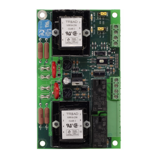
J3, and J4. J1 and J2 provide for voltage monitoring of utility. J3 and J4 provide for voltage monitoring of the generator. Located along the top of the RTC-50 are connectors J6, J7, and J8. J6 provides connections for the control input and the transfer switch control outputs. -
Page 5: Output Connections
This will constitute one maintenance cycle. The RTC-50 will keep track of the number of hours that the gener- ator has run for up to 1000 hours. At this point, the counter will roll over and start again. The information is stored in non-volatile memory so that the value is retained when there is a loss of power. -
Page 6: Section 3: Operation
3.2 Operating Voltage and Measurements The RTC-50 controller operates on an input voltage of 240 Vac with selectable frequency settings of 50 or 60 Hz. The RTC-50 controller operates directly from the line sensing inputs of the Utility and Generator power sources. -
Page 7: Section 4: Programming
Emergency setting of either 20 seconds or 50 seconds. Figure 2. RTC-50 Programming Jumpers. Table 2 is a summary of the Fixed and Jumper-selectable settings that are available in the RTC-50. Table 2. Fixed and Jumper-Selectable Settings DESCRIPTION... -
Page 8: Section 5: Maintenance, Troubleshooting, And Replacement
This manual is written with the assumption that only ATS trouble- shooting will be performed. If the cause of malfunction is traced to an RTC-50, the unit should be replaced with a new unit. The malfunctioning unit should then be returned to Eaton Electrical for factory repairs. -
Page 9: Appendix A: Operational Flowchart
Instruction Manual for the Eaton RTC-50 Automatic Transfer Switch Controller APPENDIX A: OPERATIONAL FLOWCHART Utility is available ATS connects to Utility (Utility Close Output closes) Utility is powering the load Is Utility available? Is Generator available? TDNE timer times out... - Page 10 Instructional Booklet Page 10 Effective: June 2007 Instruction Manual for the Eaton RTC-50 Automatic Transfer Switch Controller Notes For more information visit: www.eaton.com IB00405004E-70-8664...
- Page 11 Instructional Booklet Effective: June 2007 Page 11 Instruction Manual for the Eaton RTC-50 Automatic Transfer Switch Controller Notes: IB00405004E-70-8664 For more information visit: www.eaton.com...
- Page 12 Electrical Group 1000 Cherrington Parkway Moon Township, PA 15108 United States 877-ETN CARE (877-386-2273) www.Eaton.com Instruction Manual for the Eaton RTC-50 Automatic Transfer Switch Controller © 2007 Eaton Corporation All Rights Reserved Printed in USA Publication No. IB00405004E-70-8664/ TBG00148 June 2007...
- Page 13 Manual de instrucciones para el con- trolador RTC-50 del interruptor de transferencia automática Eaton Folleto instructivo Nueva información Descripción 1. Introducción ....... 2 2.
-
Page 14: Información General
ATS. 1.3 Perspectiva general del producto El controlador RTC-50 es un controlador de ATS integral, de funci- ones múltiples, basado en un microprocesador. Diseñado para cumplir con las necesidades de los mercados en el mundo entero, el controlador RTC-50: •... - Page 15 IB00405004E-70-8664 1.5 Funciones/Características La función principal del controlador RTC-50 es monitorizar con precisión las fuentes de alimentación del servicio y del generador, y proporcionar la información necesaria para operar el ATS de manera apropiada y oportuna. Además, el controlador RTC-50 pro- porciona la información del estado a través de indicadores en el...
-
Page 16: Sección 2: Descripción Del Equipo
Figura 1. Conectores y puentes de programación. 2.4 Conectores de entrada/salida Localizados a lo largo de la parte inferior del RTC-50 están los conectores J1, J2, J3 y J4. J1 y J2 proporcionan la monitoriza- ción del voltaje del servicio. J3 y J4 proporcionan la monitoriza- ción del voltaje del generador. -
Page 17: Conexiones De Salida
Eaton 2.5 Entrada para "ir al generador" El RTC-50 tiene una señal de entrada de control que iniciará una transferencia del servicio al generador. La entrada requiere un cierre de un contacto externo para la entrada para ir al generador (J6, bornes 1 y 2). - Page 18 3.2 Voltaje operativo y mediciones El controlador RTC-50 opera con un voltaje de entrada de 240 V CA con selecciones de frecuencia de 50 ó 60 Hz. El controlador RTC-50 opera directamente de las entradas senso- ras de la línea de las fuentes de alimentación del servicio y del...
- Page 19 20 segundos o de 50 segundos. Figura 2. Puentes para programación del RTC-50. La tabla 2 es un resumen de las selecciones fijas y seleccionables con puente que se encuentran disponibles en el RTC-50. Tabla 2. Selecciones fijas y seleccionables con puente DESCRIPCIÓN...
-
Page 20: Mantenimiento Y Cuidado
SECCIÓN 5: MANTENIMIENTO, RESOLUCIÓN DE PROBLEMAS Y REEMPLAZO 5.1 Mantenimiento y cuidado El RTC-50 está diseñado para ser una unidad independiente y libre de mantenimiento. El tablero de circuitos impreso está cubierto en fábrica por un revestimiento protector conforme a la superficie. El RTC-50 debe ser mantenido solamente por personal entrenado en la fábrica para su servicio. - Page 21 Manual de instrucciones para el controlador RTC-50 del interruptor de transferencia automática Eaton APÉNDICE A: DIAGRAMA OPERATIVO El servicio se encuentra disponible. El ATS se conecta al servicio. (La salida del servicio cerrado se cierra.) El servicio está alimentando a la carga.
- Page 22 Folleto instructivo Página 10 Efectivo: Junio 2007 Manual de instrucciones para el controlador RTC-50 del interruptor de transferencia automática Eaton Notas: Para mayor información, visite: www.eaton.com IB00405004E-70-8664...
- Page 23 Folleto instructivo Efectivo: Junio 2007 Página 11 Manual de instrucciones para el controlador RTC-50 del interruptor de transferencia automática Eaton Notas: IB00405004E-70-8664 Para mayor información, visite: www.eaton.com...
- Page 24 1000 Cherrington Parkway Moon Township, PA 15108 Estados Unidos 877-ETN CARE (877-386-2273) www.Eaton.com Manual de instrucciones para el controlador RTC-50 del interruptor de transferencia automática Eaton © 2007 Eaton Corporation Todos los derechos reservados Impreso en los Estados Unidos Publicación nº IB00405004E-70-8664/ TBG00148...
- Page 25 Mode d'emploi de la commande RTC- 50 pour commutateur de transfert automatique 50 Eaton Livret d'instructions Nouveau document Sommaire 1. Introduction ....... 2 2.
-
Page 26: Introduction
La commande RTC-50 est une commande complète d'ATS, à microprocesseurs et à fonctions multiples. Conçue pour satisfaire les besoins des marchés du monde entier, la commande RTC-50 : • est une pièce homologuée UL; • est conforme aux normes 1008 UL et 22.2-178 CSA;... - Page 27 Mode d'emploi de la commande RTC-50 pour commutateur de transfert automatique 50 Eaton La commande RTC-50 fournit un degré inégalé de souplesse de programmation afin de répondre aux besoins quel que soit le cir- cuit. Elle fonctionne sur courant alternatif de 240 volts, uniphasé...
-
Page 28: Description Du Matériel
RTC-50. 2.4 Connecteurs d'entrée et de sortie Placés le long du bas de la commande RTC-50 se trouvent les con- necteurs J1, J2, J3 et J4. Les J1 et J2 fournissent le contrôle de la tension du courant secteur, les J3 et J4 celui de la tension de la génératrice. - Page 29 Lorsque cette entrée (J6, broches 1 et 2) est "branchée", la com- mande RTC-50 enclenche le transfert entre le courant secteur et la génératrice. La génératrice doit être démarrée manuellement ou le courant doit être coupé dans les fils de détection du courant sect- eur afin d'enclencher un démarrage de moteur.
-
Page 30: Résumé Des Caractéristiques
3.2 Tension d'utilisation et mesures La commande RTC-50 fonctionne sur une tension de 240 volts de c.a., à une fréquence de 50 ou 60 Hz, à sélectionner. La commande RTC-50 fonctionne directement à partir des entrées de détection de courant des sources de courant secteur et de... -
Page 31: Programmation
à secours de 20 secondes ou de 50 sec- ondes. Figure 2. Cavaliers de programmation de la commande RTC-50. Le tableau 2 est un résumé des réglages fixes et à choisir avec cavaliers dans la commande RTC-50. Tableau 2. Réglages fixes et à choisir avec cavaliers DESCRIPTION Temporisation de normal à... -
Page 32: Entretien Et Dépannage
La commande RTC-50 est conçue pour être un dispositif auto- nome et ne nécessitant aucun entretien. La carte de circuits imprimés a été enduite en usine. La commande RTC-50 ne doit être réparée que par du personnel formé en usine. -
Page 33: Annexe A : Ordinogramme De Fonctionnement
Mode d'emploi de la commande RTC-50 pour commutateur de transfert automatique 50 Eaton ANNEXE A : ORDINOGRAMME DE FONCTIONNEMENT Courant secteur disponible Le commutateur ATS se relie au courant secteur (la sortie de fermeture du courant secteur se ferme) Le courant secteur alimente la charge... - Page 34 Livret d'instructions Page 10 En vigueur dès juin 2007 Mode d'emploi de la commande RTC-50 pour commutateur de transfert automatique 50 Eaton Remarques: Pour de plus amples renseignements, visitez: www.eaton.com IB00405004E-70-8664...
- Page 35 Livret d'instructions En vigueur dès juin 2007 Page 11 Mode d'emploi de la commande RTC-50 pour commutateur de transfert automatique 50 Eaton Remarques: IB00405004E-70-8664 Pour de plus amples renseignements, visitez: www.eaton.com...
- Page 36 Electrical Group 1000 Cherrington Parkway Moon Township, PA 15108 États-Unis 877-ETN CARE (877-386-2273) www.Eaton.com Mode d'emploi de la commande RTC-50 pour commutateur de transfert automatique 50 Eaton © 2007 Eaton Corporation Tous droits réservés Imprimé aux États-Unis Document IB00405004E-70-8664/ TBG00148...
Need help?
Do you have a question about the RTC-50 and is the answer not in the manual?
Questions and answers