Table of Contents
Advertisement
ENGLISH
RF9601 - Z-WAVE PLUS WIRELESS SWITCH
RF9617 - Z-WAVE PLUS ACCESSORY SWITCH - For multi-locations
WARNINGS AND CAUTIONS:
• Turn circuit breaker to OFF position or remove fuse(s) and test that power is OFF before installation process.
• Never wire any electrical device with power turned ON. Wiring switch HOT may cause permanent damage to switch and void
warranty.
• If you are not sure about any part of these instructions, please contact a licensed electrician.
IMPORTANT: Z-Wave Wireless Switch will not work or will become damaged if wired incorrectly and warranty will be voided. Refer to wiring
instructions provided .
• Use only with 120V/AC 60 Hz.
• Do not exceed maximum rating of switch as indicated on the device.
• Must be installed and used in accordance with all national and local electrical codes.
• If a bare copper or green ground connection is not available in the wallbox, contact a licensed electrician for installation.
• Use only #14 or #12 copper wire rated for at least 75º C with these devices. DO NOT USE WITH ALUMINUM WIRE.
NOTES:
•.The Z-Wave Wireless Switch is wired directly to the light fixture.
• For Multi-location applications (3-Way or 4-Way) the Z-Wave Wireless Accessory Switch (RF9617) or a regular 3-way toggle switch could
be used along with one Z-Wave Master Switch
• The Z-Wave Wireless Accessory Switch communicates via RF signals to control the light from more than one location.
• For multi-location control use Z-Wave Wireless switch directly wired to the light along with Z-Wave Wireless Accessory Switch (RF9617).
The Z-Wave Accessory does not require direct connection to the light (use Association function).
Electrical Ratings:
Current Capacity: 15Amps (RF9601 only)
Horsepower: 1/2HP (RF9601 only)
Voltage: 120Vac
Frequency: 60Hz
Z-WAVE DEVICE NETWORK INSTRUCTIONS:
This product may be added to a new or existing Z-Wave network. An Eaton Wiring Devices Z-Wave device has a blue LED,
which will blink when the device is not included in a Z-Wave network. The LED stops blinking when the device is in a network.
This product works with other Z-Wave Plus products from different vendors and product categories as part of the same network.
This product is a listening node and it will act as a repeater in the Z-Wave network. It will perform the repeater function with
Z-Wave products from Eaton and from other Z-Wave vendors.
This secure Z-Wave Plus device will only associate with other secure devices based on the Z-Wave controller it's being used with.
Please refer to instructions provided with the controller for more details.
Adding Z-Wave Wireless switch to a Z-Wave Network:
1. To include this device in a Z-Wave network, select the command on your Z Wave controller for inclusion (Install, Add Device,
Add Node, Include Device, etc.). Then press the device ON/OFF switch one time to include it in the network.
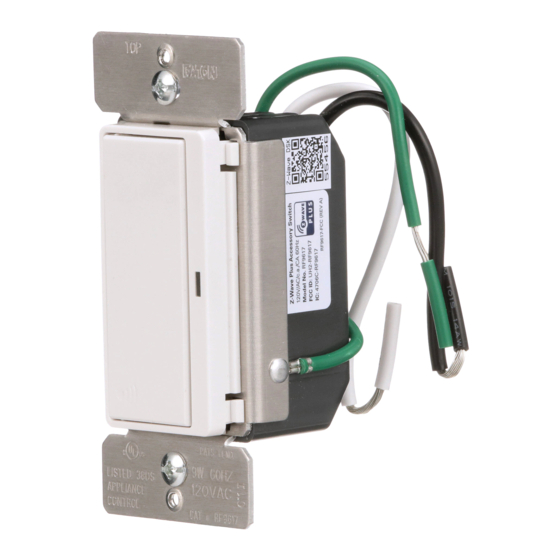
2. Based on the controller, the controller may ask you to scan the QR code or manually enter 5 digit code under the QR code
to install the device as a secured device. You may find this QR code on the device or included in device packaging (Figure 1).
3. After the Device is added to the network, the blue indicator LED will stop blinking. This indicates the device is installed in the Z-Wave
network.
Removing Z-Wave Wireless switch from a Z-Wave Network:
1. To exclude this device from a Z-Wave network, select the setting on your Z-Wave controller for exclusion
(Uninstall, Remove Device, Remove Node, Exclude Device, etc.).
2. Once your controller is in exclusion mode, press the device ON/OFF switch one time to exclude it from the network. The LED will start
blinking.
For a Quick start Guide on how to install this device with Eaton's Home Automation Hub & other compatible Z-Wave Certified Controllers,
please scan the QR code (Figure 2).
Operating Instructions:
• Press ON/OFF button once to turn lights/load ON.
• Press ON/OFF button again to turn lights/load OFF.
• Delayed OFF: When overhead lights are ON, press and hold ON/OFF button for 2 seconds until the blue LED blinks. After the preset delay,
the lights will turn OFF (Default present delay is 10 seconds; you can configure this through a compatible Z-Wave controller for up to
2 minutes).
• Indicator Light stays ON at dim level when the switch is OFF to act as pilot light (this can be turned OFF using following instructions)
Changing LED Indicator brightness: (RF9601 & RF9617):
• This feature allows the change of the brightness of the blue LED indicators on the device.
• There are 5 levels (including fully OFF and full brightness) to change the LED indicator brightness level
either while the device is ON or OFF state.
Changing the LED indicator brightness when the device is an ON state:
1. Turn the overhead light ON.
2. Press and hold the ON/OFF button for 15 seconds till the LED indicator flashes for the second time.
3. Release the ON/OFF button.
4. Single tap the ON/OFF button to change the LED indicator level (it will cycle between the five levels.
5. Once the brightness level is selected, double tap on the ON/OFF button and this value will be saved
Changing the LED indicator brightness when the device is an OFF state:
1. Turn the overhead light OFF.
2. Press and hold the ON/OFF button for 15 seconds till the LED indicator flashes for the first time.
3. Release the ON/OFF button.
4. Single tap the ON/OFF button to change the LED indicator level (it will cycle between the five levels.
5. Once the brightness level is selected, double tap on the ON/OFF button and this value will be saved
Local Reset (RF9601 & RF9617)(Please use this procedure only when the network primary controller is missing or otherwise inoperable)
The device could be reset locally. This will cause the device to be excluded from its network and restore to factory default.
Before leaving the network the switch will send a notification to the controller indicating its departure from the Z-Wave network.
1. Turn the device ON.
2. Press and hold ON/OFF button for 20 second till the LED flashes for the third time.
3. Release the ON/OFF button.
4. LED will start flashing rapidly. Once the LED starts blinking slowly, that indicates the device is not part of the network.
ON/OFF Button
Switch Identification
Master Control
Configuration parameters:
RF9601 & RF9617
Parameter
Description
1
Delayed OFF Time
2
Panic ON Time
3
Panic OFF Time
4
Not Used
5
Power Up State
6
Panic Mode Enable
7-12
Not Used
13
BLUE LED Brightness Level while the
Switch is ON
.
14
BLUE LED Brightness Level while the
Switch is OFF
.
Single Location (RF9601)
Hot 120V
Black
ON/OFF LED
Ground
Green
Indicator
White
Neutral
Neutral
3-Way with a master switch (RF9601) and an Accessory switch (RF9617) through Z-Wave Association
Hot 120V
Black
Green
Ground
Accessory
White
Neutral
Master Switch RF9601
Neutral
3-Way with a master switch (RF9601), Accessory switch (RF9617) through Z-Wave Association and toggle switch
Figure 1
(For Reference Only)
Hot 120V
Black
Ground
Green
Value
White
0 to 127 secs
Neutral
0 to 127 secs
0 to 127 secs
Master Switch RF9601
Neutral
N/A
1 = OFF 2 = ON
3 = Last State
0 = OFF
1 = ON
N/A
0-4
0-4
Quick Start Guide
Figure 2
3-Way with an RF master switch (RF9601) and a toggle switch
Red
Hot 120V
Black
Ground
Green
Light Fixture
Blue
White
3-Way
Neutral
Neutral
Red
Hot 120V
Black
Light Fixture
Blue
White
3-Way
Neutral
Accessory Switch RF9617
Red
Hot 120V
Black
Light Fixture
Blue
3-Way
White
Neutral or Hot
or Ground
Neutral
Accessory Switch RF9617
Red
Light Fixture
Blue
Neutral or Hot
3-Way
or Ground
Green
Ground
Green
Ground
www.eaton.com
www.eaton.com/wiringdevices
EIS-0243-E (REV.B)
Advertisement
Table of Contents

Related Manuals for Eaton RF9601


Summary of Contents for Eaton RF9601
- Page 1 Hot 120V Black This product may be added to a new or existing Z-Wave network. An Eaton Wiring Devices Z-Wave device has a blue LED, Hot 120V which will blink when the device is not included in a Z-Wave network. The LED stops blinking when the device is in a network.
- Page 2 To obtain warranty service for any properly installed Eaton switch that proves defective in normal use send the defective switch prepaid and insured to Quality Control Dept., Eaton Wiring Devices, 203 Cooper Circle, Peachtree City, GA 30269;...
Need help?
Do you have a question about the RF9601 and is the answer not in the manual?
Questions and answers