Table of Contents
Advertisement
Quick Links
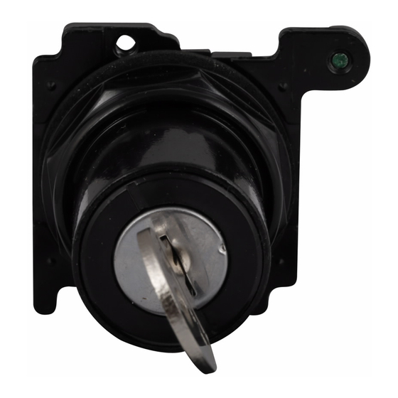
Instructions and Operation P20442
Heavy Duty Oiltight Selector Switch
Units - 10250T/91000T or E34
Underwriters Laboratories Listed
For use on a flat surface of Type
®
1, 2, 3, 3R, 4, 4X, 12 and 13
enclosures. IP 65
1. Select the desired schematic circuit function from the chart below and
note in your cam column the type of contacts, N.O. or N.C., the "A" and
"B" circuit locations, and any series or parallel jumper connections the may
be required.
2. Choose contact blocks that have the required schematic circuits and
assemble in any convenient sequence that fulfills the "A" and "B" circuit
location requirements.
NOTE: Single circuit contact blocks, if used, must be last in the stack and
positioned so that the plunger motion is transmitted through.
3. Make the indicated series or parallel jumper connections.
(10250T/91000TA70,TA71).
4. If this operator was received without an operating cap, assemble the
separately purchased cap, assemble the separately purchased cap and secure
with the screws provided.
NOTES: Single, double and 2NO-2NC contact blocks are available. Six contacts
can be stacked in each of the two circuit locations making a maximum of
twelve circuits possible.
For additional selector switch explanation ask for manual NU-118.
The selector switch operator in this package may not be complete. A knob,
lever, coin slot or knob type lens operating cap is required wich may be
merchandised and packaged separately.
WIRING INSTRUCTIONS
The illustration shows the circuit conditions that result for each position of
the selector switch.
ASSEMBLY INSTRUCTIONS
US 60/75°C COPPER CONDUCTORS ONLY
.136 (3.5 mm) dia. hole or
.180 (4.6 mm) rectangular
.60 (15.2 mm)
notch
VERTICAL MOUNTING
1.20 (30.5 mm)
HORIZONTAL MOUNTING
Effective February 2018
Supersedes July 2011
The two sections of the operating cam of this selector switch work
independently, so it is important that the contact blocks be oriented with
their plungers in the correct "A" and "B" circuit locations. The sketch below
identifies these positions with respect to the locatin nib or marked top.
LIGHT MODULE OF CONTACT BLOCK
Grounding nibs
Locating nib
Operating cab
Knob, Lever, Coin, Slot, Key or Knob
Type Lense
Sketch shows VERTICAL MOUNTING. For HORIZONTAL MOUNTING
loosen the set screw and assemble so that the locating nib is at the left.
ILLUMINATED GASKET INSTRUCTIONS This operator was shipped with
the gasket oriented for VERTICAL MOUNTING using lever lens and the
new type knob lens.
For HORIZONTAL MOUNTING (or VERTICAL MOUNTING using the old
type knob) carefully peel the lens gasket, rotate it 90°, and press onto the
operator. (Lens screws will now thread into alternate holes).
LAMB REMOVAL TOOL For Trans. Type Cat. No. 10250TA74 for Full Voltage
Type E30KV1.
For Replacement Gasket Order PT #32-803
L
R
COM
1A
X
O
O
X
1B
10250T/91000T20
10250T/91000T21
SERIES OR E34
SERIES OR E34
L
C R
COM
X
O O
O
O X
COM
O
X O
10250T/91000T22
10250T/91000T46
SERIES OR E34
SERIES OR E34
1. Drill mounting hole for vertical or horizontal mounting per one of the figures
above.
2. ensure sealing gasket is in the place on the operator. Align location nib
of the operator with notch in the panel and insert operator through mount-
ing hole.
3. Place legend plate and mounting nut over operator. Tighten mounting
nut. If applicable assemble buttons to operator. Tighten securely (5 ft-lbs)
(6.8 Nm).
4. Torque terminals to 12 in/lbs (1.4 Nm).
For ease of assembly, we recommend the following tools:
91000T/10250TA95
(for 10250T/91000T octagonal nut, E29 and E30 line)
E22CW
(for 10250T/91000T octagonal nuts, E22, E30 and E34)
5. Torque contact block stacking screws to 5-7 in/lbs (0.57- 0.79 Nm)
or top
Circuit
"A"
Circuit
"B"
Set screw
Retaining Nut
Use 1/16"
To be changed in Coin
Allen Wrench
Slot Assembly
Vertical Mounting
New
Knob
Lever
L
C R
1A
X O O
O O X
1B
Heavy lines indicates
1 2 3 4
costumers connections.
X O O O
Light lines are factory
installed jumpers
O X O O
X=circuit closed
O O X O
O=circuit open
O O O X
1-2-3-4=4 position switch
L=Left
C=Center
R=Right
Advertisement
Table of Contents

Subscribe to Our Youtube Channel
Related Manuals for Eaton 10250T/91000T


Summary of Contents for Eaton 10250T/91000T
- Page 1 4. Torque terminals to 12 in/lbs (1.4 Nm). 1.20 (30.5 mm) For ease of assembly, we recommend the following tools: 91000T/10250TA95 (for 10250T/91000T octagonal nut, E29 and E30 line) E22CW (for 10250T/91000T octagonal nuts, E22, E30 and E34) VERTICAL MOUNTING HORIZONTAL MOUNTING 5.
- Page 2 O O X -Ordinarily, these operators should not be used with overlap and early closing contact O X X blocks (10250T/91000T55, T56, T57 and T58). Contact local EATON sales office on specific application. O X O INSTRUCTIONS FOR THE ASSEMBLY OF THE PADLOCK ATTACHMENT E34TA11, 10250T/91000TA11...
-
Page 3: Assembly Instructions
Heavy Duty Oiltight Selector Switch Instructions and Operation P20442 SWITCH UNITS-10250T/91000T OR E34 Effective February 2018 INSTRUCTIONS FOR THE ASSEMBLY Underwriters Laboratories Listed OF HEAVY DUTY OILTIGHT ROTO-PUSH For use on a flat surface of Type ® 1, 2, 3, 3R, 4, 4X, 12 and 13 UNITS enclosures. - Page 4 Electrical Sector 1111 Superior Avenue Cleveland, OH 44114 United States 877-ETN-CARE (877-386-2273) Eaton.com Eaton is a registered trademark of Eaton © 2011 Eaton Corporation Corporation. All Rights Reserved All other trademarks are property of their Publication No. P20442 / 004 respective owners.
Need help?
Do you have a question about the 10250T/91000T and is the answer not in the manual?
Questions and answers