
Subscribe to Our Youtube Channel
Related Manuals for Eaton Cutler-Hammer RTHMFDA20100WSU


Summary of Contents for Eaton Cutler-Hammer RTHMFDA20100WSU
- Page 1 Cutler-Hammer I.B. ATS-RM05 Instructions for Cutler-Hammer Residential Automatic Transfer Switch Effective 6/01, Supersedes ATS-RMO4 dated June 2000...
- Page 3 I.B. ATS-RM05 Page iii TRANSFER SWITCH EQUIPMENT COVERED BY THIS INSTRUCTION BOOK IS DESIGNED AND TEST- WARNING ED TO OPERATE WITHIN ITS NAMEPLATE RAT- INGS. OPERATION OUTSIDE OF THESE RATINGS MAY CAUSE THE EQUIPMENT TO FAIL RESULTING READ AND UNDERSTAND THE INSTRUCTIONS IN DEATH, SERIOUS BODILY INJURY AND/OR CONTAINED HEREINAFTER BEFORE ATTEMPTING PROPERTY DAMAGE.
-
Page 4: Table Of Contents
I.B. ATS-RM05 Page iv TABLE OF CONTENTS Page SECTION 1: INTRODUCTION Preliminary Comments and Safety Precautions....................1 1.1.1 Warranty and Liability Information ......................1 1.1.2 Safety Precautions ..........................1 General Information.............................1 1.2.1 Design Configuration ..........................2 Transfer Switch Catalog Number Identification ....................2 Environmental Conditions ...........................3 SECTION 2: RECEIVING, HANDLING AND STORAGE Receiving................................4 Handling ................................4... - Page 5 I.B. ATS-RM05 Page v Page SECTION 6: ADJUSTMENTS Plant Exerciser PE Timer ..........................16 6.1.1 Timer Programming..........................16 6.1.2 Provisions for Extended PE Memory....................16 SECTION 7: MAINTENANCE Introduction................................17 Procedures ................................17 Maintenance Log ..............................20 Effective 6/01...
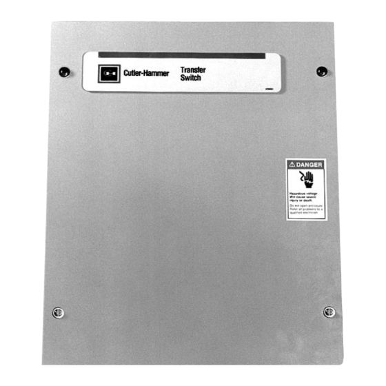
- Page 6 I.B. ATS-RM05 Page vi LIST OF FIGURES Figure Title Page Typical Load Transfer Switch (circuit breaker type) Schematic..............1 Typical Residential Automatic Transfer Switch..................3 Dimensions and Plan View of Residential Automatic Transfer Switch (30 -100A) ........7 Dimensions and Plan View of Residential Automatic Transfer Switch (150 -200A) ........7 Cover Removal ............................8 Deadfront Removal ...........................9 Cable Connections ............................9...
-
Page 7: Section 1: Introduction
I.B. ATS-RM05 Page 1 SECTION 1: INTRODUCTION CAUTION 1.1 PRELIMINARY COMMENTS AND SAFETY PRECAUTIONS READ AND UNDERSTAND THE MATERIAL PRE- This technical document is intended to cover most SENTED IN THIS DOCUMENT BEFORE ATTEMPTING aspects associated with the installation, application, INSTALLATION, OPERATION OR APPLICATION OF operation and maintenance of the Residential Automatic THE EQUIPMENT. -
Page 8: Design Configuration
I.B. ATS-RM05 Page 2 the normal power source, again depending upon the 1.2.1 DESIGN CONFIGURATION type of transfer equipment being used (Figure 1-1). The Cutler-Hammer transfer switch is a rugged, com- In automatic transfer switch equipment, the switch’s pact design that utilizes molded case switches to trans- intelligence system initiates the transfer when normal fer essential loads from one power source to another power fails or falls below a preset voltage. -
Page 9: Environmental Conditions
I.B. ATS-RM05 Page 3 represented by the control panel is microprocessor logic. The frame is for 100 amp service, and the switch is a 2-pole, fixed mount molded case switch. The contin- uous current rating of this equipment is 100 amperes and applicable at 240 VAC, 60Hz. -
Page 10: Section 2: Receiving, Handling And Storage
I.B. ATS-RM05 Page 4 SECTION 2: RECEIVING, HANDLING, AND 2.2 HANDLING STORAGE As previously mentioned, transfer switch equipment is packaged in its own box. Protect the equipment from 2.1 RECEIVING impact at all times and do not double stack. Once the equipment is in the installation location and ready to be Every effort is made to ensure that the transfer switch installed, packaging material can be removed. -
Page 11: Section 3: Equipment Description
I.B. ATS-RM05 Page 5 Failsafe SECTION 3: EQUIPMENT DESCRIPTION Failsafe refers to the condition whereby the transfer switch is connected to the Emergency Source. In the 3.1 INTRODUCTION event that the Emergency Source fails and the Normal Source is available, an immediate retransfer to the Nor- The Cutler-Hammer Residential Automatic Transfer mal Source shall occur. - Page 12 I.B. ATS-RM05 Page 6 b. In standby systems, in accordance with article 702 of the National Electrical Code and/or c. In legally required standby systems in accordance with article 701 of the National Electrical Code. Cutler-Hammer automatic transfer switches are avail- able to meet NFPA110 for emergency and standby power systems, and NFPA99 for health care facilities when ordered with the appropriate options.
-
Page 13: Section 4: Installation And Wiring
I.B. ATS-RM05 Page 7 SECTION 4: INSTALLATION AND WIRING 4.2 MOUNTING LOCATION Choose a location that offers a flat, rigid mounting sur- 4.1 GENERAL face capable of supporting the weight of the enclosed transfer switch equipment (Figure 4-1, 30-100A or Transfer switches are factory wired and tested. -
Page 14: Mounting Procedure
I.B. ATS-RM05 Page 8 Carefully remove all packing material from the transfer NOTICE switch at the mounting location. Do not discard the Top Cardboard Pad. It is used as a template for locating the mounting holes. Even though an equipment inspection was made when the equipment was received, make For control wiring (Generator start wiring), these another careful inspection of the enclosure and the... -
Page 15: Power Cable Connections
I.B. ATS-RM05 Page 9 E1 E2 N1 N2 T1 T2 Ground Screw Neutral Figure 4-4 Deadfront Removal Figure 4-5 Cable Connections 4.4 POWER CABLE CONNECTION CAUTION WARNING TO HELP PREVENT COMPONENT DAMAGE OR FUTURE MALFUNCTIONS, USE EXTREME CARE TO POWER CONDUCTORS MAY HAVE VOLTAGE PRE- KEEP CONTAMINANTS OUT OF THE TRANSFER SENT THAT CAN CAUSE SEVERE PERSONAL SWITCH EQUIPMENT WHEN MAKING POWER... -
Page 16: Wiring
I.B. ATS-RM05 Page 10 generator. A line breaker is required between the emer- gency source (generator) and the transfer switch (Figure CAUTION 4-8). When normal power returns, the ATS will switch all power back to the utility and shut down the generator. IMPROPER POWER CABLE CONNECTIONS CAN In addition, another typical installation for household CAUSE EXCESSIVE HEAT AND SUBSEQUENT... -
Page 17: Typical Installation Of A Residential Or Light Duty Automatic Transfer Switch
I.B. ATS-RM05 Page 11 Power Cables Control Wiring Figure 4-6 Typical installation of a residential or light duty automatic transfer switch. The switch (1) and generator (2) are connected to the power supply. The automatic transfer switch is located between the emergency distribution (3) and the utility panel (4). -
Page 18: Diagram Of Typical Installation (Critical Loads Only)
I.B. ATS-RM05 Page 12 (Typically included in Genset) Figure 4-8 Diagram of Typical Installation (Critical Loads Only) Transfer Switch Emergency Source Circuit Breaker Circuit Breaker Watt-Hour Meter Main Breaker Panel Household Loads Figure 4-9 Diagram of Typical Installation (All Household Loads) Effective 6/01... -
Page 19: Terminal Block Wire Installation And Removal
I.B. ATS-RM05 Page 13 4.9 TERMINAL BLOCK WIRE INSTALLATION AND REMOVAL Proceed with the following steps and associated pic- tures to install or remove terminal block wiring. Tool Hole Wire Hole Step 3: Once the screwdriver is in place, obtain a stripped wire (strip about 1/4 of an inch) and insert it into the larger circular wire hole. - Page 20 I.B. ATS-RM05 Page 14 Step 9: After the shorting strap and lock are in place, the plug can be attached by sliding the single row of holes at the bottom of the piece overtop the metal rods of the terminal block. Match the rounded edge of the plug with the rounded edge of the terminal block and Shorting Strap Hole gently push the pieces together.
-
Page 21: Section 5: Functional Testing
I.B. ATS-RM05 Page 15 5.3 OPERATIONAL CHECKS SECTION 5: FUNCTIONAL TESTING Step 1: Open the upstream normal breaker originally closed in Step 2 of Section 5.2. WARNING NOTICE YOU ARE READY TO ENERGIZE THE EQUIPMENT. VOLTAGES WITHIN THE ENCLOSURE ARE CAPA- BLE OF CAUSING SEVERE PERSONAL INJURY OR This will simulate an interruption of the normal DEATH. -
Page 22: Section 6: Adjustments
I.B. ATS-RM05 Page 16 SECTION 6: ADJUSTMENTS 6.1 PLANT EXERCISER PE TIMER Option 23, described in Section 3.2, is a plant exerciser. The plant exerciser is a once every 7-day timer switch used to exercise the engine driven generator. 6.1.1 TIMER PROGRAMMING Depress the PE Switch located on the end of the printed circuit board for 2 seconds and release. -
Page 23: Section 7: Maintenance
I.B. ATS-RM05 Page 17 SECTION 7: MAINTENANCE nance checks should be made on a regularly scheduled basis. Since equipment maintenance will consist mainly of keeping the equipment clean, the frequency of main- 7.1 INTRODUCTION tenance will depend, to a large extent, on the cleanli- ness of the surroundings. -
Page 24: Wiring Diagram For Residential Automatic Transfer Switch
I.B. ATS-RM05 Page 18 Emergency Normal P2-1 P3-1 P3-3 P2-3 P1-3 P1-1 P1-2 Motor P5-1 P1-4 Normal Emergency P4-2 P4-1 NO NC NO NC P5-4 P5-3 Engine Start OPTIONAL Figure 7-1 Wiring Diagram for Residential Automatic Transfer Switch Effective 6/01... - Page 25 I.B. ATS-RM05 Page 19 Table 7.1 Periodic Maintenance Procedures Step Action a. Make transfer switch equipment safe for Disconnect line power from equipment being serviced by inspection and/or maintenance. opening next highest disconnect device. Make certain that any accessory control power is switched off. b.
-
Page 26: Maintenance Log
I.B. ATS-RM05 Page 20 7.3 MAINTENANCE LOG Date Action Ex: 1/1/XX Changed Battery Effective 6/01... - Page 28 I.B. ATS-RM05 This instruction booklet is published solely for informa- tion purposes and should not be considered all inclu- sive. If further information is required, you should con- sult Cutler-Hammer. Sale of product shown in this literature is subject to terms and conditions outlined in appropriate Cutler- Hammer selling policies or other contractual agreement between the parties.
Need help?
Do you have a question about the Cutler-Hammer RTHMFDA20100WSU and is the answer not in the manual?
Questions and answers