Table of Contents
Advertisement
Quick Links
Advertisement
Table of Contents

Related Manuals for Eaton ATS 16


Summary of Contents for Eaton ATS 16
- Page 1 _________ l � -' -------- - - Статические переключатели Eaton ATS 16 - руководство по эксплуатации. Юниджет Постоянные ссылки на страницы: https://www.uni-jet.com/catalog/staticheskie-avr/eaton-ats-16.html https://www.uni-jet.com/catalog/staticheskie-avr/eaton-ats-16-netpack.html...
- Page 2 EATS16 EATS16N Installation and user manual Copyright © 2015 EATON All rights reserved. Service and support: Call your local service representative EATS16_EN...
- Page 3 ATS. The EATON ATS models that are covered in this manual are intended for installation in an environment within 0°C to 40°C (32°F to 104°F) and free of conductive contaminant.
-
Page 4: Table Of Contents
4. Power cables connection ............... 12 Installation diagram ...................... 12 Input/Output connection EATS16 - EATS16N............... 12 5. Communication ................13 Communication ports: EATS16N ................. 13 Eaton Intelligent Power Software suite ............... 14 6. Maintenance ................... 15 Troubleshooting ......................15 7. Specifications .................. 16 Page 3... -
Page 5: Introduction
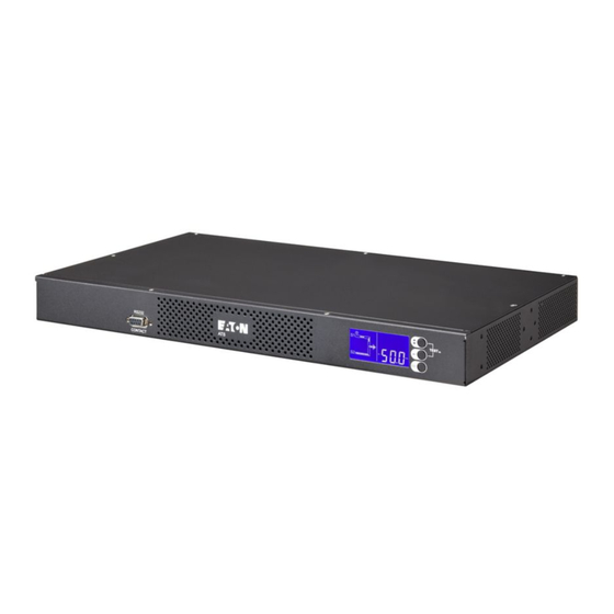
1. Introduction The EATON Automatic T ransfer Switch (ATS) is a high availability switch designed for providing redundant power for sensitive equipment. It is powered by two independent power sources and automatically makes a rapid switch from one source to the other when the power supply used to power its connected load fails. This ATS is designed to be efficient and reliable. Users can know EATON ATS’s power flow, status, parameters from the LCD interface. Besides, the EATS16N unit has a network interface for users to read and write parameters. T he network interface can be implemented via the Ethernet protocol through an RJ45 connector. 2. Presentation Weights and dimensions Rack installation Description... -
Page 6: Lcd Description
2. Presentation LCD description Power flow ATS Settings Measures/Infos Events 2.4.1 Power flow S1 is defined as the priority source (true by default) S2 is defined as the priority source (can be set) S1 not powered S2 not powered S1 powering the load S2 powering the load S1 powered but not powering the load S2 powered but not powering the load Transfer from S1 to S2 Transfer from S2 to S1 Transfer from S1 to S2 for Test Transfer from S2 to S1 for Test Page 5... -
Page 7: Measures
2. Presentation 2.4.2 Measures Output current (default display) Output voltage Input voltage : S1 (default display only when S1 voltage is out of tolerance) Input frequency: S1 (default display only when S1 frequency is out of tolerance) Input voltage : S2 (default display only when S2 voltage is out of tolerance) Input frequency: S2 (default display only when S2 frequency is out of tolerance) - Page 8 2. Presentation Press Enter to reach settings menu OUTPUT ALARM To cancel the changes To select value SENSITIVITY PRIORITY SOURCE TRANSFER Page 7 EATS16_EN...
-
Page 9: Warning
2. Presentation Warning For Fault, refer to troubleshooting section 6.1. Event Example of displays Rootcause Overload Load is over nominal rating Remove some of the equipment from the ATS. T he ATS continues to operate, but may shutdown if the load increases. The alarm resets when the condition becomes inactive. Unsynchronized sources One source N and L are reversed S1 ansd S2 are fed by different phase (L1/L2/L3) S1 and S2 frequency are different Source 1 or Source 2 power loss One of the source is missing, The ATS power on the load with the source that is present. -
Page 10: Installation For Ats
3. Installation for ATS Checking the accessory kit - EATS16 - EATS16N • Verify that the following additional items are included with the ATS: EATS16 User manual Quick start guide Safety manual printed 2 x Input cables: C19-C20 2 x Input cable lockers Plastic strips for output locking RS232 cable Accessories for rack installation EATS16N User manual Quick start guide Safety manual printed 2 x Input cables: C19-C20 2 x Input cable lockers Plastic strips for output locking RS232 cable DB9/RJ45 serial cable for NMC card Accessories for rack installation Page 9 EATS16_EN... -
Page 11: Storage
3. Installation for ATS Storage • Please store the ATS in its original package and in a dry place. Keep the storage temperature between -13 to 131°F (-25°C and +55°C). Installation for rack mounting (normal installation) Follow steps 1 to 3 for module mounting on the rails. Accessories for rack installation • 1 x Ear (Left) • 1 x Ear (Right) • 4 x M4 x 6 flat screw for ear • 4 x M6 x 10 cage nut clip for rack4 • 4 x M6 x 12 flat screw for rack • 4 x M6 washer conical plate for rack Installation for rack mounting (2 post installation) Follow steps 1 to 3 for module mounting on the rails. Accessories for rack installation • 1 x Ear (Left) • 1 x Ear (Right) • 4 x M4 x 6 flat screw for ear... -
Page 12: Wall Installation
3. Installation for ATS Wall installation Follow steps 1 to 2 for module mounting on the wall. Instructions 1. E levated Operating Ambient - If installed in a closed or multi-unit rack assembly, the operating ambient temperature of the rack environment may be greater than room ambient. T herefore, consideration should be given to installing the equipment in an environment compatible with the maximum ambient temperature (Tmax) specified by the manufacturer. 2. Reduced Air Flow - Installation of the equipment in a rack should be such that the amount of air flow required for safe operation of the equipment is not compromised. 3. Mechanical Loading - Mounting of the equipment in the rack should be such that a hazardous condition is not achieved due to uneven mechanical loading. -
Page 13: Power Cables Connection
4. Power cables connection Installation diagram Input Output Input UPS 1 Output to the sensitive equiment Input Output Input UPS 2 Input/Output connection EATS16 - EATS16N Inputs connections Ouput connection to equipment from UPSs outputs 1. Connect input power cables to UPSs output and to ATS inputs (S1 is the default priority source). 2. Connect ATS output to the equipment. Page 12 EATS16_EN... -
Page 14: Communication
2. Connect the other end of the communication cable to the RS232 communication port on the ATS. The ATS can now communicate with EATON power management software. • Characteristics of the optocouplers communication port When a signal is activated, the contact is closed between the common (Pin 4) and the pin of the corresponding signal for n.o contact, and vice versa for n.c contact. common Contact characteristics (optocoupler) • Voltage: 48 V DC max • Current: 25 mA max... -
Page 15: Eaton Intelligent Power Software Suite
5. Communication • Connectivity Cards: EATS16N Connectivity cards allow the ATS to communicate in a variety of networking environments and with different types of devices. The Network-MS card has SNMP and HTTP capabilities as well as monitoring through a Web browser interface; connects to Ethernet network. In addition, an Environmental Monitoring Probe can be attached to obtain humidity, temperature, smoke alarm, and security information. ETHERNET Setting/Sensor 100M UPS data Reset Network-MS card Eaton Intelligent Power Software suite Eaton Software suite provides up-to-date graphics of ATS power and system data and power flow. It also gives you a complete record of critical power events, and it notifies you of important ATS or power information. Page 14 EATS16_EN... -
Page 16: Maintenance
6. Maintenance Troubleshooting Operation status Possible cause Action Overload Power requirement exceeds the Remove some of the equipment ATS capacity (greater than 105 % of from the ATS.The ATS continues nominal). to operate, but may shutdown if the load increases.The alarm resets when the condition becomes inactive. Short-circuit fault A short-circuit occurred. Check device connection or integrity. If error persists, note the alarm message and the ATS serial number, and then contact your service representative. -
Page 17: Specifications
7. Specifications Table 1. Model list Model Operating voltage Current rating Operating frequency EATS16 200/208/220/230/240 Vac 1ɸ 16A 50/60 Hz EATS16N Table 2. Weights and dimensions Model Dimensions H x W x D (mm/inch) Weight (kg/lb) 43 x 438 x 250 /1.7 x 17.24 x 9.84 3.32 / 7.31 EATS16 43 x 438 x 250 / 1.7 x 17.24 x 9.84...
Need help?
Do you have a question about the ATS 16 and is the answer not in the manual?
Questions and answers