Chamberlain APT Owner's Manual
Apt logic 3 industrial duty commercial door operator
Hide thumbs
Also See for APT:
- Addendum (4 pages) ,
- Installation manual (108 pages) ,
- User manual (29 pages)
Table of Contents
Advertisement
Quick Links
INDUSTRIAL DUT Y COMMERCIAL DOOR OPERATOR
2 Y E A R W A R R A N T Y
Serial # Box
Installation Date
O W N E R ' S M A N U A L
A P T
L
ogic
This Operator Features
the Enhanced
PAT E N T P E N D I N G
The Maintenance Alert System™ allows the
installer to set an internal Maintenance
Cycle Counter. The Logic 3 operator
incorporates a self-diagnostic feature built
into the (MAS) Maintenance Alert System
LED. An LED on the 3-button station will
signal
when
the
set
number
cycles/months is reached or when the
operator requires immediate service.
Radio Receiver
Built on Board
315MHz
NOT FOR RESIDENTIAL USE
3
of
Advertisement
Table of Contents
Troubleshooting

Related Manuals for Chamberlain APT


Summary of Contents for Chamberlain APT
- Page 1 ogic O W N E R ’ S M A N U A L A P T INDUSTRIAL DUT Y COMMERCIAL DOOR OPERATOR This Operator Features the Enhanced PAT E N T P E N D I N G The Maintenance Alert System™ allows the installer to set an internal Maintenance Cycle Counter.
-
Page 2: Table Of Contents
T A B L E O F C O N T E N T S SPECIFICATIONS PROGRAMMING Carton Inventory ........3 Control Board Pushbuttons . -
Page 3: Carton Inventory
C A R T O N I N V E N T O R Y Before beginning your installation check that all components were provided. DESCRIPTION POWER HEAD ASSEMBLY OWNER'S MANUAL AND CAUTION LABELS HARDWARE BOX (INCLUDES FASTENERS, TRACK SPACERS, DOOR ARM ASSEMBLY, FRONT IDLER AND HEADER MOUNTING BRACKET) AUTO RECONNECT TROLLEY 3-BUTTON CONTROL STATION WITH LED... -
Page 4: Operator Specifications
O P E R A T O R S P E C I F I C A T I O N S MOTOR ELECTRICAL TYPE: ....... .Continuous Duty TRANSFORMER: . -
Page 5: Preparation
WARNING WARNING P R E P A R A T I O N TRACK ASSEMBLY CAUTION WARNING 1. Using the 3/8"-16 x 3/4" bolts and flange hex nuts provided, assemble the operator track by installing and tightening the To prevent possible SERIOUS INJURY or DEATH: track spacer brackets. -
Page 6: Installation
I N S T A L L A T I O N IMPORTANT NOTE: Before your operator is installed, be sure the door has been properly aligned and is working smoothly. The operator may be wall mounted or mounted on a bracket or shelf. If necessary, refer to the preparation on page 5. Refer to the illustrations and instructions below that suit your application. -
Page 7: Hang The Operator
I N S T A L L A T I O N HANG THE OPERATOR WARNING 1. The illustration below shows a typical method of hanging the operator from the ceiling. Each installation may vary, but in all To avoid possible SERIOUS INJURY from a falling operator, cases side braces should be used for additional strength. -
Page 8: Entrapment Protection Accessories
I N S T A L L A T I O N ENTRAPMENT PROTECTION ACCESSORIES WARNING (OPTIONAL) PHOTO EYES & SENSING EDGES To reduce the risk of SEVERE INJURY or DEATH, ALWAYS install reversing sensors when the 3-button control station is Sensing devices provided for door industry type operators with an CAUTION out of sight of door or ANY other control (automatic or manual) -
Page 9: Emergency Disconnect System
A D J U S T M E N T EMERGENCY DISCONNECT SYSTEM WARNING TO DISCONNECT DOOR FROM OPERATOR To prevent possible SERIOUS INJURY or DEATH from a falling The door should be in the fully closed position, if possible. Pull door or arm: CAUTION down on the emergency release handle and raise or lower the... -
Page 10: Brake Adjustment
A D J U S T M E N T BRAKE ADJUSTMENT The solenoid brake is adjusted at the factory and should not need additional adjustment for the life of the brake assembly. Brake Assembly Replace brake assembly when necessary. Refer to the illustration for identification of components for the solenoid type brake system. -
Page 11: Safety Warnings
P O W E R W I R I N G & G R O U N D W I R I N G NING WARNING WARNING To reduce the risk of SEVERE INJURY or DEATH: • ALL electrical connections MUST be made by a qualified individual. -
Page 12: Control Station Wiring & Installation
TIMER DEFEAT DEFEAT If the door moves in the wrong direction and or the limits move PHOTO EYES (LiftMaster Only) EYES in the wrong direction, simply move the motor direction jumper EYES located on the logic board from the factory default setting (STD) -
Page 13: Standard Power & Control Connection Diagrams
S T A N D A R D P O W E R & C O N T R O L C O N N E C T I O N D I A G R A M S OPEN Maintenance Alert LED CLOSE... -
Page 14: Phase Wiring Diagram
L O G I C ( V E R . 3 . 0 ) 1 P H A S E W I R I N G D I A G R A M OPEN Maintenance CLOSE Alert LED (RD) (WH) STOP Open 3-Button... -
Page 15: Control Board
C O N T R O L B O A R D Ø14LGØ657–A Ø14GPØ657–A C3Ø Auxilliary Board Motor Direction Connectors Jumper D3Ø2 P1Ø Single Phase & Three Phase Jumper Programmed Chip POWER TIMER J3ØØ TIMER Maintenance Alert DEFEAT DEFEAT System Button for Programming Maximum Run Timer Button... -
Page 16: Control Board Pushbuttons
P R O G R A M M I N G LOGIC CONTROL PUSHBUTTONS OPEN, CLOSE, STOP SELECTOR DIAL Open, Close and Stop buttons are mounted directly on the logic board. Thus, making it easy to program as well as have door control at the electrical box. -
Page 17: Failsafe Wiring Types
P R O G R A M M I N G FAILSAFE WIRING TYPES B2 Failsafe Same functions as B2. Self Monitoring safety device must be installed to operate door for each of TYPE the following failsafe wiring types. See Self Momentary contact to open, close, and stop with Monitoring Safety Device Options. -
Page 18: Programming Remotes
P R O G R A M M I N G Built in 3-channel, 315MHz radio receiver allows you to add as WARNING many as 23 Security✚ ® remotes or dip switch remote controls. PROGRAMMING REMOTES To prevent possible SERIOUS INJURY or DEATH, install STANDARD SINGLE BUTTON REMOTE reversing sensors when the 3-button control station is out of CAUTION... - Page 19 P R O G R A M M I N G Your 315MHz Security✚ ® or dip switch remote control can be 4. To program the STOP button to a remote control press the programmed to operate as a 3-button wireless control station: STOP button on the logic board.
-
Page 20: Maintenance Alert System (Mas)
P R O G R A M M I N G MAINTENANCE ALERT SYSTEM (MAS) SELECTOR DIAL Feature: An internal cycle counter will activate a flashing LED on the 3-button control station when the preset number of cycles or months has elapsed (whichever occurs first). Setting this feature is optional. -
Page 21: Mid Stop
P R O G R A M M I N G OPEN MID STOP Feature: The mid stop feature is to open the door to a preset point prior to the fully open position. SELECTOR DIAL Benefit: The door opens to a midpoint between open and close reducing heating and cooling costs. -
Page 22: Automatically Learned Programming
P R O G R A M M I N G TIMER TO CLOSE PROGRAM TIMER TO CLOSE BY EXAMPLE (Method 2): SELECTOR DIAL To Program: 1. Close the door 2. Turn the selector dial to PROGRAM. 3. Press and hold TIMER button for 5 seconds until TIMER LED flashes. -
Page 23: Maximum Run Timer (Mrt)
A U T O M A T I C A L L Y L E A R N E D P R O G R A M M I N G MAXIMUM RUN TIMER (MRT) Feature: The operator can learn the time it takes to open or close the door plus and an additional 10 seconds. -
Page 24: Resetting Factory Defaults - Clearing Memory
O P T I O N A L P R O G R A M M I N G RESETTING FACTORY DEFAULTS - SELECTOR DIAL CLEARING MEMORY To reset most of the user installed settings back to factory defaults: 1. Turn the selector dial to DIAGNOSTIC. 2. -
Page 25: Troubleshooting
T R O U B L E S H O O T I N G DIAGNOSTIC CHART The logic board has several LEDs to assist in the installation and troubleshooting of the operator. The following chart should assist in verifying the operator is functioning properly. Turn the selector dial to DIAGNOSTIC to keep the door from moving while troubleshooting. -
Page 26: Troubleshooting Guide
TROUBLESHOOTING GUIDE FAULT POSSIBLE CAUSE ➤ THE OPERATOR WILL a) No power supply Verify primary line voltage from power source. ➤ NOT RESPOND TO ANY b) Operator control station is wired wrong Use the OPEN, CLOSE and STOP LEDs to help check correct wiring. COMMANDS Verify that the board is accepting commands by using the onboard station. -
Page 27: Troubleshooting Error Codes
TROUBLESHOOTING ERROR CODES Logic 3.0 operators incorporate a self diagnostic feature built into followed by a pause, an operator error has occurred. To view how the MAS LED. In addition to indicating when routing maintenance many errors currently exist, turn the selector dial to DIAGNOSTIC is due, the MAS LED can be used to troubleshoot some problems and press the OPEN button. -
Page 28: Troubleshooting Radio Functionality
TROUBLESHOOTING RADIO FUNCTIONALITY The error codes will display at the radio LED. NOTE: Radio receiver is compatible with 315MHz remotes ERROR CODE SYMPTOM DISPLAY POSSIBLE PROBLEM CORRECTION No response from the remote Quick Flash Unlearned remote - Try re-learning the A user tries to use a remote, remote (page 18). - Page 29 This page intentionally left blank.
-
Page 30: Electrical Box
E L E C T R I C A L B O X (K72-12515-1) (K72-10047) -
Page 31: Electrical Box
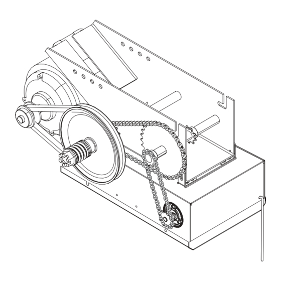
E L E C T R I C A L B O X L O G I C ( V E R 3 . 0 ) For replacement of electrical box, motor or brake components be sure to match model number of your unit to kit number below to ensure proper voltage requirements. - Page 32 M O D E L A P T Drive Chain K3 (K72-13059) K4 (K75-13074) K5 (K72-13058) K2 (K72-13057) K1 (71-AB120)
-
Page 33: Repair Parts Kits
R E P A I R P A R T S K I T S - M O D E L A P T SERVICE KITS INDIVIDUAL PARTS ITEM PART # DESCRIPTION ITEM PART # DESCRIPTION 71-AB120 Brake kit - 115 Volt models 22-120 Brake solenoid, 115V Complete with: Brake solenoid cover,... -
Page 34: Operator Notes
O P E R A T O R N O T E S... -
Page 35: Operator Notes
O P E R A T O R N O T E S... -
Page 36: Control Connection Diagram
OPEN / CLOSE OPEN / CLOSE B2, T, TS & FSTS MODE ONLY Any Commercial Type LiftMaster Brand Receiver See note 2. SENSING DEVICE TO REVERSE OR STOP EXTERNAL INTERLOCK Note: 11 and 4 are both the same common. Remove Factory Installed Jumper Either is acceptable.
Need help?
Do you have a question about the APT and is the answer not in the manual?
Questions and answers