Table of Contents
Advertisement
Available languages
Available languages
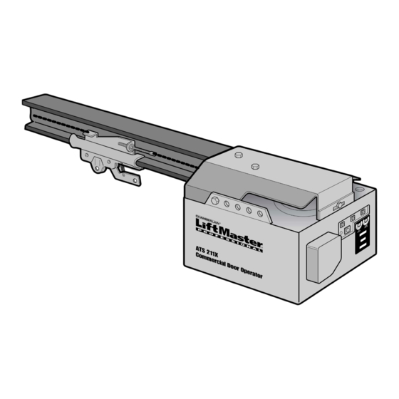
COMMERCIAL DOOR OPENER
Model ATS 211X 1/2 HP
For Residential And Light Duty Commercial Use
Install on Sectional Doors Only
Owner's Manual
■
Please read this manual and the enclosed safety materials carefully!
■
Fasten the manual near the garage door after installation.
■
The door WILL NOT CLOSE unless the Protector System
properly aligned.
■
Periodic checks of the opener are required to ensure safe operation.
■
The model number label is located on the front panel of your opener.
The Chamberlain Group, Inc.
845 Larch Avenue
Elmhurst, Illinois 60126-1196
www.liftmaster.com
®
is connected and
®
Advertisement
Chapters
Table of Contents

Related Manuals for Chamberlain ATS211X


Summary of Contents for Chamberlain ATS211X
- Page 1 The Chamberlain Group, Inc. 845 Larch Avenue Elmhurst, Illinois 60126-1196 www.liftmaster.com ® COMMERCIAL DOOR OPENER Model ATS 211X 1/2 HP For Residential And Light Duty Commercial Use Install on Sectional Doors Only Owner’s Manual ■ Please read this manual and the enclosed safety materials carefully! ■...
-
Page 2: Table Of Contents
TABLE OF CONTENTS Introduction Adjustment 20-22 Safety symbol and signal word review......2 Adjust the travel limits ..........20 Preparing your garage door ........3 Adjust the force ............21 Tools needed ...............3 Test the safety reversal system.........22 Planning ..............4 Test the Protector System ®... -
Page 3: Preparing Your Garage Door
Preparing your garage door WARNING Before you begin: To prevent possible SERIOUS INJURY OR DEATH: • Disable locks. • ALWAYS call a trained door systems technician if CAUTION • Remove any ropes connected to garage door. garage door binds, sticks, or is out of balance. An unbalanced garage door may not reverse when •... -
Page 4: Planning
Planning WARNING Identify the type and height of your garage door. Without a properly working safety reversal system, Survey your garage area to see if any of the persons (particularly small children) could be CAUTION conditions below apply to your installation. Additional SERIOUSLY INJURED or KILLED by a closing garage materials may be required. -
Page 5: Carton Inventory
Carton Inventory Your garage door opener is packaged in two cartons purchased. If anything is missing, carefully check the which contain the motor unit and all parts illustrated packing material. Parts may be stuck in the foam. below. Accessories will depend on the model Hardware for installation is also listed below. -
Page 6: Assembly
WARNING CAUTION ASSEMBLY STEP 1 Attach the Rail to the Motor Unit To avoid SERIOUS damage to opener, ONLY use bolts/fasteners mounted in top of motor unit. To avoid installation difficulties, do not run the garage door opener until instructed to do so. Washered Bolt •... -
Page 7: Tighten The Chain
Lock ASSEMBLY STEP 3 Washer Outer Nut Inner Nut Tighten the Chain To Tighten Outer Nut • Spin the inner nut and lock washer down the To Tighten Inner Nut threaded shaft, away from the trolley. • To tighten the chain, turn outer nut in the direction shown. -
Page 8: Determine The Header Bracket Location
INSTALLATION STEP 1 Determine the Header Bracket Finished Location Ceiling Header Structural Wall WARNING WARNING Supports To prevent possible SERIOUS INJURY or DEATH: • Header bracket MUST be RIGIDLY fastened to CAUTION WARNING structural support on header wall or ceiling, otherwise garage door might not reverse when required. -
Page 9: Install The Header Bracket
INSTALLATION STEP 2 Install the Header Bracket Wall Mounting Holes You can attach the header bracket either to the wall above the garage door, or to the ceiling. Follow the CEILING MOUNT ONLY The nail hole is for positioning only. instructions which will work best for your particular You must use lag screws requirements. -
Page 10: Attach The Rail To The Header Bracket
INSTALLATION STEP 3 Attach the Rail to the Header Bracket • Position the opener on the garage floor below the header bracket. Use packing material as a protective base. NOTE: If the door spring is in the way you’ll need help. Have someone hold the Header Wall opener securely on a temporary support to allow Header... -
Page 11: Position The Opener
WARNING CAUTION INSTALLATION STEP 4 Position the Opener To prevent damage to garage door, rest garage door opener rail on 2x4 placed on top section of door. SECTIONAL DOOR ONLY • If the top section or panel hits the trolley when you A 2x4 laid flat is convenient for setting an ideal raise the door, pull down on the trolley release arm door-to-rail distance. -
Page 12: Install The Door Control
WARNING WARNING CAUTION WARNING INSTALLATION STEP 6 Install the Door Control To prevent possible SERIOUS INJURY or DEATH from electrocution: Locate the door control within sight of the door at a • Be sure power is not connected BEFORE installing door minimum height of 5 feet where small children control. -
Page 13: Install The Light
INSTALLATION STEP 7 75 Watt Max. Light Bulb Install the Light • Install a 75 watt maximum light bulb in the socket. The light will turn ON and remain lit for approximately 4-1/2 minutes when power is connected. Then the light will turn OFF. •... -
Page 14: Electrical Requirements
WARNING WARNING INSTALLATION STEP 9 Electrical Requirements To prevent possible SERIOUS INJURY or DEATH from electrocution or fire: CAUTION WARNING To avoid installation difficulties, do not run the • Be sure power is not connected to the opener, and opener at this time. disconnect power to circuit BEFORE removing cover to To reduce the risk of electric shock, your garage door establish permanent wiring connection. -
Page 15: Install The Protector System
WARNING INSTALLATION STEP 10 Install The Protector System ® • Be sure power is not connected to the garage door opener BEFORE installing the safety reversing sensor. CAUTION The safety reversing sensor must be connected • To prevent SERIOUS INJURY or DEATH from a closing and aligned correctly before the garage door garage door: opener will move in the down direction. - Page 16 INSTALLING THE BRACKETS Figure 1 Figure 1, 2 and 3 show recommended assembly of Garage WALL or DOOR Track Installation bracket(s) and “C” wrap based on the wall Mounting Bracket installation of the sensors on each side of the garage With Square Holes door as shown on page 15, or on the garage door "C"...
-
Page 17: Safety Sensors Troubleshooting
MOUNTING AND WIRING THE SAFETY SENSORS Figure 6 Wing "C" Wrap • Center each sensor unit in a "C" wrap with lenses pointing toward each other across the door Indicator (see Figure 6). Light Sensor • Secure sensors with the hardware shown. Finger with Wire tighten the wing nut on the receiving eye to allow for Hex Bolt... -
Page 18: Fasten The Door Bracket
WARNING CAUTION INSTALLATION STEP 11 Fasten the Door Bracket To prevent damage to garage door, reinforce inside of door with angle iron both vertically and horizontally. A horizontal brace should be long enough to be secured to 2 vertical supports. A vertical brace should cover the height of the top panel. - Page 19 INSTALLATION STEP 12 Inner Trolley Connect Door Arm to Trolley Outer Trolley SECTIONAL DOORS ONLY • Make sure garage door is fully closed. Pull the emergency release handle to disconnect the outer Clevis Pin 5/16"x1" trolley from the inner trolley. Slide the outer trolley Ring Fastener back (away from the door) about 2"...
-
Page 20: Adjustment
WARNING ADJUSTMENT STEP 1 Adjust the UP and DOWN Travel Without a properly installed safety reversal system, Limits persons (particularly small children) could be CAUTION SERIOUSLY INJURED or KILLED by a closing garage Limit adjustment settings regulate the points at which door. -
Page 21: Adjustment
WARNING ADJUSTMENT STEP 2 Adjust the Force Without a properly installed safety reversal system, persons (particularly small children) could be Force adjustment controls are located on the back CAUTION SERIOUSLY INJURED or KILLED by a closing garage panel of the motor unit. Force adjustment settings door. -
Page 22: Test The Safety Reversal System
WARNING ADJUSTMENT STEP 3 Test the Safety Reversal System Without a properly installed safety reversal system, persons (particularly small children) could be CAUTION TEST SERIOUSLY INJURED or KILLED by a closing garage • With the door fully open, place a 1-1/2" board (or a door. -
Page 23: Operation
WARNING OPERATION IMPORTANT SAFETY INSTRUCTIONS WARNING To reduce the risk of severe injury or death: 1. READ AND FOLLOW ALL WARNINGS AND 8. NEVER use handle to pull garage door open or closed. INSTRUCTIONS. If rope knot becomes untied, you could fall. 2. -
Page 24: Using The Wall-Mounted Door Control
Using the Wall-Mounted CARE OF YOUR OPENER Door Control LIMIT AND FORCE ADJUSTMENTS: Press the push button to open or close the door. Press again to reverse the door Weather conditions may during the closing cycle or to stop the cause some minor changes in door while it's opening. -
Page 25: Having A Problem
Having a Problem? 9. The door opens but won't close: • If the opener lights blink, check the safety reversing 1. The opener doesn't operate from either the Door sensor. See Installation Step 10. Control or the remote control: • If the opener lights don’t blink and it is a new installation, •... -
Page 26: Programming
PROGRAMMING Security✚ ® 3-Channel Remote Control Programming (Optional) The 900 Series remote control works only with door WARNING openers and light controls having an orange "Learn" button. To prevent possible SERIOUS INJURY or DEATH from a Programming instructions are described and illustrated moving gate or garage door: CAUTION below. - Page 27 To Add or Change a Keyless Entry PIN (Optional) NOTE: Your new Keyless Entry must be programmed to operate your garage door opener. USING THE “LEARN” BUTTON USING THE MULTI-FUNCTION DOOR CONTROL 1. Press and release the “learn” NOTE: This method requires two people if the Keyless button on motor unit.
-
Page 28: Multi-Function Door Control (Optional)
WARNING WARNING Multi-Function Door Control (Optional) INSTALLATION WARNING CAUTION Locate door control within sight of the door at a minimum height of 5 feet where small children cannot To prevent possible SERIOUS INJURY OR DEATH from reach, and away from moving parts of the door and electrocution: door hardware. -
Page 29: Repair Parts
REPAIR PARTS Rail Assembly Parts PART DESCRIPTION 4A1008 Master link kit 41A2780 Chain pulley bracket 41A3489 Complete trolley assembly CD1008 8 Foot Rail Assembly CD1010 10 Foot Rail Assembly CD1012 12 Foot Rail Assembly CD1014 14 Foot Rail Assembly 83A12 Rail grease NOT SHOWN 41C771... -
Page 30: Motor Unit Assembly Parts
Motor Unit Assembly Parts (Down) LIMIT SWITCH ASSY. Contact Brown Wire Grey Wire Drive Gear Yellow Center Limit (Up) Wire Contact Contact KEY PART KEY PART DESCRIPTION DESCRIPTION 41C5069 Rail support bracket assembly kit 41D4509 Replacement motor & bracket assembly 41B4569 Pulley (Chain) Complete with: Motor, worm,... -
Page 31: Accessories
ACCESSORIES 1702LMC Outside Quick Release: 971LMC 1-Button Security✚ Remote Control: ® Required for a garage with NO Includes visor clip. access door. Enables homeowner to open garage door manually from outside by disengaging trolley. 59LMC 972LMC 2-Button Security✚ ® Remote Control: Outside Keylock: Opens the garage door Includes visor clip. -
Page 32: Warranty
1-800-528-2817 Service number for a list of dealers in your area. LIFTMASTER GARAGE DOOR OPENER ONE-YEAR LIMITED WARRANTY The Chamberlain Group, Inc., (“Seller”) warrants, to the first retail purchaser of this product, for the residence in which this product is originally installed, that it will be free from any defect in materials and/or workmanship for a period of one year from the date of purchase. - Page 33 The Chamberlain Group, Inc. 845 Larch Avenue Elmhurst, Illinois 60126-1196 www.liftmaster.com ® OUVRE-PORTE COMMERCIAL Modéle ATS 211X 1/2 HP Pour usage résidentiel et commercial de petit rendement À n’installer que sur des portes sectionnées Manuel d’instructions ■ Lire attentivement ce manuel ainsi que les consignes de sécurité! ■...
- Page 34 TABLE DES MATIÈRES Introduction Réglages 20-22 Revue des symboles de sécurité et des mots Réglage des courses ......20 de signalement .
-
Page 35: Préparation De Votre Porte De Garage
Préparation de votre porte de garage AVERTISSEMENT Avant de commencer : Pour prévenir d’éventuelles BLESSURES GRAVES OU LA • Désactiver les serrures. MORT : AVERTISSEMENT AVERTIS • TOUJOURS appeler un technicien formé en systèmes de • Retirer toute corde raccordée à la porte de garage. porte si la porte de garage force ou est déséquilibrée. -
Page 36: Planification
Planification AVERTISSEMENT Identifier le type et la hauteur de votre porte de garage. Sans système d’inversion de sécurité en bon état de marche, Examiner la région du garage pour noter si l’une des des personnes (particulièrement les petits enfants) pourraient AVERTISSEMENT AVERTIS conditions ci-après s’applique à... -
Page 37: Inventaire De La Boîte D'emballage
Inventaire de la boîte d’emballage Votre ouvre-porte de garage est emballé dans deux boîtes matériel d’emballage. Les pièces peuvent être coincées qui contiennent le moteur et toutes les pièces illustrées dans la mousse. Les ferrures de montage sont également ci-après. Les accessoires dépendront du modèle acheté. indiquées ci-après. -
Page 38: Montage
AVERTISSEMENT ATTENTION MONTAGE - 1 OPÉRATION Fixation du rail au moteur Afin d’éviter d’endommager SÉRIEUSEMENT l’ouvre-porte de garage, utiliser UNIQUEMENT les boulons et les fixations Pour éviter les difficultés pendant la pose, ne faire montés sur le dessus de l’ouvre-porte. fonctionner l'ouvre-porte de garage que lorsque cela est expressément indiqué. -
Page 39: Tension De La Chaîne
MONTAGE - 3 OPÉRATION Écrou extérieur Rondelle-frein Pour visser Écrou intérieur Tension de la chaîne l'écrou extérieur • Dévisser l'écrou intérieur de la tige filetée du chariot et Pour visser éloigner la rondelle. l'écrou intérieur • Pour tendre la chaîne, tourner l'écrou extérieur dans le sens illustré. -
Page 40: Déterminer L'emplacement Du Support De Linteau
POSE – 1 OPÉRATION Déterminer l’emplacement du support Plafond fini de linteau 2 x 4 Linteau Solives AVERTISSEMENT Pour prévenir d’éventuelles BLESSURES GRAVES ou la MORT : RTISSEMENT AVERTISSEMENT • Le support de linteau DOIT être fixé DE MANIÈRE RIGIDE à la solive sur le linteau ou le plafond, sinon la porte de garage pourrait ne pas remonter au besoin. -
Page 41: Pose Du Support De Linteau
POSE – 2 OPÉRATION Pose du support de linteau Trous de fixation au mur Le support de linteau peut être fixé soit sur le mur, CEILING MOUNT ONLY au-dessus de la porte, soit au plafond. Suivre les Le trou du clou n'est prévu que pour le positionnement instructions qui répondent le mieux aux besoins seulement. -
Page 42: Fixation Du Rail Sur Le Support De Linteau
POSE - 3 OPÉRATION Fixation du rail sur le support de linteau • Positionner l'ouvre-porte de garage sur le plancher, juste sous le support de linteau. Utiliser une des boîtes Linteau d'emballage pour le protéger. REMARQUE : Si le ressort de la porte gêne, il faudra demander de l'aide. Support de linteau Demander à... -
Page 43: Positionnement De L'ouvre-Porte
AVERTISSEMENT ATTENTION POSE - 4 OPÉRATION Positionnement de l'ouvre-porte Pour prévenir les dommages à la porte de garage, faire reposer le rail de l’ouvre-porte de garage sur un 2 x 4 placé sur la SECTIONAL DOOR ONLY section supérieure de la porte. Un 2 x 4 posé... -
Page 44: Pose De La Commande De Porte
AVERTISSEMENT AVERTISSEMENT ATTENTION AVERTISSEMENT POSE - 6 OPÉRATION Pose de la commande de porte Pour prévenir d’éventuelles BLESSURES GRAVES ou la MORT par suite d’électrocution : Poser la commande murale dans un endroit où on pourra la • S’assurer que le courant est coupé AVANT de poser la voir de la porte, à... -
Page 45: Pose De Ampoule
POSE - 7 OPÉRATION Ampoules Pose de ampoule de 75 watts maximum • Visser une ampoule de 75 watts maximum dans chaque douille. Le ampoule s'allumeront et resteront allumées pendant environ 4-1/2 minutes aussitôt que le courant sera établi. • Si l’ampoule brûle prématurément en raison de la vibration, remplacer-la par une ampoule d’ouvre-porte de garage. -
Page 46: Exigences Électriques
AVERTISSEMENT AVERTISSEMENT AVERTISSEMENT POSE - 9 OPÉRATION Exigences électriques Pour prévenir d’éventuelles BLESSURES GRAVES ou la MORT par suite d’électrocution ou d’un incendie : ATTENTION AVERTISSEMENT • S’assurer que l’ouvre-porte est hors tension et couper le Pour éviter les difficultés pendant la pose, ne pas faire courant au circuit AVANT de retirer le couvercle pour fonctionner l'ouvre-porte pour le moment. -
Page 47: Pose Du Système Protector
AVERTISSEMENT POSE - 10 OPÉRATION Pose du Système Protector ® • S’assurer que l’ouvre-porte de garage est hors tension AVANT de poser le détecteur inverseur de sécurité. AVERTISSEMENT AVERTIS Les détecteurs inverseurs de sécurité doivent être bien • Pour prévenir des BLESSURES GRAVES ou la MORT par branchés et bien alignés avant que l'ouvre-porte de suite d’une porte de garage qui se ferme : garage puisse fermer la porte. - Page 48 POSE DES SUPPORTS Figure 1 Installation MURALE ou sur COULISSE de Porte Les Figures 1, 2 et 3 montrent l’assemblage recommandé Support de fixation des supports et du profilé, suivant une installation murale à trous carrés Profilé des détecteurs de chaque côte de la porte du garage tel qu’illustré...
- Page 49 Écrou Figure 6 MONTAGE ET CÂBLAGE DES Profilé à oreilles DÉTECTEURS INVERSEURS • Centrer chaque détecteur sur son profilé en orientant les cellules photo-électriques l'une vers l'autre au travers de Témoin l'ouverture de la porte (voir Figure 6). Capteur • Fixer les détecteurs en place avec les fixations illustrées. avec fil Serrer à...
-
Page 50: Fixation Du Support De Porte
AVERTISSEMENT ATTENTION POSE - 11 OPÉRATION Fixation du support de porte Pour prévenir les dommages à la porte de garage, renforcer l’intérieur de la porte par une cornière tant verticalement Le renfort horizontal doit être suffisamment long de qu’horizontalement. façon à pouvoir être fixé sur 2 supports verticaux. Le renfort vertical doit couvrir toute la hauteur du panneau supérieur. -
Page 51: Fixation De La Biellette Au Chariot
POSE - 12 OPÉRATION Chariot intérieur Fixation de la biellette au chariot PORTE ARTICULÉE SEULEMENT Chariot extérieur • S'assurer que la porte du garage est complètement fermée. Tirer la poignée de déclenchement d’urgence pour détacher le chariot extérieur du chariot intérieur. Axe de chape de 5/16 po x 1 po Reculer le chariot extérieur (en l'éloignant de la porte) -
Page 52: Réglages
AVERTISSEMENT RÉGLAGES - 1 OPÉRATION Réglage des courses d’ouverture Sans un système d’inversion de sécurité bien installé, des et de fermeture AVERTISSEMENT AVERTIS personnes (plus particulièrement les petits enfants) pourraient être GRIÈVEMENT BLESSÉES ou TUÉES par une porte de Le réglage de ces courses fixe les points où la porte garage qui se referme. -
Page 53: Réglage De La Force
RÉGLAGES - 2 OPÉRATION AVERTISSEMENT Réglage de la force Sans un système d’inversion de sécurité bien installé, des personnes (plus particulièrement les petits enfants) pourraient AVERTISSEMENT AVERTIS Les commandes de réglage de la force sont situées sur le être GRIÈVEMENT BLESSÉES ou TUÉES par une porte de panneau droit du moteur. -
Page 54: Essai Du Système Protector
AVERTISSEMENT RÉGLAGES - 3 OPÉRATION Essai du système d’inversion de Sans un système d’inversion de sécurité bien installé, des sécurité personnes (plus particulièrement les petits enfants) pourraient AVERTISSEMENT AVERTIS être GRIÈVEMENT BLESSÉES ou TUÉES par une porte de garage qui se referme. ESSAI •... -
Page 55: Fonctionnement
FONCTIONNEMENT AVERTISSEMENT IMPORTANTES CONSIGNES DE SÉCURITÉ AVERTISSEMENT Pour réduire le risque de blessures graves ou de mort : 1. LIRE ET SUIVRE TOUS LES AVERTISSEMENTS ET 8. Ne JAMAIS utiliser la poignée pour ouvrir ou fermer la porte. INSTRUCTIONS. Il y a risque de chute si le nœud de la corde se défait. 2. -
Page 56: Ouverture Manuelle De La Porte
Utilisation de la commande de ENTRETIEN DE L’OUVRE-PORTE porte à montage mural DE GARAGE Appuyer sur la barre pour ouvrir ou fermer la porte. RÉGLAGES DE COURSE ET DE FORCE : Appuyer à nouveau pour faire remonter la porte lors du cycle de fermeture ou pour arrêter la porte Les conditions climatiques risquent pendant le cycle d'ouverture. -
Page 57: Défauts De Fonctionnement
Défauts de fonctionnement 9. La porte s’ouvre, mais ne se ferme pas : • Si les lumières de l’ouvre-porte clignotent, vérifier le détecteur inverseur de sécurité. Se reporter à la 10 opération de pose. 1. L’ouvre-porte ne fonctionne pas à l’aide de la commande de porte ni de la télécommande : •... -
Page 58: Programmation
CAUTION PROGRAMMATION Programmation du télécommande à trois canaux SECURITY ✚ ® (Facultatif) La télécommande de la série 900 (avec témoin lumineux AVERTISSEMENT AVERTISSEMENT jaune d’essai de pile) fonctionne uniquement avec les ouvre-portes et commandes d’éclairage possédant un bouton Afin d’éliminer les risques de BLESSURES GRAVES ou de MORT «... -
Page 59: De Porte Multifonction (Facultatif)
Pour ajouter ou modifier un NIP d’entrée sans clé (Facultatif) REMARQUE : Votre nouvelle entrée sans clé doit être programmée de manière à faire fonctionner votre ouvre-porte de garage. UTILISATION DU BOUTON « LEARN » UTILISATION DE LA COMMANDE DE PORTE MULTIFONCTION 1. - Page 60 AVERTISSEMENT AVERTISSEMENT AVERTISSEMENT Panneau Commande de Porte (Facultatif) POSE ATTENTION AVERTISSEMENT Poser la commande murale dans un endroit où on pourra la voir de la porte, à au moins 5 pieds du sol, là où les enfants ne pourront pas l'atteindre et loin de toutes les pièces mobiles Pour prévenir d’éventuelles BLESSURES GRAVES ou la MORT par et fixations de la porte.
-
Page 61: Pièces D'assemblage Du Rail
PIÈCES DE RECHANGE Pièces d’assemblage du rail N° DE RÉF. PIÈCE DÉSIGNATION 4A1008 Maillon de raccord 41A2780 Support de poulie de chaîne 41A3489 Chariot complet CD1008 Ensemble rail de 8 pieds CD1010 Ensemble rail de 10 pieds CD1012 Ensemble rail de 12 pieds CD1014 Ensemble rail de 14 pieds 83A12... -
Page 62: Pièces D'assemblage Du Moteur
Pièces d’assemblage du moteur Contact INTERRUPTEUR DE FIN (fermeture) DE COURSE brun gris Pignon menant Contact de fin Contact de course central (d'ouverture) jaune N° DE N° DE RÉF. PIÈCE DÉSIGNATION RÉF. PIÈCE DÉSIGNATION 41C5069 Nécessaure d’assemblage de 41D4509 Ensemble de rechange moteur support et support de montage Comprend: Moteur, vis sans fin,... - Page 63 ACCESSORIES Télécommande à 1 touche avec 1702LMC Détachement rapide d'extérieur : 971LMC Security✚ ® Nécessaire pour un garage SANS Comprend l'agrafe de pare-soleil. porte d'accès. Permet au propriétaire d'ouvrir la porte de garage manuellement à partir de l'extérieur en déconnectant le chariot. Télécommande à...
-
Page 64: Garantie
1-800-528-2817 concessionnaires de votre région. GARANTIE LIMITÉE D’UN AN SUR L'OUVRE-PORTE DE GARAGE LIFTMASTER Chamberlain Group, Inc. («vendeur») garantit, au premier acheteur de détail de ce produit, pour la résidence dans laquelle ce produit a été installé à l’origine, qu’il sera exempt de vices de matériaux et/ou d’exécution pendant un délai d’un an depuis la date d’achat. Le produit doit être utilisé...
Need help?
Do you have a question about the ATS211X and is the answer not in the manual?
Questions and answers