Table of Contents
Advertisement
Quick Links
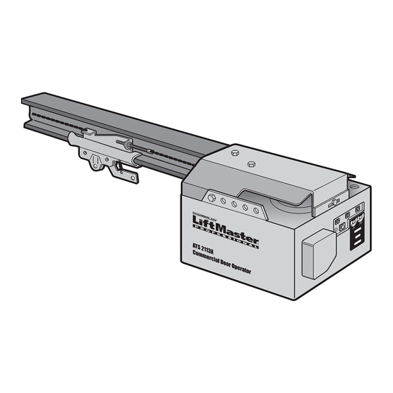
COMMERCIAL DOOR OPENER
Model ATS 2113X 1/2 HP
For Residential And Light Duty Commercial Use
Install on Sectional Doors Only
Owner's Manual
Please read this manual and the enclosed safety materials carefully!
■
Fasten the manual near the garage door after installation.
■
The door WILL NOT CLOSE unless the Protector System
■
properly aligned.
Periodic checks of the opener are required to ensure safe operation.
■
The model number label is located on the front panel of your opener.
■
®
The Chamberlain Group, Inc.
845 Larch Avenue
Elmhurst, Illinois 60126-1196
www.liftmaster.com
®
is connected and
Advertisement
Table of Contents

Related Manuals for Chamberlain ATS 2113X 1/2 HP


Summary of Contents for Chamberlain ATS 2113X 1/2 HP
- Page 1 845 Larch Avenue Elmhurst, Illinois 60126-1196 www.liftmaster.com ® COMMERCIAL DOOR OPENER Model ATS 2113X 1/2 HP For Residential And Light Duty Commercial Use Install on Sectional Doors Only Owner’s Manual Please read this manual and the enclosed safety materials carefully! ■...
-
Page 2: Table Of Contents
TABLE OF CONTENTS Introduction Adjustment 20-22 Safety symbol and signal word review......2 Adjust the travel limits ..........20 Preparing your garage door ........3 Adjust the force ............21 Tools needed ...............3 Test the safety reversal system.........22 Planning ..............4 Test the Protector System ®... -
Page 3: Preparing Your Garage Door
Preparing your garage door WARNING Before you begin: To prevent possible SERIOUS INJURY OR DEATH: • Disable locks. • ALWAYS call a trained door systems technician if CAUTION • Remove any ropes connected to garage door. garage door binds, sticks, or is out of balance. An unbalanced garage door may not reverse when •... -
Page 4: Planning
Planning WARNING Identify the type and height of your garage door. Without a properly working safety reversal system, Survey your garage area to see if any of the persons (particularly small children) could be CAUTION conditions below apply to your installation. Additional SERIOUSLY INJURED or KILLED by a closing garage materials may be required. -
Page 5: Carton Inventory
Carton Inventory Your garage door opener is packaged in two cartons purchased. If anything is missing, carefully check the which contain the motor unit and all parts illustrated packing material. Parts may be stuck in the foam. below. Accessories will depend on the model Hardware for installation is also listed below. -
Page 6: Attach The Rail To The Motor Unit
WARNING CAUTION ASSEMBLY STEP 1 Attach the Rail to the Motor Unit To avoid SERIOUS damage to opener, ONLY use bolts/fasteners mounted in top of motor unit. To avoid installation difficulties, do not run the garage door opener until instructed to do so. Washered Bolt •... -
Page 7: Tighten The Chain
ASSEMBLY STEP 3 Lock Washer Outer Nut Inner Nut Tighten the Chain To Tighten Outer Nut • Spin the inner nut and lock washer down the To Tighten Inner Nut threaded shaft, away from the trolley. • To tighten the chain, turn outer nut in the direction shown. -
Page 8: Determine The Header Bracket Location
INSTALLATION STEP 1 Determine the Header Bracket Unfinished OPTIONAL Ceiling Location CEILING MOUNT HEADER WARNING WARNING BRACKET Header Wall To prevent possible SERIOUS INJURY or DEATH: Vertical Centerline • Header bracket MUST be RIGIDLY fastened to CAUTION of Garage Door WARNING structural support on header wall or ceiling, otherwise Structural... -
Page 9: Install The Header Bracket
INSTALLATION STEP 2 Install the Header Bracket Wall Mounting Holes You can attach the header bracket either to the wall CEILING MOUNT ONLY The nail hole is for above the garage door, or to the ceiling. Follow the positioning only. instructions which will work best for your particular You must use lag screws to mount the header bracket. -
Page 10: Attach The Rail To The Header Bracket
INSTALLATION STEP 3 Attach the Rail to the Header Bracket • Position the opener on the garage floor below the header bracket. Use packing material as a protective base. NOTE: If the door spring is in the way you’ll need help. Have someone hold the Header Wall opener securely on a temporary support to allow Header... -
Page 11: Position The Opener
WARNING CAUTION INSTALLATION STEP 4 Position the Opener To prevent damage to garage door, rest garage door opener rail on 2x4 placed on top section of door. SECTIONAL DOOR ONLY A 2x4 laid flat is convenient for setting an ideal •... -
Page 12: Install The Door Control
WARNING WARNING CAUTION WARNING INSTALLATION STEP 6 Install the Door Control To prevent possible SERIOUS INJURY or DEATH from electrocution: Locate the door control within sight of the door at a • Be sure power is not connected BEFORE installing door minimum height of 5 feet (1.5 m) where small control. -
Page 13: Install The Light
WARNING INSTALLATION STEP 7 CAUTION Install the Light To prevent possible OVERHEATING of the endpanel or light socket, • Install a 75 watt maximum light bulb in the socket. • DO NOT use short neck or specialty light bulbs. The light will turn ON and remain lit for •... -
Page 14: Electrical Requirements
WARNING WARNING INSTALLATION STEP 9 Electrical Requirements To prevent possible SERIOUS INJURY or DEATH from electrocution or fire: CAUTION WARNING To avoid installation difficulties, do not run the • Be sure power is not connected to the opener, and opener at this time. disconnect power to circuit BEFORE removing cover to To reduce the risk of electric shock, your garage door establish permanent wiring connection. -
Page 15: Install The Protector System
WARNING INSTALLATION STEP 10 Install The Protector System ® • Be sure power is not connected to the garage door opener BEFORE installing the safety reversing sensor. CAUTION The safety reversing sensor must be connected • To prevent SERIOUS INJURY or DEATH from a closing and aligned correctly before the garage door garage door: opener will move in the down direction. - Page 16 INSTALLING THE BRACKETS Figure 1 Garage WALL or DOOR Track Installation Figure 1, 2 and 3 show recommended assembly of bracket(s) and “C” wrap based on the wall Mounting Bracket With Square Holes installation of the sensors on each side of the garage “C”...
-
Page 17: Safety Sensors Troubleshooting
MOUNTING AND WIRING THE SAFETY SENSORS Figure 6 Wing "C" Wrap • Center each sensor unit in a “C” wrap with lenses pointing toward each other across the door (see Figure 6). Indicator Light • Secure sensors with the hardware shown. Finger Sensor tighten the wing nut on the receiving eye to allow for with Wire... -
Page 18: Fasten The Door Bracket
WARNING CAUTION INSTALLATION STEP 11 Fasten the Door Bracket Fiberglass, aluminum or lightweight steel garage doors WILL REQUIRE reinforcement BEFORE installation of A horizontal brace should be long enough to be door bracket. Contact your door manufacturer for secured to 2 vertical supports. A vertical brace reinforcement kit. -
Page 19: Connect The Door Arm To The Trolley
INSTALLATION STEP 12 Inner Trolley Connect Door Arm to Trolley Outer Trolley SECTIONAL DOORS ONLY • Make sure garage door is fully closed. Pull the emergency release handle to disconnect the outer Clevis Pin 5/16"x1" trolley from the inner trolley. Slide the outer trolley Ring Fastener back (away from the door) about 2"... -
Page 20: Adjust The Travel Limits
WARNING ADJUSTMENT STEP 1 Adjust the UP and DOWN Travel Without a properly installed safety reversal system, Limits persons (particularly small children) could be CAUTION SERIOUSLY INJURED or KILLED by a closing garage Limit adjustment settings regulate the points at which door. -
Page 21: Adjustment
WARNING ADJUSTMENT STEP 2 Adjust the Force Without a properly installed safety reversal system, persons (particularly small children) could be Force adjustment controls are located on the back CAUTION SERIOUSLY INJURED or KILLED by a closing garage panel of the motor unit. Force adjustment settings door. -
Page 22: Test The Safety Reversal System
WARNING ADJUSTMENT STEP 3 Test the Safety Reversal System Without a properly installed safety reversal system, persons (particularly small children) could be CAUTION TEST SERIOUSLY INJURED or KILLED by a closing garage • With the door fully open, place a 1-1/2" (3.8 cm) door. -
Page 23: Operation
WARNING OPERATION IMPORTANT SAFETY INSTRUCTIONS WARNING To reduce the risk of SEVERE INJURY or DEATH: 1. READ AND FOLLOW ALL WARNINGS AND 9. If one control (force or travel limits) is adjusted, the INSTRUCTIONS. other control may also need adjustment. 2. -
Page 24: Using The Wall-Mounted Door Control
Using the Wall-Mounted CARE OF YOUR OPENER Door Control LIMIT AND FORCE ADJUSTMENTS: Press the push button to open or close the door. Press again to reverse the door Weather conditions may FORCE CONTROLS during the closing cycle or to stop the cause some minor changes in door while it’s opening. -
Page 25: Having A Problem
Having a Problem? 9. The door opens but won’t close: • If the opener lights blink, check the safety reversing 1. The opener doesn’t operate from either the Door sensor. See Installation Step 10. Control or the remote control: • If the opener lights don’t blink and it is a new installation, •... -
Page 26: Programming
PROGRAMMING NOTICE: If this Security ✚ garage door opener is operated with a non-rolling code transmitter, the technical ® measure in the receiver of the garage door opener, which provides security against code-theft devices, will be circumvented. The owner of the copyright in the garage door opener does not authorize the purchaser or supplier of the non-rolling code transmitter to circumvent that technical measure. -
Page 27: To Add Or Change A Keyless Entry Pin (Optional)
To Add or Change a Keyless Entry PIN (Optional) NOTE: Your new Keyless Entry must be programmed to operate your garage door opener. USING THE “LEARN” BUTTON To change an existing, known PIN If the existing PIN is known, it may be changed by one person without using a ladder. -
Page 28: Multi-Function Door Control (Optional)
WARNING WARNING Multi-Function Door Control (Optional) INSTALLATION CAUTION WARNING Locate door control within sight of the door at a minimum height of 5 feet (1.5 m) where small children cannot To prevent possible SERIOUS INJURY OR DEATH from reach, and away from moving parts of the door and door electrocution: hardware. -
Page 29: Repair Parts
REPAIR PARTS Rail Assembly Parts PART DESCRIPTION 4A1008 Master link kit 41A2780 Chain pulley bracket 41A3489 Complete trolley assembly CD1008 8 Foot (2.44 m) Rail Assy. CD1010 10 Foot (3.05 m) Rail Assy. CD1012 12 Foot (3.66 m) Rail Assy. CD1014 14 Foot (4.27 m) Rail Assy. -
Page 30: Motor Unit Assembly Parts
Motor Unit Assembly Parts (Down) LIMIT SWITCH ASSY. Contact Brown Wire Grey Wire Drive Gear Yellow Center Limit (Up) Wire Contact Contact KEY PART KEY PART DESCRIPTION DESCRIPTION 41C5069 Rail support bracket assembly kit 41D4509 Replacement motor & bracket assembly 41B4569 Pulley (Chain) Complete with: Motor, worm,... -
Page 31: Accessories
ACCESSORIES 1702LM SECURITY✚ Outside Quick Release: 371LM ® 1-Button Remote Control: Required for a garage with NO access door. Enables Includes visor clip. homeowner to open garage door manually from outside by disengaging trolley. SECURITY✚ 59LM ® 372LM 2-Button Outside Keylock: Remote Control: Opens the garage door automatically from outside when... -
Page 32: Repair Parts And Service
LIFETIME MOTOR LIMITED WARRANTY The Chamberlain Group, Inc. (“Seller”) warrants to the first retail purchaser of this product, for the residence in which this product is originally installed, that it is free from defect in materials and/or workmanship for a period of one year from the date of purchase [and that the motor is free from defect in materials and/or workmanship for the lifetime of the product].
Need help?
Do you have a question about the ATS 2113X 1/2 HP and is the answer not in the manual?
Questions and answers