Table of Contents
Advertisement
Available languages
Available languages
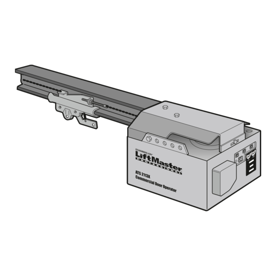
COMMERCIAL DOOR OPENER
Model ATS 211X 1/2 HP
For Residential And Light Duty Commercial Use
Install on Sectional Doors Only
Owner's Manual
■
Please read this manual and the enclosed safety materials carefully!
■
Fasten the manual near the garage door after installation.
■
The door WILL NOT CLOSE unless the Protector System
properly aligned.
■
Periodic checks of the opener are required to ensure safe operation.
■
The model number label is located on the front panel of your opener.
®
The Chamberlain Group, Inc.
845 Larch Avenue
Elmhurst, Illinois 60126-1196
www.liftmaster.com
®
is connected and
Advertisement
Chapters
Table of Contents

Related Manuals for Chamberlain ATS 211X 1/2 HP


Summary of Contents for Chamberlain ATS 211X 1/2 HP
- Page 1 COMMERCIAL DOOR OPENER Model ATS 211X 1/2 HP For Residential And Light Duty Commercial Use Install on Sectional Doors Only Owner’s Manual ■ Please read this manual and the enclosed safety materials carefully! ■ Fasten the manual near the garage door after installation.
-
Page 2: Table Of Contents
Safety Symbol and Signal Word Review This garage door opener has been designed and tested to offer safe service provided it is installed, operated, maintained and tested in strict accordance with the instructions and warnings contained in this manual. WARNING... -
Page 3: Preparing Your Garage Door
To prevent damage to garage door and opener: • ALWAYS disable locks BEFORE installing and operating the opener. • ONLY operate garage door opener at 120V, 60 Hz to avoid malfunction and damage. Tools needed During assembly, installation and adjustment of the opener, instructions will call for hand tools as illustrated below. -
Page 4: Planning
Planning Identify the type and height of your garage door. Survey your garage area to see if any of the conditions below apply to your installation. Additional materials may be required. You may find it helpful to refer back to this page and the accompanying illustrations as you proceed with the installation of your opener. -
Page 5: Carton Inventory
Carton Inventory Your garage door opener is packaged in two cartons which contain the motor unit and all parts illustrated below. Accessories will depend on the model Mounting Hardware Rail Support (Rail Support Bracket) Bracket Door Bracket "C" Wrap (2) -
Page 6: Assembly
ASSEMBLY STEP 1 Attach the Rail to the Motor Unit To avoid installation difficulties, do not run the garage door opener until instructed to do so. • Place the opener on packing material to protect the cover. • Remove the (2) 5/16"-18x1/2" washered bolts mounted in the top of the motor unit. -
Page 7: Assembly
4. Disable all locks and remove ALL ropes connected to garage door BEFORE installing opener to avoid entanglement. 5. Install garage door opener 7 feet or more above floor. 6. Mount emergency release handle 6 feet above floor. 7. NEVER connect garage door opener to power source until instructed to do so. -
Page 8: Installation Step
INSTALLATION STEP 1 Determine the Header Bracket Location WARNING To prevent possible SERIOUS INJURY or DEATH: • Header bracket MUST be RIGIDLY fastened to CAUTION structural support on header wall or ceiling, otherwise garage door might not reverse when required. DO NOT install header bracket over drywall. -
Page 9: Install The Header Bracket
INSTALLATION STEP 2 Install the Header Bracket You can attach the header bracket either to the wall above the garage door, or to the ceiling. Follow the instructions which will work best for your particular requirements. Do not install the header bracket over drywall. -
Page 10: Attach The Rail To The Header Bracket
Header Wall Header Bracket Chain Pulley Bracket Rail Garage Door HARDWARE SHOWN ACTUAL SIZE Clevis Pin 5/16"x2-3/4" INSTALLATION STEP 3 Attach the Rail to the Header Bracket • Position the opener on the garage floor below the header bracket. Use packing material as a protective base. -
Page 11: Position The Opener
INSTALLATION STEP 4 Position the Opener SECTIONAL DOOR ONLY A 2x4 laid flat is convenient for setting an ideal door-to-rail distance. • Remove foam packaging. • Raise the opener onto a stepladder. You will need help at this point if the ladder is not tall enough. •... -
Page 12: Install The Door Control
CAUTION INSTALLATION STEP 6 Install the Door Control Locate the door control within sight of the door at a minimum height of 5 feet where small children cannot reach, and away from all moving parts of the door and door hardware. 1. -
Page 13: Install The Light
4-1/2 minutes when power is connected. Then the lights will turn OFF. • Reverse the procedure to close the lens. • Use A19, standard neck garage door opener bulbs for replacement. NOTE: Use only standard light bulbs. The use of short neck or speciality light bulbs may overheat the endpanel or light socket. -
Page 14: Electrical Requirements
WARNING INSTALLATION STEP 9 Electrical Requirements CAUTION To avoid installation difficulties, do not run the opener at this time. To reduce the risk of electric shock, your garage door opener has a grounding type plug with a third grounding pin. This plug will only fit into a grounding type outlet. -
Page 15: Install The Protector System
INSTALLATION STEP 10 Install The Protector System The safety reversing sensor must be connected and aligned correctly before the garage door opener will move in the down direction. IMPORTANT INFORMATION ABOUT THE SAFETY REVERSING SENSOR When properly connected and aligned, the sensor will detect an obstacle in the path of its electronic beam. -
Page 16: Installing The Brackets
INSTALLING THE BRACKETS Figure 1, 2 and 3 show recommended assembly of bracket(s) and “C” wrap based on the wall installation of the sensors on each side of the garage door as shown on page 15, or on the garage door tracks themselves. -
Page 17: Mounting And Wiring The Safety Reversing Sensors
MOUNTING AND WIRING THE SAFETY REVERSING SENSORS • Center each sensor unit in a "C" wrap with lenses pointing toward each other across the door (see Figure 6). • Secure sensors with the hardware shown. Finger tighten the wing nut on the receiving eye to allow for final adjustment. -
Page 18: Fasten The Door Bracket
INSTALLATION STEP 11 Fasten the Door Bracket A horizontal brace should be long enough to be secured to 2 vertical supports. A vertical brace should cover the height of the top panel. The illustration shows one piece of angle iron as the horizontal brace. -
Page 19: Connect Door Arm To Trolley
INSTALLATION STEP 12 Connect Door Arm to Trolley SECTIONAL DOORS ONLY • Make sure garage door is fully closed. Pull the emergency release handle to disconnect the outer trolley from the inner trolley. Slide the outer trolley back (away from the door) about 2" as shown in Figures 1, 2 and 3. -
Page 20: Adjustment
ADJUSTMENT STEP 1 Adjust the UP and DOWN Travel Limits Limit adjustment settings regulate the points at which the door will stop when moving up or down. To operate the opener, press the Door Control push bar. Run the opener through a complete travel cycle. •... -
Page 21: Adjustment
ADJUSTMENT STEP 2 Adjust the Force Force adjustment controls are located on the back panel of the motor unit. Force adjustment settings regulate the amount of power required to open and close the door. If the forces are set too light, door travel may be interrupted by nuisance reversals in the down direction and stops in the up direction. -
Page 22: Test The Safety Reversal System
The door will not move more than an inch, and the opener lights will flash. The garage door opener will not close from a remote if the indicator light in either sensor is off (alerting you to the fact that the sensor is misaligned or obstructed). -
Page 23: Operation
• The wall-mounted Door Control: Hold the push button or bar down until the door starts to move. • The Keyless Entry (See Accessories): If provided with your garage door opener, it must be programmed before use. See Programming. When the opener is activated (with the safety reversing sensor correctly installed and aligned) 1. -
Page 24: Using The Wall-Mounted Door Control
Using the Wall-Mounted Door Control Press the push button to open or close the door. Press again to reverse the door during the closing cycle or to stop the door while it's opening. To Open the Door Manually WARNING To prevent possible SERIOUS INJURY or DEATH from a falling garage door: CAUTION •... -
Page 25: Having A Problem
Step 10. 12. The opener lights don't turn on: • Replace the light bulbs (75 watts maximum). Use only A19 standard neck garage door opener bulb if regular bulb burns out. 13. The opener lights don't turn off: • Is the Light feature on? Turn it off. -
Page 26: Programming
PROGRAMMING Security✚ ® 3-Channel Remote Control Programming (Optional) The 900 Series remote control works only with door openers and light controls having an orange "Learn" button. Programming instructions are described and illustrated below. The additional push buttons can also activate other garage door openers and/or light controls. -
Page 27: To Add Or Change A Keyless Entry Pin (Optional)
To Add or Change a Keyless Entry PIN (Optional) NOTE: Your new Keyless Entry must be programmed to operate your garage door opener. USING THE “LEARN” BUTTON 1. Press and release the “learn” button on motor unit. The learn indicator light will glow steadily for 30 seconds. -
Page 28: Multi-Function Door Control (Optional)
WARNING Multi-Function Door Control (Optional) INSTALLATION CAUTION Locate door control within sight of the door at a minimum height of 5 feet where small children cannot reach, and away from moving parts of the door and door hardware. If installing into drywall, drill 5/32" holes and use anchors provided. -
Page 29: Repair Parts
REPAIR PARTS Rail Assembly Parts Installation Parts PART 4A1008 41A2780 41A3489 CD1008 CD1010 CD1012 CD1014 83A12 41C771 PART 41A4166 41B4494-1 41A2828 12B374 12B380 41A4353 41A4373A 178B35 12B483 178B34 178B73 12B484 12B485 41A2770 41A4116 114A2709 DESCRIPTION Master link kit Chain pulley bracket Complete trolley assembly 8 Foot Rail Assembly 10 Foot Rail Assembly... -
Page 30: Motor Unit Assembly Parts
Motor Unit Assembly Parts (Down) LIMIT SWITCH ASSY. Contact Brown Wire Drive Gear Center Limit (Up) Contact Contact KEY PART DESCRIPTION 41C5069 Rail support bracket assembly kit 41B4569 Pulley (Chain) 41A5668 Gear and sprocket assy. Complete with: Spring washer, thrust washer, retaining washer, bearing plate roll pins (2), drive gear and worm gear, helical gear... -
Page 31: Accessories
ACCESSORIES 1702LMC Outside Quick Release: Required for a garage with NO access door. Enables homeowner to open garage door manually from outside by disengaging trolley. 59LMC Outside Keylock: Opens the garage door automatically from outside when remote control is not handy. 180C139 NEMA 1 Push Button: Heavy Duty Door Control Push... -
Page 32: How To Order Repair Parts
LIFTMASTER The Chamberlain Group, Inc. (“Seller”) warrants to the first retail purchaser of this product, for the residence in which this product is originally installed, that it is free from defect in materials and/or workmanship for a period of one year from the date of purchase [and that the motor is free from defect in materials and/or workmanship for the lifetime of the product]. -
Page 33: Manuel D'instructions
OUVRE-PORTE COMMERCIAL Modéle ATS 211X 1/2 HP Pour usage résidentiel et commercial de petit rendement À n’installer que sur des portes sectionnées Manuel d’instructions ■ Lire attentivement ce manuel ainsi que les consignes de sécurité! ■ Après la pose, accrocher ce manuel près de la porte de garage pour s’y reporter ultérieurement. - Page 34 TABLE DES MATIÈRES Introduction Revue des symboles de sécurité et des mots de signalement ........2 Préparation de votre porte de garage .
-
Page 35: Préparation De Votre Porte De Garage
Préparation de votre porte de garage Avant de commencer : • Désactiver les serrures. • Retirer toute corde raccordée à la porte de garage. • Réaliser le test suivant pour s’assurer que la porte de garage est équilibrée et qu’elle ne force pas : 1. -
Page 36: Planification
Planification Identifier le type et la hauteur de votre porte de garage. Examiner la région du garage pour noter si l’une des conditions ci-après s’applique à votre installation. Des matériaux supplémentaires peuvent être nécessaires. Il vous sera peut-être utile de vous reporter à cette page et aux illustrations qui l’accompagnent en procédant à... -
Page 37: Inventaire Des Fixations
Inventaire de la boîte d’emballage Votre ouvre-porte de garage est emballé dans deux boîtes qui contiennent le moteur et toutes les pièces illustrées ci-après. Les accessoires dépendront du modèle acheté. S’il manque quoi que ce soit, vérifier soigneusement le Visserie (Support du rail) Tasseau de support du rail Support de la porte... -
Page 38: Montage
MONTAGE - 1 OPÉRATION Fixation du rail au moteur Pour éviter les difficultés pendant la pose, ne faire fonctionner l'ouvre-porte de garage que lorsque cela est expressément indiqué. • Poser l'ouvre-porte sur une des boîtes d'emballage pour protéger le couvercle. •... -
Page 39: Tension De La Chaîne
MONTAGE - 3 OPÉRATION Tension de la chaîne • Dévisser l'écrou intérieur de la tige filetée du chariot et éloigner la rondelle. • Pour tendre la chaîne, tourner l'écrou extérieur dans le sens illustré. Alors que l'on tourne l'écrou, empêcher la chaîne de vriller. -
Page 40: Déterminer L'emplacement Du Support De Linteau
POSE – 1 OPÉRATION Déterminer l’emplacement du support de linteau AVERTISSEMENT Pour prévenir d’éventuelles BLESSURES GRAVES ou la MORT : • Le support de linteau DOIT être fixé DE MANIÈRE RIGIDE à la solive sur le linteau ou le plafond, sinon la porte de garage pourrait ne pas remonter au besoin. -
Page 41: Pose Du Support De Linteau
POSE – 2 OPÉRATION Pose du support de linteau Le support de linteau peut être fixé soit sur le mur, au-dessus de la porte, soit au plafond. Suivre les instructions qui répondent le mieux aux besoins particuliers. Ne pas poser le support de linteau sur des panneaux de placoplâtre. -
Page 42: Fixation Du Rail Sur Le Support De Linteau
Linteau Support de linteau Support de la poulie de la chaîne Rail Porte de garage GRANDEUR RÉELLE DES FIXATIONS Axe de chape de 5/16 po x 2-3/4 po POSE - 3 OPÉRATION Fixation du rail sur le support de linteau •... -
Page 43: Positionnement De L'ouvre-Porte
POSE - 4 OPÉRATION Positionnement de l'ouvre-porte SECTIONAL DOOR ONLY Un 2 x 4 posé à plat convient très bien pour obtenir l'espace qu'il faut entre la porte et le rail. • Enlever l’emballage en mousse. • Lever l'ouvre-porte et le faire reposer sur un escabeau. Si l'escabeau n'est pas assez haut, demander de l'aide. -
Page 44: Pose De La Commande De Porte
ATTENTION POSE - 6 OPÉRATION Pose de la commande de porte Poser la commande murale dans un endroit où on pourra la voir de la porte, à au moins 5 pieds du sol, là où les enfants ne pourront pas l'atteindre et loin de toutes les pièces mobiles et fixations de la porte. -
Page 45: Pose De Ampoule
POSE - 7 OPÉRATION Pose de ampoule • Visser une ampoule de 75 watts maximum dans chaque douille. La taille Légère d’ampoule doit être A19, seulement. Le ampoule s'allumeront et resteront allumées pendant environ 4-1/2 minutes aussitôt que le courant sera établi. •... -
Page 46: Exigences Électriques
AVERTISSEMENT POSE - 9 OPÉRATION Exigences électriques ATTENTION Pour éviter les difficultés pendant la pose, ne pas faire fonctionner l'ouvre-porte pour le moment. Afin de minimiser les risques de chocs électriques, le cordon d'alimentation de l'ouvre-porte de garage comporte une fiche à trois broches, dont une de mise à la terre. Cette fiche ne peut être branchée que dans une prise de courant mise à... -
Page 47: Pose Du Système Protector
POSE - 10 OPÉRATION Pose du Système Protector Les détecteurs inverseurs de sécurité doivent être bien branchés et bien alignés avant que l'ouvre-porte de garage puisse fermer la porte. INFORMATIONS IMPORTANTES AU SUJET DU DÉTECTEUR INVERSEUR DE SÉCURITÉ Lorsqu’il est bien raccordé et aligné, le détecteur détecte un obstacle dans le parcours de son faisceau électronique. - Page 48 POSE DES SUPPORTS Les Figures 1, 2 et 3 montrent l’assemblage recommandé des supports et du profilé, suivant une installation murale des détecteurs de chaque côte de la porte du garage tel qu’illustré en page 15 ou sur les coulisses mêmes de la porte du garage.
- Page 49 MONTAGE ET CÂBLAGE DES DÉTECTEURS INVERSEURS DE SÉCURITÉ • Centrer chaque détecteur sur son profilé en orientant les cellules photo-électriques l'une vers l'autre au travers de l'ouverture de la porte (voir Figure 6). • Fixer les détecteurs en place avec les fixations illustrées. Serrer à...
-
Page 50: Fixation Du Support De Porte
POSE - 11 OPÉRATION Fixation du support de porte Le renfort horizontal doit être suffisamment long de façon à pouvoir être fixé sur 2 supports verticaux. Le renfort vertical doit couvrir toute la hauteur du panneau supérieur. L'illustration montre un morceau de cornière utilisé en tant que renfort horizontal. -
Page 51: Fixation De La Biellette Au Chariot
POSE - 12 OPÉRATION Fixation de la biellette au chariot PORTE ARTICULÉE SEULEMENT • S'assurer que la porte du garage est complètement fermée. Tirer la poignée de déclenchement d’urgence pour détacher le chariot extérieur du chariot intérieur. Reculer le chariot extérieur (en l'éloignant de la porte) d'environ 2 pouces, comme illustré... -
Page 52: Réglages
RÉGLAGES - 1 OPÉRATION Réglage des courses d’ouverture et de fermeture Le réglage de ces courses fixe les points où la porte s'arrêtera lors de son ouverture ou de sa fermeture. Pour faire fonctionner l'ouvre-porte, appuyer sur le bouton-poussoir de la commande de porte. Faire faire un cycle complet à... -
Page 53: Réglage De La Force
RÉGLAGES - 2 OPÉRATION Réglage de la force Les commandes de réglage de la force sont situées sur le panneau droit du moteur. Elles servent à régler la puissance du courant nécessaire à l'ouverture et à la fermeture de la porte. Si la force réglée est trop faible, la porte aura tendance à... -
Page 54: Essai Du Système Protector
RÉGLAGES - 3 OPÉRATION Essai du système d’inversion de sécurité ESSAI • La porte étant entièrement ouverte, placer une planche de 1-1/2 po d’épaisseur (ou un 2 x 4 à plat) sur le plancher, centrée sous la porte de garage. •... -
Page 55: Fonctionnement
FONCTIONNEMENT IMPORTANTES CONSIGNES DE SÉCURITÉ Pour réduire le risque de BLESSURES GRAVES 1. LIRE ET SUIVRE TOUS LES AVERTISSEMENTS ET INSTRUCTIONS. 2. TOUJOURS garder les télécommandes hors de la portée des enfants. Ne JAMAIS laisser les enfants faire fonctionner les télécommandes ou les boutons-poussoirs de la commande de porte ou jouer avec ceux-ci. -
Page 56: Ouverture Manuelle De La Porte
Utilisation de la commande de porte à montage mural Appuyer sur la barre pour ouvrir ou fermer la porte. Appuyer à nouveau pour faire remonter la porte lors du cycle de fermeture ou pour arrêter la porte pendant le cycle d'ouverture. Ouverture manuelle de la porte AVERTISSEMENT Pour prévenir d’éventuelles BLESSURES GRAVES ou la MORT... -
Page 57: Défauts De Fonctionnement
Défauts de fonctionnement 1. L’ouvre-porte ne fonctionne pas à l’aide de la commande de porte ni de la télécommande : • Le courant électrique parvient-il à l’ouvre-porte? Brancher une lampe dans la prise de courant. Si elle ne s’allume pas, vérifier les fusibles ou le disjoncteur. -
Page 58: Programmation
PROGRAMMATION Programmation du télécommande à trois canaux SECURITY ✚ La télécommande de la série 900 (avec témoin lumineux jaune d’essai de pile) fonctionne uniquement avec les ouvre-portes et commandes d’éclairage possédant un bouton « learn » orange et un témoin lumineux jaune. Des instructions de programmation sont décrites et illustrées ci-après. -
Page 59: De Porte Multifonction (Facultatif)
Pour ajouter ou modifier un NIP d’entrée sans clé (Facultatif) REMARQUE : Votre nouvelle entrée sans clé doit être programmée de manière à faire fonctionner votre ouvre-porte de garage. UTILISATION DU BOUTON « LEARN » 1. Enfoncer et tenir le bouton « learn » sur le moteur. - Page 60 AVERTISSEMENT Panneau Commande de Porte (Facultatif) POSE ATTENTION Poser la commande murale dans un endroit où on pourra la voir de la porte, à au moins 5 pieds du sol, là où les enfants ne pourront pas l'atteindre et loin de toutes les pièces mobiles et fixations de la porte.
-
Page 61: Pièces De Rechange
PIÈCES DE RECHANGE Pièces d’assemblage du rail Pièces pour la pose N° DE RÉF. PIÈCE 4A1008 41A2780 41A3489 CD1008 CD1010 CD1012 CD1014 83A12 41C771 N° DE RÉF. PIÈCE 41A4166 41B4494-1 41A2828 12B374 12B380 41A4353 41A4373A 178B35 12B483 178B34 178B73 12B484 12B485 41A2770 41A4116... -
Page 62: Pièces D'assemblage Du Moteur
Pièces d’assemblage du moteur Contact INTERRUPTEUR DE FIN (fermeture) brun Pignon menant Contact de fin Contact de course central (d'ouverture) N° DE RÉF. PIÈCE DÉSIGNATION 41C5069 Nécessaure d’assemblage de support 41B4569 Poulie 41A5668 Pignon et engrenage. Comprend : Rondelle-frein, rondelle de butée, rondelle de retenue, plaque de butée goupille cylindrique (2), pignon menant et vis sans fin,... - Page 63 ACCESSORIES 1702LMC Détachement rapide d'extérieur : Nécessaire pour un garage SANS porte d'accès. Permet au propriétaire d'ouvrir la porte de garage manuellement à partir de l'extérieur en déconnectant le chariot. 59LMC Serrure extérieure : Pour ouvrir automatiquement la porte du garage de l’extérieur sans l’émetteur.
-
Page 64: Comment Commander Des Pièces De Rechange
GARANTIE LIMITÉE D’UN AN SUR L'OUVRE-PORTE DE GARAGE LIFTMASTER Chamberlain Group, Inc. («vendeur») garantit, au premier acheteur de détail de ce produit, pour la résidence dans laquelle ce produit a été installé à l’origine, qu’il sera exempt de vices de matériaux et/ou d’exécution pendant un délai d’un an depuis la date d’achat. Le produit doit être utilisé...
Need help?
Do you have a question about the ATS 211X 1/2 HP and is the answer not in the manual?
Questions and answers