ACT ACTENTRY V-IP Operating And Installation Instructions
Hide thumbs
Also See for ACTENTRY V-IP:
- Datasheet (2 pages) ,
- Operating and installtion instructions (30 pages)
Table of Contents
Advertisement
Quick Links
Advertisement
Table of Contents

Subscribe to Our Youtube Channel
Related Manuals for ACT ACTENTRY V-IP


Summary of Contents for ACT ACTENTRY V-IP
- Page 1 ACTentry V-IP Operating & Installation Instructions 18-00068...
- Page 2 Access Control Technologies Ltd. reserve the right to change the contents of this manual and the system it applies to without prior notice. While every effort has been taken by ACT to ensure the accuracy of the information contained within this document, ACT assumes no responsibility for any errors or omissions.
-
Page 3: Table Of Contents
3.0 OPERATION ......................16 4.0 TROUBLESHOOTING ....................17 5.0 SETTING FIXED IP ADDRESS ................20 6.0 DIAGRAMS Installing ACTentry V-IP unit and ACTentry V-IP door panel........22 ACTpro-x 1030 panel mount reader installation............23 ACTentry V-IP Waterproofing .................. 24 Ordering Information... -
Page 4: Introduction
ACTentry V-IP Operating and Installation Manual 1.0 INTRODUCTION 1.1 System Overview The ACTentry V-IP (Video/audio over IP) system is a TCP/IP based video- doorphone system. Access to the building can be administered from any PC on the TCP/IP network. The system consists of: 1. -
Page 5: Product Specification
ACTentry V-IP Operating and Installation Manual 1.2 Product Specification Number of PC’s 10 maximum Number of Doors 8 maximum (each door with individual Door Panel and V-IP unit) Supply Voltage 10-15Volts DC Current Consumption 450mA nominal, 500mA maximum Operating Temperature... -
Page 6: Installing Actentry V-Ip Door Panel
ACTentry V-IP Operating and Installation Manual 2.2 Installing ACTentry V-IP door panel The ACTentry V-IP door panel is available in Flush-mount or Surface-Mount versions. 1. Flush-mount Back Box • The flush-mount version comprises of two parts: 1. Flush mount back box 2. - Page 7 ACTentry V-IP Operating and Installation Manual • The flush mount back box (shown above) should be sunk into the mounting surface. Ensure to mount it at a height where the camera lens will match eye level. • The flush-mount back box can be fixed to the wall using the screws provided by the side flaps or the back surface.
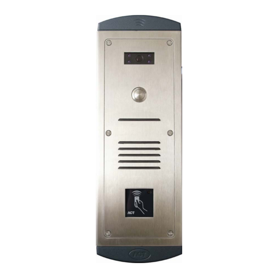
- Page 8 ACTentry V-IP Operating and Installation Manual 2.0 Surface mount Surface Mount Box Front Panel • The surface mount box (shown above) should be mounted on a flat surface, taking care to mount it at a height where the camera lens will match eye level.
-
Page 9: Installing The Actentry V-Ip Unit
Ethernet network connection point in close proximity to the unit. 2. The ACTentry V-IP Unit is to be installed no more than 100 metres from the door panel. 3. A 12Volt DC, 1 Amp power supply is to be used to power the ACTentry V- IP Unit and the ACTentry V-IP door panel audio and video modules. -
Page 10: Act Handset And Pc Speaker Connection
ACTentry V-IP Operating and Installation Manual 2.5 ACT handset and PC speaker connection 1. The ACT Handset and PC speakers should be connected according to the diagram above. 2. The PC speakers should be powered and switched on. 3. The PC speakers jack plug (green) should be plugged into the ACT handset jack socket (green). -
Page 11: Act Handset Mounting
ACTentry V-IP Operating and Installation Manual 2.6 ACT handset mounting A handset holder is provided with the ACT handset. This should be mounted in a location that is both easily accessible for the user but not obstructive for the user (as shown below). -
Page 12: Actentry V-Ip Software Installation
The V-IP unit needs to be powered up and connected to the network before proceeding with the installation. ACTentry V-IP software is designed to operate on a PC connected to a TCP/IP network. The ACTentry V-IP software should be installed on any PC where the user is expected to answer calls from the door and allow access to the building To install ACTentry V-IP, insert the CD into your computers CD drive. - Page 13 ACTentry V-IP Operating and Installation Manual A list of available V-IP units will be displayed. Choose the one to be connected to and press Connect. An icon representing the V-IP unit will appear at the bottom of the screen. Click on the icon to get live audio and video from the unit.
-
Page 14: Configure Settings
ACTentry V-IP Operating and Installation Manual 2.10 Configure Settings Click the button on the right hand side to configure the settings for the V-IP unit. Click on Settings to view the settings dialog. Time Delays Door Open: This option specifies the length of time the Door Lock remains open before is closes and locks the door again. - Page 15 Initialisation Settings Restore last connection on start: With this option set, the application will automatically connect to the last ACTentry V-IP units that it was connected to when the PC was shutdown. This should be set. Run automatically on system start-up: With this option set the application is run every time the PC is started-up.
-
Page 16: Setting Video And Audio Properties
ACTentry V-IP Operating and Installation Manual 2.12 Setting Video and Audio properties Click on the V-IP icon to go live. To help configure the video and audio properties, a second person is required at the door panel. Check that the person at the door panel can be heard from the PC speakers or the PC handset. - Page 17 PC user, adjust the PC Microphone sensitivity, from the Audio Settings tab. A boost to the sensitivity may also be applied. Ready for use The ACTentry V-IP system is now ready for use. The application will now run in the background monitoring the door. Page 15 Issue 3...
-
Page 18: Operation
Click Answer Call icon and the image will pop up on screen.The ACT handset should be lifted and used to converse with the person at the door and access may or may not be granted accordingly with the Grant or Deny Access buttons. -
Page 19: Troubleshooting
If feedback persists check the wiring between the ACTentry V-IP unit and the ACTentry V-IP door panel. Audio Out and MIC In should be wired to T and R respectively of the Audio unit panel on a twisted pair. - Page 20 ACTentry V-IP Operating and Installation Manual Difficult to hear the person at the door Increase Speaker volume setting. The person at the door cannot hear PC User Ensure that Sound recording is set to the Microphone input (NOT Line In). This can be found in Control Panel->...
- Page 21 • Check the Tamper spring on the ACTentry V-IP unit is fitted and not impeded by wiring. • Ensure the Door Contact (DC) input on the ACTentry V-IP unit is linked to • Power down and power up the ACTentry V-IP unit again.
-
Page 22: Setting Fixed Ip Address
1. Type cmd 2. telnet <IP ADDRESS> eg. telnet 172.27.72.85 3. When prompted for the password, enter ACT 4. Type ? to get a list of commands 5. To set the ip address enter: setip <ip address> <gateway> <subnetmask>... - Page 23 ACTentry V-IP Operating and Installation Manual If the V-IP unit does not have a known IP address, then it can be set to a default value by doing the following: 1. Power up the unit 2. Remove Link J307 on the top right hand side of board.
-
Page 24: Installing Actentry V-Ip Unit And Actentry V-Ip Door Panel
ACTentry V-IP Installation +12V AUDIO VIDEO Issue 3... -
Page 25: Actpro-X 1030 Panel Mount Reader Installation
The standard wiring colours for ACTentry V-IP Panel Mount Proximity reader is shown above. Rear view of ACTentry V-IP Panel Mount Reader Readers should be a maximum of 30m from the controller when powered from LED Control... -
Page 26: Actentry V-Ip Waterproofing
ACTentry V-IP Waterproofing Installation Notice: ACTentry V-IP (flush mount) After the installation of a flush mounted ACTentry V-IP unit is complete, it is important to seal the gap between the mounting plate and the wall surface using an appropriate watertight sealing compound.
Need help?
Do you have a question about the ACTENTRY V-IP and is the answer not in the manual?
Questions and answers