ACT ACTentry V-IP Operating And Installtion Instructions
Hide thumbs
Also See for ACTentry V-IP:
- Datasheet (2 pages) ,
- Operating and installation instructions (26 pages)
Table of Contents
Advertisement
Quick Links
Advertisement
Table of Contents

Related Manuals for ACT ACTentry V-IP


Summary of Contents for ACT ACTentry V-IP
- Page 1 ACTentry V-IP Operating & Installation Instructions 18-00082 Rev 3.1 Issue 1...
- Page 2 Access Control Technology Ltd. reserve the right to change the contents of this manual and the system it applies to without prior notice. While every effort has been taken by ACT to ensure the accuracy of the information contained within this document, ACT assumes no responsibility for any errors or omissions.
-
Page 3: Table Of Contents
OPERATION .................... 17 TROUBLESHOOTING ................18 SETTING A FIXED IP ADDRESS ............22 ACTentry V-IP panel Mount Installation Diagram ........24 Installation Notice for Flush mount units........... 25 Mounting instructions for Extended Version of ACTentry V-IP....26 Page 2... -
Page 4: Ordering Information
ACTentry V-IP Operating and Installation Manual Ordering Information ACT Product Code Product description ACTentry V-IP SK Surface Mount Kit* ACTentry V-IP FK Flush Mount Kit* ACTentry V-IP SP VoIP Door Entry Panel (surface ) ACTentry V-IP FP VoIP Door Entry Panel (flush ) -
Page 5: Introduction
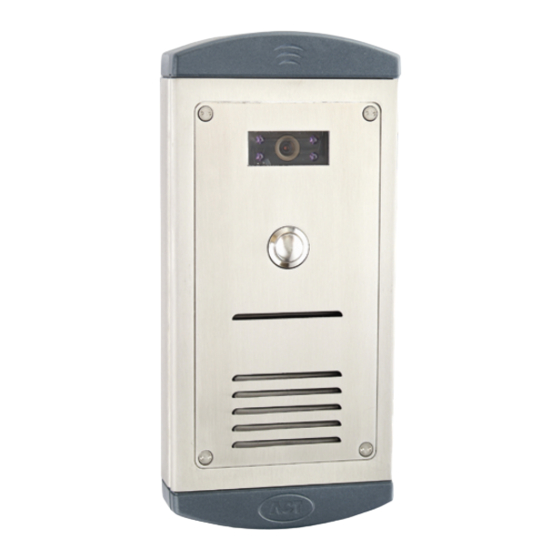
1. ACTentry V-IP Door Panel: The door panel has a Call button, colour video camera and audio unit. Note: The extended versions of the entry panel has a cut out for an ACT 1030 panel mount proximity reader. 2. ACTentry V-IP Controller: The controller has an Ethernet interface and converts video and audio signals from Door Panel to TCP/IP data. -
Page 6: Installation
ACTentry V-IP Operating and Installation Manual 2.0 INSTALLATION 2.1 System Requirements The minimum PC requirements are: 1. Colour SVGA monitor with at least 800x600 screen resolution 2. Mouse and keyboard 3. CDROM drive (required during installation only) 4. Ethernet or FastEthernet LAN connection with TCP/IP protocol (100MBps preferable) 5. -
Page 7: Installing Actentry V-Ip Door Panel
ACTentry V-IP Operating and Installation Manual 2.2 Installing ACTentry V-IP door panel Page 6... - Page 8 ACTentry V-IP Operating and Installation Manual The ACTentry V-IP door panel is available in Flush-mount or Surface-Mount versions. 1. Flush-mount Flush mount Back Box Page 7...
- Page 9 ACTentry V-IP Operating and Installation Manual The flush-mount version comprises of two parts: 1. Flush mount back box 2. Flush mount plate The flush mount back box (previous page) should be sunk into the mounting surface. Ensure to mount it at a height where the camera lens will match eye level.
- Page 10 ACTentry V-IP Operating and Installation Manual 2. Surface mount Surface Mount Box Front Panel The surface mount box (shown above) should be mounted on a flat surface, taking care to mount it at a height where the camera lens will match eye level.
-
Page 11: Installing The Actentry V-Ip Unit
Door Contact (DC) input monitors the door state (open or closed). Alarm Relay The ACTentry V-IP unit also comes with a built in alarm relay. The alarm relay switches while either the following conditions are in place: 1. Tamper open i.e. lid of ACTentry V-IP box open. -
Page 12: Act Handset And Pc Speaker Connection
(about once per second), the ACTentry V-IP controller unit is powered but not connected to the network. 2. When the red LINK LED is on, the ACTentry V-IP is successfully connected to the network. 3. The green TX/RX LED beside the LAN indicates data transmission between the network and the device. -
Page 13: Actentry V-Ip Software Installation
ACTentry V-IP software is designed to operate on a PC connected to a TCP/IP Local Area Network. The ACTentry V-IP software should be installed on any PC where the user is expected to answer calls from the door and allow access to the building. - Page 14 ACTentry V-IP Operating and Installation Manual A list of available ACTentry V-IP units on the network (LAN) will be displayed. e. “Tick” the units to be monitored by the ACTentry V-IP software. f. Click the “Apply” button to save changes.
-
Page 15: Configure Settings
ACTentry V-IP Operating and Installation Manual 2.9 Configure Settings a. Click Setup button to configure the settings for the selected V-IP unit. Page 14... - Page 16 ACTentry V-IP Operating and Installation Manual Door Name: This is the name that will appear on the application and in reports. By default it is the IP address of the V-IP. A more user friendly name (e.g. Front Door) may be entered here.
- Page 17 ACTentry V-IP Operating and Installation Manual b. Click on Audio Tab to configure the Audio settings in the PC. To help configure the audio properties, a second person is required at the door V-IP panel. Check that the person at the door can be heard from the PC speakers or the PC handset.
-
Page 18: Operation
ACTentry V-IP Operating and Installation Manual 3.0 OPERATION When the call button at the ACTentry V-IP entry panel is pressed, the ACTentry software will immediately pop-up a notification at the bottom right of the monitor. When the “Pop-Up Delay” is longer than 0 seconds the ACTentry V-IP software will wait for the delay time before popping up the notification unless the call is answered by another operator. -
Page 19: Troubleshooting
ACTentry V-IP Operating and Installation Manual 4.0 TROUBLESHOOTING No V-IPs found on the network Check that all V-IP units are powered up and connected to the Local Area Network. On the V-IP unit, check the red LINK LED is on. - Page 20 ACTentry V-IP Operating and Installation Manual Audio Feedback is heard by PC user when connected to live video Lift the ACT Handset and listen. Go to the Audio Settings and decrease the microphone sensitivity and speaker volumes. The feedback should now be gone.
- Page 21 ACTentry V-IP Operating and Installation Manual The person at the door cannot hear PC User Increase the Microphone sensitivity in Audio Settings. Also check the following: 1. Ensure that the Speaker Grill is fitted securely against the Door Entry Panel Grill.
- Page 22 The “Allow Access” option does not open the door Check the wiring between the Lock Relay terminals on the ACTentry V- IP unit and the lock Use a multi-meter to check that the Lock Relay on the ACTentry V-IP is switching over. Alarm is constantly on ...
-
Page 23: Setting A Fixed Ip Address
1. Type cmd, to run the DOS command window. 2. telnet IP ADDRESS of V-IP Unit e.g. telnet 172.27.72.85 3. When prompted for the password, enter ACT 4. Type ? to get a list of commands 5. To set the ip address enter: setip ip address gateway subnetmask Eg. - Page 24 ACTentry V-IP Operating and Installation Manual If the V-IP unit does not have a known IP address, then it can be set to a default value by doing the following: 1. Power up the unit 2. Remove Link J9 (near the CALL connection on the board) 3.
-
Page 25: Actentry V-Ip Panel Mount Installation Diagram
ACTentry V-IP Operating and Installation Manual 6.0 ACTentry V-IP panel Mount Installation Diagram Page 24... -
Page 26: Installation Notice For Flush Mount Units
ACTentry V-IP Operating and Installation Manual 7.0 Installation Notice for Flush mount units. Page 25... -
Page 27: Mounting Instructions For Extended Version Of Actentry V-Ip
8.0 Mounting instructions for Extended Version of ACTentry V-IP. The ACTentry V-IP door panel is available in Flush-mount or Surface-Mount versions with a cut out for panel mount readers. ACTentry V-IP FPX - Flush-mount panel with cut out for panel... - Page 28 ACTentry V-IP Operating and Installation Manual The flush-mount version comprises of two parts: 1. Flush mount back box 2. Flush mount plate The flush mount back box (shown above) should be sunk into the mounting surface. Ensure to mount it at a height where the camera lens will match eye level.
- Page 29 ACTentry V-IP Operating and Installation Manual ACTentry V-IP SPX – Surface mount panel with cut out for panel mount reader Surface Mount Box Front Panel The surface mount box (shown above) should be mounted on a flat surface, taking care to mount it at a height where the camera lens will match eye level.
- Page 30 ACTentry V-IP Operating and Installation Manual Ordering Information: ACT Product Code Product description ACTentry V-IP SK Surface Mount Kit* ACTentry V-IP FK Flush Mount Kit* ACTentry V-IP SP VoIP Door Entry Panel (surface ) ACTentry V-IP FP VoIP Door Entry Panel (flush )
Need help?
Do you have a question about the ACTentry V-IP and is the answer not in the manual?
Questions and answers