Compaq ProLiant 8000 Maintenance And Service Manual
Proliant 8000 intel pentium iii xeon 700mhz servers
Hide thumbs
Also See for ProLiant 8000:
- Technology brief (23 pages) ,
- White paper (18 pages) ,
- Features manual (11 pages)

Subscribe to Our Youtube Channel
Related Manuals for Compaq ProLiant 8000

Summary of Contents for Compaq ProLiant 8000
- Page 1 ProLiant 8000 Intel Pentium III Xeon 700MHz Servers Maintenance and Service Guide First Edition (April 2000) Part Number 187242-001 Spare Part Number 192848-001 Compaq Computer Corporation...
- Page 2 PROFITS, BUSINESS INTERRUPTION OR LOSS OF BUSINESS INFORMATION), EVEN IF COMPAQ HAS BEEN ADVISED OF THE POSSIBILITY OF SUCH DAMAGES. The limited warranties for Compaq products are exclusively set forth in the documentation accompanying such products. Nothing herein should be construed as constituting a further or additional warranty.
-
Page 3: Table Of Contents
Contents About This Guide Symbols in Text......................vii Compaq Technician Notes ..................viii Where to Go for Additional Help ................viii Integrated Management Display................ix Telephone Numbers .................... ix Chapter 1 Illustrated Parts Catalog Mechanical Parts Exploded View................1-2 Mechanical Spare Parts List ..................1-3 System Components Exploded View ...............1-5... - Page 4 Compaq ProLiant 8000 Intel Pentium III Xeon 700MHz Servers Maintenance and Service Guide Removal and Replacement Procedures continued Drive Cage with Backplane Board .................2-21 Power On/Standby Switch..................2-22 Power Supply Lock Bar..................2-24 Power Supplies .......................2-25 Power Supply Blanking Panel .................2-26 Hot-Plug Power Supplies ................2-27...
- Page 5 1100 – 1199, Serial Test Error Codes .............3-40 1200 – 1299, Modem Communications Test Error Codes ......3-40 6000 – 6099, Compaq NIC Boards Test Error Codes ........3-41 6500 – 6599, SCSI Hard Drive Test Error Codes ...........3-41 6600 – 6699, SCSI/IDE CD-ROM Drive Test Error Codes......3-42 6700 –...
- Page 6 Compaq ProLiant 8000 Intel Pentium III Xeon 700MHz Servers Maintenance and Service Guide Connectors, Switches, and Status Indicators continued Status Indicators .......................4-7 Front Panel System Interlock LED Status Indicators ........4-7 I/O Board System Power Interlock LED Indicators ..........4-8 Processor Board LED Status Indicators ............4-10 Hot-Plug I/O Fan LED Status Indicators............4-11...
-
Page 7: About This Guide
About This Guide This maintenance and service guide can be used for reference when servicing Compaq ä ProLiant 8000 servers. WARNING: To reduce the risk of personal injury from electric shock and hazardous energy levels, only authorized service technicians should attempt to repair this equipment. Improper repairs could create conditions that are hazardous. -
Page 8: Compaq Technician Notes
Compaq ProLiant 8000 Intel Pentium III Xeon 700MHz Servers Maintenance and Service Guide Compaq Technician Notes Any product or assembly marked with these symbols indicates that the component exceeds the recommended weight for one individual to handle safely. Weight in kg... -
Page 9: Integrated Management Display
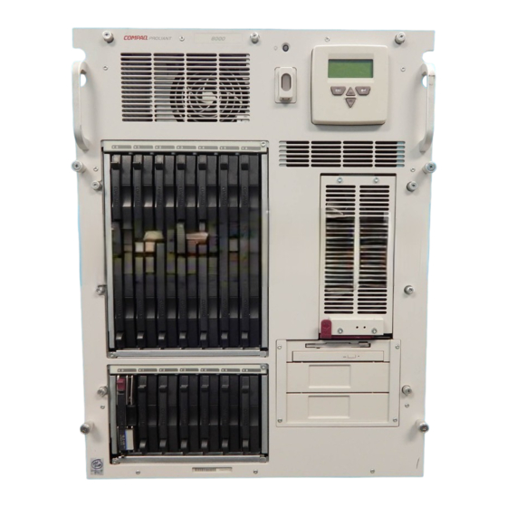
About This Guide ix Integrated Management Display All Compaq ProLiant 8000 servers include a Compaq Integrated Management Display (IMD), which is an integrated, 16 x 4 character display mounted on the front of the server. This display provides easy-to-use, menu-driven access to server information, including model number, LCD firmware revision, and POST operations. -
Page 10: Illustrated Parts Catalog
Illustrated Parts Catalog This chapter provides the illustrated parts breakdown and a spare parts list for the ProLiant 8000 server. Table 1-1 contains mechanical part descriptions and spare part numbers. Table 1-2 contains system component descriptions and spare part numbers... -
Page 11: Mechanical Parts Exploded View
1-2 Compaq ProLiant 8000 Intel Pentium III Xeon 700MHz Servers Maintenance and Service Guide Mechanical Parts Exploded View Figure 1-1. Mechanical parts exploded view... -
Page 12: Mechanical Spare Parts List
Illustrated Parts Catalog 1-3 Mechanical Spare Parts List Table 1-1 Mechanical Spare Parts List Item Description Spare Part Number Chassis Chassis 126978-001 Upper and lower processor guides 126972-001 a) Upper processor support structure b) Lower processor support structure Top access panel with access key 126979-001 Right side access panel 126991-001... - Page 13 1-4 Compaq ProLiant 8000 Intel Pentium III Xeon 700MHz Servers Maintenance and Service Guide Table 1-1 Mechanical Spare Parts List continued Item Description Spare Part Number Miscellaneous hardware kit 126984-001 a) Memory board retention bracket* b) Expansion board blanking panel*...
-
Page 14: System Components Exploded View
Illustrated Parts Catalog 1-5 System Components Exploded View Figure 1-2. System components exploded view... -
Page 15: System Components Spare Parts List
1-6 Compaq ProLiant 8000 Intel Pentium III Xeon 700MHz Servers Maintenance and Service Guide System Components Spare Parts List Table 1-2 System Components Spare Parts List Item Description Spare Part Number Assemblies Hot-plug rear processor fans 126987-001 Redundant rear processor fans... - Page 16 Illustrated Parts Catalog 1-7 Table 1-2 System Components Spare Parts List continued Item Description Spare Part Number Miscellaneous screw kit* 154954-001 a) Screw, taptite, T-15, oval-head b) Screw, 6-32x.312 inch, TF, HI/TP c) Screw, shoulder, 6-32x.335 inch, Torx-15 d) Screw/washer Miscellaneous power cable kit* 126986-001 a) 10-position, 6A, 6-inch power cable...
- Page 17 1-8 Compaq ProLiant 8000 Intel Pentium III Xeon 700MHz Servers Maintenance and Service Guide Table 1-2 System Components Spare Parts List continued Item Description Spare Part Number Illustrated parts map* 192847-001 Options Keyboard* 160648-XXX Ethernet loopback RJ-45* 317465-001 4.3-GB 1-inch 10,000 rpm Ultra2 hard drive with tray* 336380-001 9.1-GB 1-inch 7,200 rpm Ultra2 hard drive with tray*...
-
Page 18: Removal And Replacement Procedures
Removal and Replacement Procedures This chapter provides subassembly/module-level removal and replacement procedures for Compaq ProLiant 8000 servers. After completing all necessary removal and replacement procedures, run the Diagnostics program to verify that all components operate properly. To service Compaq ProLiant 8000 servers, you might need the following:... -
Page 19: Symbols In Equipment
2-2 Compaq ProLiant 8000 Intel Pentium III Xeon 700MHz Servers Maintenance and Service Guide Symbols in Equipment WARNING: Any surface or area of the equipment marked with these symbols indicates the presence of a hot surface or hot component. If this surface is contacted, the potential for injury exists. To reduce the risk of injury from a hot component, allow the surface to cool before touching it. -
Page 20: System Interlocks
Removal and Replacement Procedures 2-3 System Interlocks Compaq ProLiant 8000 servers ship with system interlocks. System interlocks consist of three LEDs providing a closed-loop checking mechanism for verifying proper cabling interconnects between critical server components. These LEDs are located on both the I/O and the processor boards. -
Page 21: Turning Off The Server
3. Disconnect all power cords from the server. 4. For some removal and replacement procedures, you must remove the server from the rack and place it on a sturdy table or workbench. Refer to the Compaq ProLiant 8000 Setup and Installation Guide for instructions. -
Page 22: Rack Warnings
If the system has multiple power supplies, disconnect power from the system by unplugging all power cords from the power supplies. CAUTION: Compaq ProLiant 8000 servers must always be operated with the system unit cover on. Proper cooling will not be achieved if the system unit cover is removed. -
Page 23: Top Access Panel
2-6 Compaq ProLiant 8000 Intel Pentium III Xeon 700MHz Servers Maintenance and Service Guide Top Access Panel WARNING: To reduce the risk of personal injury from hot surfaces, allow the internal system components to cool before touching them. CAUTION: When the server is powered up, the access panel must be installed for proper system cooling. -
Page 24: Right Side Access Panel
Removal and Replacement Procedures 2-7 Right Side Access Panel WARNING: To reduce the risk of personal injury from hot surfaces, allow the internal system components to cool before touching them. CAUTION: When the server is powered on, the access panels must be installed for proper system cooling. -
Page 25: Left Side Access Panel
2-8 Compaq ProLiant 8000 Intel Pentium III Xeon 700MHz Servers Maintenance and Service Guide Left Side Access Panel WARNING: To reduce the risk of personal injury from hot surfaces, allow the internal system components to cool before touching them. CAUTION: When the server is powered on, the access panels must be installed for proper system cooling. -
Page 26: Casters
Removal and Replacement Procedures 2-9 Casters To remove the casters: 1. Perform the preparation procedures. See “Preparation Procedures” earlier in this chapter. 2. Place the server on its side. 3. Remove the three T-15 screws securing each caster to the bottom of the server. 4. -
Page 27: Front Air Baffle
2-10 Compaq ProLiant 8000 Intel Pentium III Xeon 700MHz Servers Maintenance and Service Guide Front Air Baffle To remove the front air baffle: 1. Perform the preparation procedures. See “Preparation Procedures” earlier in this chapter. 2. Remove the right side access panel. See “Right Side Access Panel” earlier in this chapter. -
Page 28: Rear Air Baffle
Removal and Replacement Procedures 2-11 Rear Air Baffle To remove the rear air baffle: 1. Perform the preparation procedures. See “Preparation Procedures” earlier in this chapter. 2. Remove the right side access panel. See “Right Side Access Panel” earlier in this chapter. 3. -
Page 29: Main Processor Air Baffle
2-12 Compaq ProLiant 8000 Intel Pentium III Xeon 700MHz Servers Maintenance and Service Guide Main Processor Air Baffle To remove the main processor air baffle: 1. Perform the preparation procedures. See “Preparation Procedures” earlier in this chapter. 2. Remove the right side access panel. See “Right Side Access Panel” earlier in this chapter. -
Page 30: Face Plates
Removal and Replacement Procedures 2-13 Face Plates NOTE: The front bezel and the removable media trim can be removed independently of each other. Removable Media Trim To remove the removable media trim: 1. Remove the four T-15 screws securing the removable media trim to the front of the chassis. -
Page 31: Front Bezel
2-14 Compaq ProLiant 8000 Intel Pentium III Xeon 700MHz Servers Maintenance and Service Guide Front Bezel To remove the front bezel: 1. Remove the twelve T-15 screws securing the front bezel to the chassis. 2. Pull the front bezel away from the server. -
Page 32: Mass Storage And Removable Media Devices
Removal and Replacement Procedures 2-15 Mass Storage and Removable Media Devices Mass storage in Compaq ProLiant 8000 servers is divided between three hot-plug hard drive cages and a removable media area. Mass storage and removable media devices include the following: Up to seven 1-inch form factor Ultra2 hard drives (SCSI IDs 0 to 5, and 8) per drive cage One slim-line combination CD-ROM/1.44-MB diskette drive... -
Page 33: Removable Media Blanking Panel
2-16 Compaq ProLiant 8000 Intel Pentium III Xeon 700MHz Servers Maintenance and Service Guide Removable Media Blanking Panel To remove a removable media blanking panel from the removable media area: 1. Remove the removable media trim. See “Removable Media Trim” earlier in this chapter. -
Page 34: Removable Media Devices
Removal and Replacement Procedures 2-17 Removable Media Devices To remove a removable media device from the removable media area: 1. Perform the preparation procedures. See “Preparation Procedures” earlier in this chapter. 2. Remove the right side access panel. See “Right Side Access Panel” earlier in this chapter. 3. -
Page 35: Hard Drive Blanking Panels
2-18 Compaq ProLiant 8000 Intel Pentium III Xeon 700MHz Servers Maintenance and Service Guide Hard Drive Blanking Panels To remove a hard drive blanking panel from a hard drive bay: 1. Press the lower release button 2. Pull the hard drive blanking panel away from the server Figure 2-13. -
Page 36: Hot-Plug Drive Replacement Guidelines
Hot-Plug Drive Replacement Precautions Be aware of the following Compaq guidelines for safe hot-plug replacement: Do not remove a degraded drive if any other member of the array is offline (the online LED is off). - Page 37 2-20 Compaq ProLiant 8000 Intel Pentium III Xeon 700MHz Servers Maintenance and Service Guide CAUTION: Do not turn off an attached disk drive enclosure when the server containing the Smart Array Controller is powered on. Also, do not turn on the server before turning on the disk enclosure.
-
Page 38: Drive Cage With Backplane Board
Removal and Replacement Procedures 2-21 Drive Cage with Backplane Board To remove a drive cage with backplane board: 1. Perform the preparation procedures. See “Preparation Procedures” earlier in this chapter. 2. Remove the left side access panel. See “Left Side Access Panel” earlier in this chapter. 3. -
Page 39: Power On/Standby Switch
2-22 Compaq ProLiant 8000 Intel Pentium III Xeon 700MHz Servers Maintenance and Service Guide Power On/Standby Switch To remove the Power On/Standby switch: 1. Perform the preparation procedures. See “Preparation Procedures” earlier in this chapter. 2. Remove the top access panel. See “Top Access Panel” earlier in this chapter. - Page 40 Removal and Replacement Procedures 2-23 5. If the plastic switch cover is installed, remove it by prying outward on the upper or lower catch with a 4-mm flatblade screwdriver. Then pull the cover off the switch Figure 2-17. Removing the plastic switch cover 6.
-
Page 41: Power Supply Lock Bar
2-24 Compaq ProLiant 8000 Intel Pentium III Xeon 700MHz Servers Maintenance and Service Guide Power Supply Lock Bar To remove the power supply lock bar: 1. Unlock the padlock securing the top end of the lock bar 2. Pull the top of the lock bar from its secured position . -
Page 42: Power Supplies
3 to 11 Note: Compaq recommends that 220 VAC power is used for all deployments. This will ensure that the server can support its maximum configurations and remain in a redundant power supply state. This table does not imply that a given power supply configuration can support the maximum number of processors, hard drives, memory, and PCI expansion boards listed. -
Page 43: Power Supply Blanking Panel
2-26 Compaq ProLiant 8000 Intel Pentium III Xeon 700MHz Servers Maintenance and Service Guide Power Supply Blanking Panel To remove a power supply blanking panel: 1. If installed, remove the power supply lock bar. See “Power Supply Lock Bar” earlier in this chapter. -
Page 44: Hot-Plug Power Supplies
Removal and Replacement Procedures 2-27 Hot-Plug Power Supplies To remove a hot-plug power supply: 1. In a redundant power supply configuration, it is unnecessary to turn off the power for a hot-plug power supply replacement. For a non-redundant configuration, perform the preparation procedures. - Page 45 2-28 Compaq ProLiant 8000 Intel Pentium III Xeon 700MHz Servers Maintenance and Service Guide 4. Press the center release lever of the power supply handle , then pull the handle downward to detach the power supply from the power backplane board 5.
-
Page 46: Power Backplane Board
Removal and Replacement Procedures 2-29 Power Backplane Board To remove the power backplane board: 1. Perform the preparation procedures. See “Preparation Procedures” earlier in this chapter. 2. Remove the left side access panel. See “Left Side Access Panel” earlier in this chapter. 3. -
Page 47: Fans
2-30 Compaq ProLiant 8000 Intel Pentium III Xeon 700MHz Servers Maintenance and Service Guide Fans ProLiant 8000 servers ship with 10 cooling fans. There are four fan assemblies at the processor area, two at the front and two at the rear of the server. An I/O fan assembly is located at the top of the server. -
Page 48: Redundant Rear Processor Fan
Removal and Replacement Procedures 2-31 Redundant Rear Processor Fan To remove the redundant rear processor fan: 1. Perform the preparation procedures. See “Preparation Procedures” earlier in this chapter. 2. Remove the hot-plug rear processor fan to gain access to the redundant rear processor fan retaining screws. -
Page 49: Hot-Plug Front Processor Fan Assembly
2-32 Compaq ProLiant 8000 Intel Pentium III Xeon 700MHz Servers Maintenance and Service Guide Hot-Plug Front Processor Fan Assembly To remove the hot-plug front processor fan assembly: 1. Pull the lower fan ejector lever out to release the hot-plug front processor fan assembly. -
Page 50: Redundant Front Processor Fan Assembly
Removal and Replacement Procedures 2-33 Redundant Front Processor Fan Assembly To remove the redundant front processor fan assembly: 1. Perform the preparation procedures. See “Preparation Procedures” earlier in this chapter. 2. Remove the hot-plug front processor fan assembly. See “Hot-Plug Front Processor Fan Assembly”... -
Page 51: Hot-Plug Front I/O Fans
2-34 Compaq ProLiant 8000 Intel Pentium III Xeon 700MHz Servers Maintenance and Service Guide Hot-Plug Front I/O Fans The two hot-plug front I/O fans are housed together in a cage assembly, but they can be removed individually. CAUTION: Never remove both hot-plug I/O fans while the server is powered up. Overheating and damage to hardware could result. - Page 52 Removal and Replacement Procedures 2-35 To replace a hot-plug front I/O fan: 1. Hook one finger through the thumbstrap and push the locking latch toward the thumbstrap. 2. Securely seat the hot-plug front I/O fan into the I/O fan cage NOTE: An audible click should occur when the fan is fully seated.
-
Page 53: Hot-Plug I/O Fan Board
2-36 Compaq ProLiant 8000 Intel Pentium III Xeon 700MHz Servers Maintenance and Service Guide Hot-Plug I/O Fan Board To remove the hot-plug I/O fan board: 1. Remove the top access panel. See “Top Access Panel” earlier in this chapter. 2. Remove the hot-plug front I/O fans. See “Hot-Plug Front I/O Fans” earlier in this chapter. -
Page 54: Sdram Memory
2 x 1 GB IMPORTANT: Compaq recommends using only Compaq DIMMs. DIMMs from other sources can adversely affect data integrity. Refer to the Compaq ProLiant 8000 Setup and Installation Guide for information on achieving optimum performance of the memory system. -
Page 55: Memory Expansion Board
IMPORTANT: Memory must be installed in identical pairs. Ensure all modules in a logical bank of two have the same 9-digit Compaq part number. Populate bank 1 (slots 1 and 2) first. Continue populating the memory banks in sequential order. Populate bank 8 last. If the memory is not matched as stated,... - Page 56 Removal and Replacement Procedures 2-39 To remove the memory expansion board: 1. Perform the preparation procedures. See “Preparation Procedures” earlier in this chapter. 2. Remove the right side access panel. See “Right Side Access Panel” earlier in this chapter. 3. Remove the memory expansion board retention bracket by loosening the thumbscrew swinging the left side of the bracket out of the slot , and then pulling the bracket to the left and out the side of the unit...
- Page 57 2-40 Compaq ProLiant 8000 Intel Pentium III Xeon 700MHz Servers Maintenance and Service Guide 4. Rotate the ejector levers outward on each side of the memory expansion board. Then slide the board out of the server Figure 2-34. Removing the memory expansion board Reverse steps 1 through 4 to replace the memory expansion board.
- Page 58 Removal and Replacement Procedures 2-41 To remove a DIMM: 1. Perform the preparation procedures. See “Preparation Procedures” earlier in this chapter. 2. Remove the memory expansion board containing the DIMM modules. See “Memory Expansion Board” earlier in this chapter. 3. Support the underside of the memory expansion board. CAUTION: The ejectors prevent the memory expansion board from lying completely flat.
-
Page 59: Cache Accelerators
2-42 Compaq ProLiant 8000 Intel Pentium III Xeon 700MHz Servers Maintenance and Service Guide Cache Accelerators Cache accelerators are found where more than one processor bus is used. Figure 2-36 shows the location of cache accelerators Figure 2-36. Cache accelerators CAUTION: Cache accelerators are susceptible to damage from electrostatic discharge. - Page 60 Removal and Replacement Procedures 2-43 To remove a cache accelerator: 1. Perform the preparation procedures. See “Preparation Procedures” earlier in this chapter. 2. Remove the right side access panel. See “Right Side Access Panel” earlier in this chapter. 3. Remove the main processor air baffle. See “Main Processor Air Baffle” earlier in this chapter.
- Page 61 2-44 Compaq ProLiant 8000 Intel Pentium III Xeon 700MHz Servers Maintenance and Service Guide 5. Open the lower ejector tab securing the cache accelerator 6. Remove the accelerator from the socket Figure 2-38. Removing a cache accelerator Reverse steps 1 through 6 to replace a cache accelerator.
-
Page 62: Processors, Processor Power Modules, Processor Terminator Boards, Processor Board With Tray
Removal and Replacement Procedures 2-45 Processors, Processor Power Modules, Processor Terminator Boards, Processor Board with Tray The processor board with tray seats up to eight processors and eight Processor Power Modules. CAUTION: Terminator boards must be installed in each unoccupied processor slot to complete the system interlock feature. -
Page 63: Processor
2-46 Compaq ProLiant 8000 Intel Pentium III Xeon 700MHz Servers Maintenance and Service Guide Processor Each processor bus in ProLiant 8000 servers supports four processors. Figure 2-40 illustrates how the processors are properly removed using the ejectors. Figure 2-40. Unlocking and ejecting the processor To remove a processor: 1. - Page 64 Figure 2-41. Removing a processor When installing new processors, follow these guidelines: Use Intel Pentium III Xeon processors. ProLiant 8000 servers do not support Pentium II Xeon processors. ProLiant 8000 servers will not boot if Intel Pentium III Xeon 500/550-MHz processors and Pentium III Xeon 700-MHz or higher speed processors are installed in the same server.
- Page 65 The default setting for the bus/core ratio switches has all switches in the Off position. Compaq recommends that the bus/core ratio switches remain on the default setting to allow the system ROM to detect the correct speed automatically.
- Page 66 Removal and Replacement Procedures 2-49 To install a processor: CAUTION: When installing processors, be sure to install the Processor Power Module first to ensure proper processor operation. 1. Gently guide the processor into the processor slot. IMPORTANT: If the processor is not properly seated, the system interlock prevents the system from powering up.
-
Page 67: Processor Power Modules
2-50 Compaq ProLiant 8000 Intel Pentium III Xeon 700MHz Servers Maintenance and Service Guide Processor Power Modules The Processor Power Modules (which are also called VRMs) of Compaq ProLiant 8000 servers have built-in redundancy to prevent the system from powering down if a Processor Power Module fails. - Page 68 Removal and Replacement Procedures 2-51 To remove a Processor Power Module: 1. Perform the preparation procedures. See “Preparation Procedures” earlier in this chapter. 2. Remove the right side access panel. See “Right Side Access Panel” earlier in this chapter. 3. Remove the main processor air baffle. See “Main Processor Air Baffle” earlier in this chapter.
- Page 69 2-52 Compaq ProLiant 8000 Intel Pentium III Xeon 700MHz Servers Maintenance and Service Guide Processors, Processor Power Modules, Processor Terminator Boards, Processor Board with Tray” section earlier in this chapter. 5. Rotate the side ejector levers on the module outward .
- Page 70 Removal and Replacement Procedures 2-53 To install a Processor Power Module: CAUTION: The redundant Processor Power Module must be installed before the processor. Attempting to install the Processor Power Module after installing the processor could damage the electronic components on the Processor Power Module. 1.
-
Page 71: Processor Terminator Boards
2-54 Compaq ProLiant 8000 Intel Pentium III Xeon 700MHz Servers Maintenance and Service Guide Processor Terminator Boards Processor terminator boards occupy unused processor sockets on the processor board. To remove a processor terminator board: 1. Perform the preparation procedures. See “Preparation Procedures” earlier in this chapter. -
Page 72: Lower Processor Support Structure
Removal and Replacement Procedures 2-55 Lower Processor Support Structure To remove the lower processor support structure: 1. Perform the preparation procedures. See “Preparation Procedures” earlier in this chapter. 2. Remove the right side access panel. See “Right Side Access Panel” earlier in this chapter. 3. - Page 73 2-56 Compaq ProLiant 8000 Intel Pentium III Xeon 700MHz Servers Maintenance and Service Guide Processors, Processor Power Modules, Processor Terminator Boards, Processor Board with Tray” earlier in this chapter. 6. Remove the processor support brace. See “Cache Accelerators” earlier in this chapter.
-
Page 74: Upper Processor Support Structure
Removal and Replacement Procedures 2-57 Upper Processor Support Structure To remove the upper processor support structure: 1. Perform the preparation procedures. See “Preparation Procedures” earlier in this chapter. 2. Remove the lower processor support structure. See “Lower Processor Support Structure” earlier in this chapter. -
Page 75: Processor Board With Tray
2-58 Compaq ProLiant 8000 Intel Pentium III Xeon 700MHz Servers Maintenance and Service Guide Processor Board with Tray To remove the processor board with tray: 1. Perform the preparation procedures. See “Preparation Procedures” earlier in this chapter. 2. Remove the top access panel. See “Top Access Panel” earlier in this chapter. - Page 76 Removal and Replacement Procedures 2-59 Processors, Processor Power Modules, Processor Terminator Boards, Processor Board with Tray” earlier in this chapter. 7. Remove the front and rear air baffles. See “Front Air Baffle” and “Rear Air Baffle” earlier in this chapter. 8.
- Page 77 2-60 Compaq ProLiant 8000 Intel Pentium III Xeon 700MHz Servers Maintenance and Service Guide 11. Loosen the two thumbscrews securing the Processor board Processor Power Module support structure. Then remove the support structure from the processor board. Figure 2-50. Removing the Processor board Processor Power Module support structure 12.
- Page 78 Removal and Replacement Procedures 2-61 15. Loosen the two thumbscrews securing the processor board with tray to the chassis 16. Press the lock lever button with a finger or thumb and pull down the processor board handle 17. Lower the processor board with tray from the back of the chassis .
-
Page 79: Integrated Management Display
2-62 Compaq ProLiant 8000 Intel Pentium III Xeon 700MHz Servers Maintenance and Service Guide Integrated Management Display To remove the Integrated Management Display (IMD): 1. Perform the preparation procedures. See “Preparation Procedures” earlier in this chapter. 2. Remove the top access panel. See “Top Access Panel” earlier in this chapter. -
Page 80: I/O Expansion Slots And Related Components
To access the I/O expansion slots: 1. Insert the access key into the PCI Hot Plug access door and turn it counter-clockwise NOTE: Compaq recommends leaving the PCI Hot Plug access doors locked during normal use. Figure 2-54. Unlocking the PCI Hot Plug access doors WARNING: To reduce the risk of personal injury from hot surfaces, allow the internal system components to cool before touching them. - Page 81 2-64 Compaq ProLiant 8000 Intel Pentium III Xeon 700MHz Servers Maintenance and Service Guide 2. Slide back the locking lever on the PCI Hot Plug access door 3. Open the PCI Hot Plug access doors Figure 2-55. Opening the PCI Hot Plug access doors...
- Page 82 Removal and Replacement Procedures 2-65 Figure 2-56 shows the Compaq ProLiant 8000 I/O expansion board slot positions from the top of the server and; Figure 2-57 shows the slot positions from the back of the server. Table 2-6 shows which devices the slots can support.
- Page 83 2-66 Compaq ProLiant 8000 Intel Pentium III Xeon 700MHz Servers Maintenance and Service Guide Figure 2-57. Rear view of the I/O expansion board slots Table 2-7 I/O Expansion Board Slots Item Description 32-bit/33-MHz PCI Hot Plug (universal or 5-V keying)
-
Page 84: Array Controllers With Extended Scsi
Removal and Replacement Procedures 2-67 Array Controllers with Extended SCSI To remove an array controller with Extended SCSI architecture: 1. Unlock then open the PCI Hot Plug access doors. See “I/O Expansion Slots” earlier in this chapter. 2. Deactivate the expansion board slot LED by pressing the square button on the PCI switchboard CAUTION: Do not open the slot release lever unless the green PCI Hot Plug LED indicator for the slot is off. - Page 85 2-68 Compaq ProLiant 8000 Intel Pentium III Xeon 700MHz Servers Maintenance and Service Guide 5. Pull the ejector levers outward . Then lift the board from the unit Figure 2-59. Removing an array controller with Extended SCSI...
- Page 86 Removal and Replacement Procedures 2-69 To replace an array controller with Extended SCSI: 1. Line up the controller with the appropriate slot 2. Push the controller into the bus slot. NOTE: Seat the controller into the slot using the ejector levers to ensure complete board connection. 3.
-
Page 87: Extended Scsi Dividers
2-70 Compaq ProLiant 8000 Intel Pentium III Xeon 700MHz Servers Maintenance and Service Guide Extended SCSI Dividers Extended SCSI dividers, adjacent to slots 10 and 11, provide leverage for removing and replacing extended SCSI array controllers and add insulation to any PCI board plugged into these slots. -
Page 88: I/O Expansion Boards
For more information refer, to the Compaq ProLiant 8000 Servers Setup and Installation Guide. CAUTION: DO NOT open the slot release lever unless the green PCI Hot Plug LED power indicator for the slot is off. -
Page 89: Cabling Diagrams
2-72 Compaq ProLiant 8000 Intel Pentium III Xeon 700MHz Servers Maintenance and Service Guide Cabling Diagrams Figure 2-63. Connecting the PCI SCSI controller board to removable media bays (typical) - Page 90 Removal and Replacement Procedures 2-73 Cage 3 Cage 2 Cage 1 Figure 2-64. Connecting an array controller with Extended SCSI to drive cage 1, 2, or 3...
-
Page 91: Hot-Plug Basket Insulator
2-74 Compaq ProLiant 8000 Intel Pentium III Xeon 700MHz Servers Maintenance and Service Guide Hot-Plug Basket Insulator To remove the hot-plug basket insulator: 1. Perform the preparation procedures. See “Preparation Procedures” earlier in this chapter. 2. Remove the top access panel. See “Top Access Panel” earlier in this chapter. -
Page 92: Expansion Board Guide
Removal and Replacement Procedures 2-75 Expansion Board Guide To remove the expansion board guide: 1. Perform the preparation procedures. See “Preparation Procedures” earlier in this chapter. 2. Remove the top access panel. See “Top Access Panel” earlier in this chapter. 3. -
Page 93: Pci Hot Plug Interface Board
2-76 Compaq ProLiant 8000 Intel Pentium III Xeon 700MHz Servers Maintenance and Service Guide PCI Hot Plug Interface Board To remove the PCI Hot Plug interface board: 1. Remove the top access panel. See “Top Access Panel” earlier in this chapter. -
Page 94: I/O Board
Removal and Replacement Procedures 2-77 I/O Board To remove the I/O board: 1. Perform the preparation procedures. See “Preparation Procedures” earlier in this chapter. 2. Remove the array controller with Extended SCSI. See “Array Controllers with Extended SCSI” earlier in this chapter. 3. - Page 95 2-78 Compaq ProLiant 8000 Intel Pentium III Xeon 700MHz Servers Maintenance and Service Guide 9. Tilt the board from the back of server to clear the video connector 10. Lift the I/O board through the top of the server Figure 2-69. Clearing the video connector area of the I/O board...
-
Page 96: External Battery
CAUTION: Batteries, battery packs, and accumulators should not be disposed of together with the general household waste. In order to forward them to recycling or proper disposal, use the public collection system or return them to Compaq, your authorized Compaq Partners, or their agents. - Page 97 2-80 Compaq ProLiant 8000 Intel Pentium III Xeon 700MHz Servers Maintenance and Service Guide 7. Place the sticker included with your battery kit on the back of your server above the power connector. IMPORTANT: You must run the Compaq System Configuration Utility to reconfigure the server after...
-
Page 98: Diagnostics And Troubleshooting
Chapter Diagnostics and Troubleshooting This chapter describes software and firmware diagnostic tools available for all Compaq server products. The sections in this chapter are: Diagnostic Tools Utility Overview Default Configuration Utilities Access Power-On Self-Test Diagnostics Software Array Diagnostic Utility Integrated Management Log... -
Page 99: Diagnostic Tools Utility Overview
3-2 Compaq ProLiant 8000 Intel Pentium III Xeon 700MHz Servers Maintenance and Service Guide Diagnostic Tools Utility Overview These utilities were developed to assist in diagnosing problems, testing the hardware, and monitoring and managing Compaq server hardware. Table 3-1 Diagnostic Tools... - Page 100 ADU are to collect all possible information about the array controllers in the system and to generate a list of detected problems. This tool is available for all Compaq servers covered by this guide. Drive Array The predecessor to ADU, DAAD is a...
-
Page 101: Default Configuration
3-4 Compaq ProLiant 8000 Intel Pentium III Xeon 700MHz Servers Maintenance and Service Guide Default Configuration When the system is first turned on, the system ROM detects the unconfigured state of the hardware and provides default configuration settings for most devices. By providing this initialization, the system can run Diagnostics and other software applications before running the normal SmartStart and System Configuration programs. -
Page 102: Utilities Access
Software CD. This will result in data loss to the entire system. Running Compaq Utilities Compaq Utilities can be run from the system partition, from diskette, or from the Compaq SmartStart and Support Software CD. Running the Utilities from the System Partition If the system partition was installed using SmartStart, the Compaq utilities will automatically be available on the system partition. - Page 103 Software CD IMPORTANT: Only the System Configuration Utility, Array Configuration Utility, and Array Diagnostic Utility can be executed from the Compaq SmartStart and Support Software CD. All other utilities must be executed from the system partition or from diskette. To run these utilities directly from the Compaq SmartStart and Support Software CD: 1.
-
Page 104: Power-On Self-Test
If an error code displays on the screen during POST or after resetting the system, use the instructions in the POST Error Messages table. NOTE: Many of the actions listed require you to run Diagnostics or the Compaq System Configuration Utility. Steps for running these utilities are provided following the POST Error Messages tables. - Page 105 3-8 Compaq ProLiant 8000 Intel Pentium III Xeon 700MHz Servers Maintenance and Service Guide Table 3-2 POST Error Messages Error Code Audible Beeps Probable Source of Problem Recommended Action A Correctable None A memory module has Run Compaq Diagnostics to...
- Page 106 System Halted processor and update the system to latest ROM. 101-ROM Error 1 long, 1 short System ROM checksum. Run Compaq Diagnostics. Replace failed assembly as indicated. 101-I/O ROM Error None Options ROM checksum. Run Compaq Diagnostics.
- Page 107 3-10 Compaq ProLiant 8000 Intel Pentium III Xeon 700MHz Servers Maintenance and Service Guide Table 3-2 POST Error Messages continued Error Code Audible Beeps Probable Source of Problem Recommended Action 163-Time & Date Not 2 short Invalid time or date in Run the System Configuration configuration memory.
- Page 108 Module (PPM) installed in supports redundancy. installed for indicated processor slot. Processor X 212-System 1 short Processor in slot x failed. Run Compaq Diagnostics and Processor Failed/ replace failed processor. Mapped out 214-DC-DC None Processor Power Module (PPM) Run Compaq Diagnostics.
- Page 109 3-12 Compaq ProLiant 8000 Intel Pentium III Xeon 700MHz Servers Maintenance and Service Guide Table 3-2 POST Error Messages continued Error Code Audible Beeps Probable Source of Problem Recommended Action 219-Snoop Rules None Catastrophic chipset failure Call Compaq authorized service SRAM Failure.
- Page 110 If you have resolve the resource recently added new conflict. hardware remove it Run Compaq Diagnostics to see if it is the to resolve the issue. cause of the conflict. Alternatively, use Computer Setup or...
- Page 111 3-14 Compaq ProLiant 8000 Intel Pentium III Xeon 700MHz Servers Maintenance and Service Guide Table 3-2 POST Error Messages continued Error Code Audible Beeps Probable Source of Problem Recommended Action 800-Server Feature None The system has detected the Install the Server Feature...
- Page 112 Diagnostics and Troubleshooting 3-15 Table 3-2 POST Error Messages continued Error Code Audible Beeps Probable Source of Problem Recommended Action 803-Processor None Two processors with different Replace one of the speeds must match speed ratings are installed in the processors with a for system operation.
- Page 113 3-16 Compaq ProLiant 8000 Intel Pentium III Xeon 700MHz Servers Maintenance and Service Guide Table 3-2 POST Error Messages continued Error Code Audible Beeps Probable Source of Problem Recommended Action 806-NVRAM has None The system configuration switch Remove power from the...
- Page 114 Diagnostics and Troubleshooting 3-17 Table 3-2 POST Error Messages continued Error Code Audible Beeps Probable Source of Problem Recommended Action 1155-Serial Port 2 short A hardware conflict is preventing Run the System Configuration Address Conflict the normal operation of a serial Utility to reassign the serial port Detected port.
- Page 115 3-18 Compaq ProLiant 8000 Intel Pentium III Xeon 700MHz Servers Maintenance and Service Guide Table 3-2 POST Error Messages continued Error Code Audible Beeps Probable Source of Problem Recommended Action 1613-Low System None Real time clock system battery is Replace battery (or add external Battery running low on power.
- Page 116 SCSI device. Remove SCSI cables from the controller and observe if the failure still occurs. If necessary, replace the cables. Run Compaq Diagnostics. Remove individual SCSI devices from the cable to identify a suspect device. Replace failed assembly. 1702-SCSI cable None SCSI cable has failed.
- Page 117 3-20 Compaq ProLiant 8000 Intel Pentium III Xeon 700MHz Servers Maintenance and Service Guide Table 3-2 POST Error Messages continued Error Code Audible Beeps Probable Source of Problem Recommended Action 1721-Slot X Drive None Monitor and Performance Replace the drive when it is Array –...
- Page 118 Diagnostics and Troubleshooting 3-21 Table 3-2 POST Error Messages continued Error Code Audible Beeps Probable Source of Problem Recommended Action 1727-Slot x Drive None Additional drives detected. This message indicates that the Array – New Logical controller has detected an Drive(s) Attachment additional array of drives that Detected.
- Page 119 3-22 Compaq ProLiant 8000 Intel Pentium III Xeon 700MHz Servers Maintenance and Service Guide Table 3-2 POST Error Messages continued Error Code Audible Beeps Probable Source of Problem Recommended Action 1751-Fixed Disk 1 None Fixed disk drive error detected. Run the System Configuration failed Identify Utility and correct.
- Page 120 Array – Critical Drive firmware that is known to cause Firmware Problem intermittent problems. Use the Detected – Please Compaq Options ROMPaq utility upgrade firmware on to upgrade firmware on all the following drive(s) drives to the latest revision. using Options...
- Page 121 3-24 Compaq ProLiant 8000 Intel Pentium III Xeon 700MHz Servers Maintenance and Service Guide Table 3-2 POST Error Messages continued Error Code Audible Beeps Probable Source of Problem Recommended Action 1775-Slot X Drive None Storage system problem Turn off power to system.
- Page 122 Side-Panel must be SCSI cables, verify your cabling Closed to Prevent against the diagrams in your Overheating Compaq Smart Array Controller user guide. If the routing is SCSI Port Y: correct, replace cables on the Redundant Power specified port until the POST Supply Malfunction message is eliminated.
- Page 123 3-26 Compaq ProLiant 8000 Intel Pentium III Xeon 700MHz Servers Maintenance and Service Guide Table 3-2 POST Error Messages continued Error Code Audible Beeps Probable Source of Problem Recommended Action 1782-Disk Controller None Hard disk drive circuitry error Run Compaq Diagnostics.
- Page 124 Error Code Audible Beeps Probable Source of Problem Recommended Action 1785-Slot X Drive None Drive array configuration not (1) Run the Compaq Array Array not Configured detected. Configuration Utility. (followed by one of (2) Turn off system and check the following):...
- Page 125 3-28 Compaq ProLiant 8000 Intel Pentium III Xeon 700MHz Servers Maintenance and Service Guide Table 3-2 POST Error Messages continued Error Code Audible Beeps Probable Source of Problem Recommended Action 1786-Slot 1 Drive None System in Interim Data Recovery Press F1 to allow Automatic Array Recovery mode.
- Page 126 Diagnostics and Troubleshooting 3-29 Table 3-2 POST Error Messages continued Error Code Audible Beeps Probable Source of Problem Recommended Action ***1788-Slot X Drive None Drives are not installed in their Reinstall the drives Array Reports original positions, so the drives correctly as indicated.
- Page 127 3-30 Compaq ProLiant 8000 Intel Pentium III Xeon 700MHz Servers Maintenance and Service Guide Table 3-2 POST Error Messages continued Error Code Audible Beeps Probable Source of Problem Recommended Action 1789-Slot X Drive None Cable or hard drive failure Check the cable Array SCSI Drive(s) occurred.
- Page 128 Responding. seated. Array Accelerator is Run the System temporarily disabled. Configuration Utility to reconfigure the Compaq IDA-2 without the array accelerator. 1797-Drive Array - None Hard parity error while reading Enable array accelerator. Array Accelerator data from posted-writes Read Error Occurred.
- Page 129 3-32 Compaq ProLiant 8000 Intel Pentium III Xeon 700MHz Servers Maintenance and Service Guide Table 3-2 POST Error Messages continued Error Code Audible Beeps Probable Source of Problem Recommended Action 1799-Drive Array - None Volume failed due to loss of data...
-
Page 130: Diagnostics Software
Diagnostics and Troubleshooting 3-33 Diagnostics Software Test Error Codes tables include all test error codes generated by Compaq products. Each code has a corresponding description and recommended actions. Each system generates only those codes that apply to its configuration and options. -
Page 131: 100 - 199, Primary Processor Test Error Codes
3-34 Compaq ProLiant 8000 Intel Pentium III Xeon 700MHz Servers Maintenance and Service Guide 100 – 199, Primary Processor Test Error Codes The 100 series of diagnostic error codes identifies failures with processor and system board functions. Table 3-3 Primary Processor Test Error Codes... -
Page 132: 200 - 299, Memory Test Error Codes
Diagnostics and Troubleshooting 3-35 200 – 299, Memory Test Error Codes The 200 series of diagnostic error codes identifies failures with the memory subsystem. Table 3-4 Memory Test Error Codes Error Code Description Recommended Action 200-xx Invalid memory configuration Reinsert memory modules in correct location and retest. 201-xx Memory machine ID test failed. - Page 133 3-36 Compaq ProLiant 8000 Intel Pentium III Xeon 700MHz Servers Maintenance and Service Guide continued Error Code Description Recommended Action 0214-01 Data error during test. The following steps apply to error codes 0214-01 through 0214-89. 0214-89 ECC error during testing.
-
Page 134: 300 - 399, Keyboard Test Error Codes
Diagnostics and Troubleshooting 3-37 300 – 399, Keyboard Test Error Codes The 300 series of diagnostic error codes identifies failures with keyboard and system board functions. Table 3-5 Keyboard Test Error Codes Error Code Description Recommended Action 301-xx Keyboard short test, 8042 self-test The following steps apply to error codes 301-xx through failed. -
Page 135: 500 - 599, Video Display Unit Test Error Codes
3-38 Compaq ProLiant 8000 Intel Pentium III Xeon 700MHz Servers Maintenance and Service Guide 500 – 599, Video Display Unit Test Error Codes The 500 series of diagnostic error codes identifies failures with video or system board functions. Table 3-7... -
Page 136: 600 - 699, Diskette Drive Test Error Codes
Diagnostics and Troubleshooting 3-39 600 – 699, Diskette Drive Test Error Codes The 600 series of diagnostic error codes identifies failures with diskette, diskette drive, or system board functions. Table 3-8 Diskette Drive Test Error Codes Error Code Description Recommended Action 600-xx Diskette ID drive types test failed. -
Page 137: 1100 - 1199, Serial Test Error Codes
3-40 Compaq ProLiant 8000 Intel Pentium III Xeon 700MHz Servers Maintenance and Service Guide 1100 – 1199, Serial Test Error Codes The 1100 series of diagnostic error codes identifies failures with serial/parallel interface board or system board functions. Table 3-9... -
Page 138: 6000 - 6099, Compaq Nic Boards Test Error Codes
Diagnostics and Troubleshooting 3-41 6000 – 6099, Compaq NIC Boards Test Error Codes The 6000 series of diagnostic error codes identifies failures with 32-bit Dualspeed NetFlex-2/Token Ring controllers. Table 3-11 Compaq Network Interface Board Test Error Codes Error Code Description... -
Page 139: 6600 - 6699, Scsi/Ide Cd-Rom Drive Test Error Codes
3-42 Compaq ProLiant 8000 Intel Pentium III Xeon 700MHz Servers Maintenance and Service Guide 6600 – 6699, SCSI/IDE CD-ROM Drive Test Error Codes The 6600 series of diagnostic error codes identifies failures with the CD-ROM drive cabling, CD-ROM drives, adapter boards, or the system board assembly. -
Page 140: 8600 - 8699, Pointing Device Interface Test Error Codes
Diagnostics and Troubleshooting 3-43 8600 – 8699, Pointing Device Interface Test Error Codes The 8600 diagnostic error code identifies failures with the pointing device (mouse, trackball, and so on) or the system board assembly. Table 3-15 Pointing Device Interface Test Error Code Error Code Description Recommended Action... -
Page 141: Array Diagnostic Utility
ADU works by issuing multiple commands to the array controllers to determine if a problem exists. This data can then be saved to a file. In severe situations, this file can be sent to Compaq for analysis. In most cases, ADU provides enough information to initiate problem resolution immediately. - Page 142 Diagnostics and Troubleshooting 3-45 Table 3-16 ADU Diagnostic Messages Message Description Recommended Action Accelerator Array controller did not detect a Install the array accelerator board on the array board not configured array accelerator board. controller. If an array accelerator board is detected already installed, check for proper seating on the array controller board.
- Page 143 3-46 Compaq ProLiant 8000 Intel Pentium III Xeon 700MHz Servers Maintenance and Service Guide Table 3-16 ADU Diagnostic Messages continued Message Description Recommended Action Accelerator At least one line in the cache is no Consider replacing the cache. If cache...
- Page 144 Diagnostics and Troubleshooting 3-47 Table 3-16 ADU Diagnostic Messages continued Message Description Recommended Action Accelerator Valid data was found in posted-write Not an error or data loss condition. No action status: Valid data memory at reinitialization. Data will required. found at reset be flushed to disk.
- Page 145 3-48 Compaq ProLiant 8000 Intel Pentium III Xeon 700MHz Servers Maintenance and Service Guide Table 3-16 ADU Diagnostic Messages continued Message Description Recommended Action Controller is Controller is installed in slot for Install the controller In a different slot and run located in special video control signals.
- Page 146 Diagnostics and Troubleshooting 3-49 Table 3-16 ADU Diagnostic Messages continued Message Description Recommended Action Drive (bay) X is a This drive has been replaced and Replace the drive. replacement marked OK by the firmware. This drive marked OK may occur if a drive has an intermittent failure.
- Page 147 3-50 Compaq ProLiant 8000 Intel Pentium III Xeon 700MHz Servers Maintenance and Service Guide Table 3-16 ADU Diagnostic Messages continued Message Description Recommended Action Error occurred An error occurred while ADU was Compaq stores the hard drive configuration reading RIS copy trying to read the reserve information information in the RIS.
- Page 148 Diagnostics and Troubleshooting 3-51 Table 3-16 ADU Diagnostic Messages continued Message Description Recommended Action Logical drive X This logical drive failed due to a Replace the array accelerator board and failed due to catastrophic cache error. reconfigure using the Array Configuration Utility. cache error Logical Drive X This status could be issued for...
- Page 149 3-52 Compaq ProLiant 8000 Intel Pentium III Xeon 700MHz Servers Maintenance and Service Guide Table 3-16 ADU Diagnostic Messages continued Message Description Recommended Action Logical Drive X The temperature of the Intelligent Check the fans and the operating environment. status =...
- Page 150 If the error persists after completing steps 1-4, contact a Compaq authorized service provider. SCSI Port X ADU detected a drive failure. Correct the condition that caused the error, if Drive ID Y failed possible, or replace the drive.
- Page 151 3-54 Compaq ProLiant 8000 Intel Pentium III Xeon 700MHz Servers Maintenance and Service Guide Table 3-16 ADU Diagnostic Messages continued Message Description Recommended Action SCSI Port X Drive The monitor and performance Verify and resolve the threshold that has been...
- Page 152 Soft Firmware ADU has determined that the Run the Compaq Upgrade Utility to place the Upgrade controller is running firmware that latest firmware on all drives. required has been soft upgraded by the Compaq Upgrade Utility.
- Page 153 3-56 Compaq ProLiant 8000 Intel Pentium III Xeon 700MHz Servers Maintenance and Service Guide Table 3-16 ADU Diagnostic Messages continued Message Description Recommended Action Storage The side panel of the external Make sure the side panel of the storage unit is enclosure on storage unit is open.
- Page 154 Diagnostics and Troubleshooting 3-57 Table 3-16 ADU Diagnostic Messages continued Message Description Recommended Action Storage The firmware version of the external Upgrade the firmware. enclosure on storage unit is not supported. SCSI bus X is unsupported with its current firmware version.
- Page 155 3-58 Compaq ProLiant 8000 Intel Pentium III Xeon 700MHz Servers Maintenance and Service Guide Table 3-16 ADU Diagnostic Messages continued Message Description Recommended Action Storage A cable on bus X has failed. Replace the failed cable. enclosure on If that does not solve the problem, contact SCSI bus X –...
- Page 156 Diagnostics and Troubleshooting 3-59 Table 3-16 ADU Diagnostic Messages continued Message Description Recommended Action Swapped cables One or more drive locations were Power down the server. or Configuration changed while an expand operation Place the drives back in their original error detected.
- Page 157 3-60 Compaq ProLiant 8000 Intel Pentium III Xeon 700MHz Servers Maintenance and Service Guide Table 3-16 ADU Diagnostic Messages continued Message Description Recommended Action Swapped cables ADU has detected a change in the Refer to your user documentation for supported or Configuration cable configuration.
- Page 158 Diagnostics and Troubleshooting 3-61 Table 3-16 ADU Diagnostic Messages continued Message Description Recommended Action Swapped cables More logical drives were created Identify the drives containing lost volumes, and or Configuration than are supported on this controller, move them to another controller so the lost error detected.
- Page 159 3-62 Compaq ProLiant 8000 Intel Pentium III Xeon 700MHz Servers Maintenance and Service Guide Table 3-16 ADU Diagnostic Messages continued Message Description Recommended Action System board is Slot indicator on system board is not Make sure both controllers are fully seated unable to identify working correctly.
- Page 160 WARNING - Drive Drive has its internal write cache Replace the drive with a Compaq drive, or Write Cache is enabled. The drive may be a restore the operating parameters of the drive.
- Page 161 3-64 Compaq ProLiant 8000 Intel Pentium III Xeon 700MHz Servers Maintenance and Service Guide Table 3-16 ADU Diagnostic Messages continued Message Description Recommended Action WARNING: One or more single-ended mode The array will continue to operate, but installing Storage SCSI drives are installed in an...
-
Page 162: Integrated Management Log
Compaq Insight Manager Compaq Insight Manager is a comprehensive management tool used to monitor and control the operation of Compaq servers and clients. Compaq Insight Manager consists of two components: a Windows-based console application, and server- or client-based management data collection agents. - Page 163 Compaq website. Refer to the Compaq Management CD for information on installing and running the Compaq Survey Utility. After running the Compaq Survey Utility, view the IML by loading the output of the utility (typically called “survey.txt”) into a text viewer such as Microsoft Notepad. The event list follows the system slot information.
-
Page 164: Event List
Integrated Management Display, from within Compaq Insight Manager, or through the Compaq Survey Utility. An example of the format of an event displayed on the Integrated Management Display is as follows:... - Page 165 3-68 Compaq ProLiant 8000 Intel Pentium III Xeon 700MHz Servers Maintenance and Service Guide Table 3-17 Event Messages continued Event Type Event Message Action Uncorrectable Memory Error (Memory Replace the memory modules one Module unknown). at a time (if more than one) and retest the system after each replacement.
- Page 166 Event Type Event Message Action Automatic Server Recovery –2 System Lockup ASR Lockup Detected: Cause Call the service provider or Compaq for diagnosis. Operating System System Crash Blue Screen Trap: Cause [NT] Refer to the documentation for the operating system.
-
Page 167: Rapid Error Recovery
3-70 Compaq ProLiant 8000 Intel Pentium III Xeon 700MHz Servers Maintenance and Service Guide Rapid Error Recovery Compaq servers provide rapid recovery services for diagnosing and recovering from errors. These tools are available for local and remote diagnosis and recovery. - Page 168 If you have configured the Compaq Utilities for network access, you can access the utilities over the network. You can use Compaq Insight Manager for dial-in or network access.
- Page 169 If you are notified that ASR-2 restarted the server and you have restarted to Compaq Utilities, use the Inspect Utility or Compaq Insight Manager to view the critical error in the Critical Error Log. Run Diagnostics to diagnose and resolve the problem.
- Page 170 Diagnostics and Troubleshooting 3-73 You can configure the server to start Compaq Utilities in four different ways: Without remote console support; for example, to run Compaq Utilities from the server console only With remote console support using modems for dial-in access...
- Page 171 IMPORTANT: Before configuring ASR-2, verify that the System Configuration Utility and Diagnostics software are installed on the system partition. ASR-2 must have this to start Compaq Utilities after a system restart. Compaq recommends this even if you configure ASR-2 to start the operating system.
- Page 172 Server Health Log or the Compaq Utilities to identify the Integrated Management Log and source of the fault. boots the Compaq Utilities from the system partition on the hard drive. Local Server Administrator runs Compaq Utilities from the server console to identify the source of the fault.
- Page 173 For modem access, you must have either Compaq Insight Manager 2.0 or later or have a VT100 or ANSI terminal type device. You can use a standard CRT with VT100 or ANSI emulation capability, or you can use a PC with a VT100 or ANSI terminal emulation package.
- Page 174 Boot Compaq Utilities. When the system starts because of an ASR reset, it starts to the Compaq Utilities, sets the Management Modem to auto- answer, and waits for the administrator to dial in and run the Compaq Utilities. You automatically disable this option when you configure the software error recovery start option to Boot Operating System.
- Page 175 If the ASR-2 feature cannot restart the server within 10 attempts, it logs a critical error in the Critical Error Log or IML, restarts the server into the Compaq Utilities, and puts the modem into auto-answer mode.
- Page 176 The standard Compaq password features function differently during ASR-2 than during a typical system startup. During ASR-2, the system does not prompt for the power-on password. This allows ASR-2 to restart the operating system or Compaq Utilities without user intervention.
-
Page 177: Server Health Logs
3-80 Compaq ProLiant 8000 Intel Pentium III Xeon 700MHz Servers Maintenance and Service Guide Server Health Logs In some servers, Server Health Logs are replaced by the IML, if it is supported. See “Integrated Management Display” in this chapter for more information. - Page 178 Diagnostics and Troubleshooting 3-81 Table 3-21 ASR-2 IML or Critical Error Log Messages continued Message Description Caution: Temperature Exceeded The operating system has detected that the temperature of the system has exceeded the caution level. Accompanying data in the log notes if an autoshutdown sequence has been invoked by the operating system.
- Page 179 3-82 Compaq ProLiant 8000 Intel Pentium III Xeon 700MHz Servers Maintenance and Service Guide Revision History Table Some errors can be resolved by reviewing changes to the server configuration. The server has an Automatic Revision Tracking (ART) feature that helps you review recent changes to the server configuration.
-
Page 180: Storage Fault Recovery Tracking
Diagnostics and Troubleshooting 3-83 Storage Fault Recovery Tracking This feature tracks more than 12 failure-indication parameters, such as timeouts, spin-up, and self-test errors of SCSI drives. You can use these parameters to pinpoint failed storage subsystem components and to recover from controller or hard drive failure. Storage Automatic Reconstruction This feature automatically reconstructs data to an online spare or to a replaced drive if a drive fails. -
Page 181: Remote Service Features
3-84 Compaq ProLiant 8000 Intel Pentium III Xeon 700MHz Servers Maintenance and Service Guide Remote Service Features Compaq servers have the following management features that you can access through a modem or a network. Table 3-23 Compaq Servers Remote Management Features... -
Page 182: Rompaq Disaster Recovery
Diagnostics and Troubleshooting 3-85 ROMPaq Disaster Recovery Use the following option for any server that does not have a valid ROM image: IMPORTANT: This operation should be performed on a server with redundant ROM ONLY IF both ROM images have been corrupted. If only one image is corrupted, read the following section, “Redundant ROM Image Recovery,”... -
Page 183: Redundant Rom Image Recovery
3-86 Compaq ProLiant 8000 Intel Pentium III Xeon 700MHz Servers Maintenance and Service Guide 10. After successful completion of this process: a. Turn off the server. b. Reset configuration switches 1, 4, 5, and 6. Refer to the Configuration Switches table within this section. -
Page 184: Compaq Insight Manager
Compaq Insight Manager Compaq Insight Manager is the Compaq application for easily managing network devices. Compaq Insight Manager delivers intelligent monitoring and alerting as well as visual control of the servers. In Compaq servers, every hardware subsystem, such as disk storage, system memory, and system processor, has a robust set of management capabilities. -
Page 185: Compaq Insight Management Software Architecture
3-88 Compaq ProLiant 8000 Intel Pentium III Xeon 700MHz Servers Maintenance and Service Guide SNMP standards—allow integration with other management products. Flexible network conductivity—supports multiple transport protocols including IPX, TCP/IP, and PPP to operator over LANs, WANs, and modems. Support for these operating systems:... -
Page 186: Connectors, Switches, And Status Indicators
Chapter Connectors, Switches, and Status Indicators Connectors This section shows connector locations on the rear panel, I/O board, and the processor board for the Compaq ProLiant 8000 servers. -
Page 187: Rear Panel
4-2 Compaq ProLiant 8000 Intel Pentium III Xeon 700MHz Servers Maintenance and Service Guide Rear Panel Figure 4-1. Rear panel connectors Table 4-1 Rear Panel Connectors Item Description Processor board connectors (See “Processor Board” later in this chapter) 64-bit/66-MHz PCI Hot Plug with Extended SCSI slot 10 (Smart Array Extended... -
Page 188: I/O Board
Connectors, Switches, and Status Indicators 4-3 I/O Board Figure 4-2. I/O board connectors Table 4-2 I/O Board Connectors Item Connector Item Connector Video Power, 14-pin PCI Hot Plug Power signal Power switch/interlock Fan/speaker (system power) Slot 10/11 SCSI port 1 (internal use only) IDE (CD-ROM drive) Slot 10/11 SCSI port 2 (internal use only) Power, 16-pin... -
Page 189: Processor Board
4-4 Compaq ProLiant 8000 Intel Pentium III Xeon 700MHz Servers Maintenance and Service Guide Processor Board Figure 4-3. Processor board connectors Table 4-3 Processor Board Connectors Item Connector Item Connector Keyboard External battery Mouse 22-pin power Parallel port 18-pin power... -
Page 190: Switches
Switches This section contains information on processor board bus/core frequency ratio switch settings and internal and external battery switch settings for ProLiant 8000 servers. Processor Board Bus/Core Frequency Ratio Switch Settings Processor board bus/core frequency ratio switches can be set manually or by the system BIOS. -
Page 191: Internal/External Battery Switch Settings
4-6 Compaq ProLiant 8000 Intel Pentium III Xeon 700MHz Servers Maintenance and Service Guide Internal/External Battery Switch Settings Figure 4-5. Internal and external battery switch location Table 4-5 Internal and External Battery Switch Settings Number Switch Position Battery Location Down... -
Page 192: Connectors, Switches, And Status Indicators
This section describes LED status indicator locations and functions on hot-plug I/O boards, I/O fans, PCI expansion boards, drives, and power supplies. The system interlocks provided with the ProLiant 8000 server provide a closed-loop checking mechanism for verifying proper component mating and cabling interconnects between critical server components. Three LEDs on the I/O board provide visual assistance in isolating components to check if the server does not power up because of a broken interlock chain. -
Page 193: I/O Board System Power Interlock Led Indicators
4-8 Compaq ProLiant 8000 Intel Pentium III Xeon 700MHz Servers Maintenance and Service Guide I/O Board System Power Interlock LED Indicators The I/O board has LEDs that describe system interlock and power failure conditions. Figure 4-7 shows the system interlock LEDs. Table 4-6 shows troubleshooting procedures for each LED condition indicated. - Page 194 Connectors, Switches, and Status Indicators 4-9 Table 4-6 System Interlock LED Indicators on I/O Board Interlock Power Power System Possible Affected Components to Check (Aux 5V) Fail Interlock None (system operational) If the server does not power up: Reinsert the power supply. Place the Power On/Standby switch to ON.
-
Page 195: Processor Board Led Status Indicators
4-10 Compaq ProLiant 8000 Intel Pentium III Xeon 700MHz Servers Maintenance and Service Guide Processor Board LED Status Indicators If the System Interlock LED on the I/O board is illuminated, the processor board LEDs provide additional troubleshooting information for identifying the failure point. -
Page 196: Hot-Plug I/O Fan Led Status Indicators
Connectors, Switches, and Status Indicators 4-11 Hot-Plug I/O Fan LED Status Indicators Open the hot-plug I/O fan access door on the top access panel to view the hot-plug I/O fan LED status indicators. Figure 4-9 shows the location of these LEDs on the hot-plug I/O fans. Failed (Amber) (Green) -
Page 197: Pci Hot Plug Led Status Indicators
4-12 Compaq ProLiant 8000 Intel Pentium III Xeon 700MHz Servers Maintenance and Service Guide PCI Hot Plug LED Status Indicators Each set of PCI Hot Plug LED indicators has a PCI Hot Plug button that activates or deactivates its associated PCI Hot Plug slot. The LEDs are viewed from the rear of the unit or through the PCI Hot Plug access doors on the top access panel. -
Page 198: Hot-Plug Hard Drive Led Status Indicators
Connectors, Switches, and Status Indicators 4-13 Hot-Plug Hard Drive LED Status Indicators Figure 4-11 shows hot-plug hard drive replacement conditions indicated by the hard drive LEDs. Drive Indicators OK to remove drive if not part DO NOT remove drive of fault-tolerant configuration OK to remove failed drive DO NOT remove drive... -
Page 199: Power Supply Led Status Indicators
4-14 Compaq ProLiant 8000 Intel Pentium III Xeon 700MHz Servers Maintenance and Service Guide Power Supply LED Status Indicators Each power supply has status and AC power indicators. See Figure 4-12 and Table 4-10 for a detailed description of both indicators. -
Page 200: Cd-Rom/Diskette Drive Led Status Indicators
Connectors, Switches, and Status Indicators 4-15 CD-ROM/Diskette Drive LED Status Indicators Figure 4-13 shows the LEDs for the CD-ROM/diskette drive assembly. Table 4-11 shows the referenced CD-ROM drive conditions. COMPACT Figure 4-13. CD-ROM/diskette drive LED status indicators and related components Table 4-11 CD-ROM/Diskette Drive LED Indicators and Related Components Item... -
Page 201: Specifications
Chapter Specifications This section provides operating and performance specifications for Compaq ProLiant 8000 servers. System unit Power supply Dual Inline Memory Module 1.44-MB diskette drive IDE Max Slimline CD-ROM Drive Hot-plug Ultra2 SCSI hard drives Hot-plug Ultra3 SCSI hard drives... -
Page 202: System Unit
5-2 Compaq ProLiant 8000 Intel Pentium III Xeon 700MHz Servers Maintenance and Service Guide System Unit Table 5-1 System Unit Specifications Dimensions Height 70.8 cm (27.88 inches) Width 48.6 cm (19.12 inches) Depth 68.3 cm (26.88 inches) Weight (no drives and two power supplies) 54.0 kg (119 pounds) -
Page 203: Power Supply
Specifications 5-3 Power Supply Table 5-2 Power Supply Specifications General specifications Full output rating To 40°C and 1,525 meters (104°F and 5,000 feet) To 32°C and 3,050 meters (90°C and 10,000 feet) (derate linearly) Minimum load 1.0 A on + 5V output 1.0 A on +12V output 0.5 A on +3.3 V output Ambient temperature range... -
Page 204: Dual Inline Memory Module
5-4 Compaq ProLiant 8000 Intel Pentium III Xeon 700MHz Servers Maintenance and Service Guide Dual Inline Memory Module Table 5-3 DIMM Specifications Size 128 MB, 256 MB, 512 MB, or 1 GB Speed 100 MHz Upgrade requirement Bank of 2 DIMMs; must be same type, size, speed, and manufacturer... -
Page 205: Ide Max Slimline Cd-Rom Drive
Specifications 5-5 IDE Max Slimline CD-ROM Drive Table 5-5 IDE Max Slimline CD-ROM Drive Specifications Dimensions Height 4.29 cm (1.68 inches) Width 15.0 cm (5.85 inches) Depth 20.8 cm (8.11 inches) Weight 1200 g (2.65 lb) Operating conditions Temperature 5° to 45°C (41° to 113°F) Humidity 10% to 80% Applicable disk... - Page 206 5-6 Compaq ProLiant 8000 Intel Pentium III Xeon 700MHz Servers Maintenance and Service Guide Table 5-5 IDE Max Slimline CD-ROM Drive Specifications continued Line out 0.7 VRMS at 47 kOhms Headphone 0.6 VRMS at 32 Ohms (maximum volume) Laser parameters...
-
Page 207: Hot-Plug Wide Ultra2 Scsi Hard Drives
Specifications 5-7 Hot-Plug Wide Ultra2 SCSI Hard Drives Table 5-6 Hot-Plug Wide Ultra2 SCSI Hard Drives 4.3-GB 4.3-GB (10K) 9.1-GB 9.1-GB (10K) 18.2-GB Capacity 4293.6 MB 4293.6 MB 9100.0 MB 9100.0 MB 18209.8 MB Height 1.0 inches 1.0 inches 1.0 inches 1.0 inches 1.0 inches Size... -
Page 208: Hot-Plug Wide Ultra3 Scsi Hard Drives
5-8 Compaq ProLiant 8000 Intel Pentium III Xeon 700MHz Servers Maintenance and Service Guide Hot-Plug Wide Ultra3 SCSI Hard Drives Table 5-7 Hot-Plug Wide Ultra3 SCSI Hard Drives 9.1-GB 18.2-GB Capacity 9100.0 MB 18209.3 MB Height 1.0 inches 1.0 inches Size 3.5 inches... -
Page 209: Smart Array 4250Es Controller
Specifications 5-9 Smart Array 4250ES Controller Table 5-8 Smart Array 4250ES Controller Specifications Protocol Wide Ultra2 SCSI Dimensions Height 13.7 cm (5.4 inches) Length 31.5 cm (12.4 inches) Thickness (including array accelerator) 2.5 cm (1.0 inches) Temperature range Operating 10° to 35°C (50° to 95°F) Shipping -30°... -
Page 210: Nc3131 Fast Ethernet Nic 64 Pci Dual 10/100 Controller
5-10 Compaq ProLiant 8000 Intel Pentium III Xeon 700MHz Servers Maintenance and Service Guide NC3131 Fast Ethernet NIC 64 PCI Dual 10/100 Controller Table 5-9 NC3131 Fast Ethernet NIC 64 PCI Dual 10/100 Controller Network interface 10Base-T/100Base-TX Compatibility IEEE 802.3/802.3u compliant... -
Page 211: Index
1-3 ART, assembly version 3-82 removing 2-7 ASR-2 removing, illustrated 2-7 allowing network access 3-76 attended recovery 3-71 replacing 2-7 booting into Compaq part number 1-3 Utilities 3-76 removing 2-6 booting into operating removing, illustrated 2-6 system 3-78 replacing 2-6... - Page 212 2 Compaq ProLiant 8000 Intel Pentium III Xeon 700MHz Servers Maintenance and Service Guide network IP net mask 3-79 installing external 2-79 network IP router installing external, address 3-79 illustrated 2-79 network protocol 3-79 part number 1-6 network status 3-79...
- Page 213 4-4 Compaq Integrated Remote Console, rear panel 4-1 features 3-74 rear panel, illustrated 4-2 rear processor fan, Compaq network interface board test error codes identified 4-4 table 3-41 redundant rear processor fan, Compaq Network Interface identified 4-4...
- Page 214 4 Compaq ProLiant 8000 Intel Pentium III Xeon 700MHz Servers Maintenance and Service Guide controller firmware upgrade POST error messages 3-8 caution 3-44 running 3-33 controllers software location 2-1 communication failure 3-47 test error codes Smart Array CD-ROM drive 3-42...
- Page 215 Index 5 diskette status LED, identified 4-15 1785 3-27 diskette, creating Diagnostics 3-33 1786 through 1787 3-28 Drive Array Advanced 1788 3-29 Diagnostics See DAAD 1789 through 1793 3-30 drive array, diagnosing 3-33 1794 through 1798 3-31 drive cage blanking panel 1795 through 1799 3-31 part number 1-4 1799 through 1800 3-32...
- Page 216 6 Compaq ProLiant 8000 Intel Pentium III Xeon 700MHz Servers Maintenance and Service Guide Fail-Safe Timer cache accelerator slot X Expiration 3-81 initialization failed 3-12 PCI bus parity error 3-81 cache accelerators not processor parity error 3-81 installed 3-11 software generated interrupt...
- Page 217 3-21 recovery 3-49 FYI, drive (bay) X is needs replacing 3-49 non-Compaq supplied 3-50 upload code not I/O fan (Fan X) failure readable 3-49 detected 3-17 was inadvertently I/O fan controller not...
- Page 218 8 Compaq ProLiant 8000 Intel Pentium III Xeon 700MHz Servers Maintenance and Service Guide low system battery 3-18 RIS copies between drives do not memory address error 3-10 match 3-53 memory detection failure 3-11 ROM error 3-9 memory device failure 3-11...
- Page 219 Index 9 drive(s) disabled due to storage enclosure on SCSI bus X failure during indicated an overheated expand 3-23 condition 3-56 new logical drive(s) storage enclosure on SCSI bus X attachment indicated that the fan is detected 3-21 degraded 3-57 obsolete data found in array storage enclosure on SCSI bus X accelerator 3-23...
- Page 220 10 Compaq ProLiant 8000 Intel Pentium III Xeon 700MHz Servers Maintenance and Service Guide warning bit detected 3-63 system configuration battery warning, drive write cache low 3-68 enabled on X 3-63 processor warning, storage enclosure on correctable error threshold SCSI bus X indicated it is...
- Page 221 Index 11 hot-plug rear processor replacing 2-18 part number 1-6 hard drive replacement removing 2-30 caution 2-20, 2-21 removing, illustrated 2-30 hard drives replacing 2-30 18.2-GB Ultra3, part locating 2-30 number 1-8 POST messages 3-8 4.3-GB Ultra2, part number 1-6, redundant front processor part number 1-6 9.1-GB Ultra2, part number 1-8...
- Page 222 12 Compaq ProLiant 8000 Intel Pentium III Xeon 700MHz Servers Maintenance and Service Guide hot-plug hard drive replacement I/O expansion slots cautions 2-20 accessing 2-63 hot-plug hard drives identifying 2-63 removing 2-20 I/O fan board removing, illustrated 2-20 removing 2-36...
- Page 223 Index 13 internal rear processor fan connector, identified 4-4 main processor air baffle internal/external battery switch removing 2-12 settings tables 4-6 removing, illustrated 2-12 invalid electronic serial number 3-9 replacing 2-12 IP access 3-76 maintenance and service guide, part IP/IPX, using network features 3-72 number 1-7 IRQ conflict, resolving 3-3 mass media and removable media...
- Page 224 14 Compaq ProLiant 8000 Intel Pentium III Xeon 700MHz Servers Maintenance and Service Guide memory socket locations, illustrated 2-38 operating server without access memory test error codes panels caution 2-6, 2-7, 2-8 table 3-35 operating server without cover modem caution 2-5...
- Page 225 Index 15 fan slot cover 1-4 processor and VRM air fans baffle 1-4 hot-plug front I/O 1-6 processor board 1-6 hot-plug front processor board support 1-4 processor 1-6 processor board support hot-plug rear processor 1-6 retainer 1-4 redundant front processor cage support processor 1-6 brace 1-4 redundant rear...
- Page 226 16 Compaq ProLiant 8000 Intel Pentium III Xeon 700MHz Servers Maintenance and Service Guide pointing device interface, test error power supply connectors, codes 3-43 identified 4-2 pointing device test error codes power supply indicators table 3-43 table 4-14 POST power supply installation...
- Page 227 Index 17 processor installation replacing 2-11 caution 2-49 rear panel processor mixing by cache size connectors 4-1 table 2-48 connectors, illustrated 4-2 Processor Power Module rear processor fan installation caution 2-53 redundant LED status 4-7 removing 2-31 part number 1-6 removing, illustrated 2-31 removing 2-50, 2-51 replacing 2-31...
- Page 228 18 Compaq ProLiant 8000 Intel Pentium III Xeon 700MHz Servers Maintenance and Service Guide removable media devices SCSI hard drive test error codes configurations 2-15 table 3-41 location 2-15 SCSI hard drives See also hard location, illustrated 2-15 drives removing 2-17...
- Page 229 Index 19 temperature range 5-9 System Configuration CD, booting total transfer rate 5-9 from 3-4 user guide 3-25 System Configuration Utility SmartStart and Support Software CD accessing 3-5 booting from 3-4 booting remotely 3-78 contents 2-1, 3-5 description 3-3 running utilities 3-5 executing 3-6 software error messages 3-4...
- Page 230 20 Compaq ProLiant 8000 Intel Pentium III Xeon 700MHz Servers Maintenance and Service Guide tools Survey Utility, required for service description 3-2 procedures 2-1 Survey, installing 3-2 using non-conductive 2-1 System Reference top access panel Library 3-70 part number 1-3...
- Page 231 Index 21 video display unit test error codes table 3-38 video display unit, test error codes 3-38 video, disabling on-board 3-85 VRM See Processor Power Module warnings technician notes 2-2 work area recommendations 2-1 Workstation Management, defined 3-87...
Need help?
Do you have a question about the ProLiant 8000 and is the answer not in the manual?
Questions and answers