Table of Contents
Advertisement
Quick Links
I
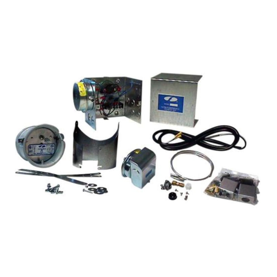
TEMS INCLUDED IN KIT
WARNING: Installer: if the 24V appliance does not have a blocked vent switch, an
additional GSK-3P spillage switch kit, p/n 46458600, (not included) must be installed
(See Diagram B).
24 VAC SYSTEM CONTROL KIT
Model: CK-92FVP and CK-92FGP
Designed for use with the SWG Series Power Venter for controlling
Natural Gas or L.P. Gas appliances equipped with a 24 VAC
automatic vent damper and a 30-millivolt controlled Natural or L.P.
Gas Water Heater.
:
1) Junction box with mounted pressure switch and post purge timer
1) Fan control gas pressure switch with built in post purge option
1) 2 ft. length of 1/4 inch aluminum tubing
1) 1/8" NPT x 3 inch pipe nipple
1) 1/8" NPT x 1/4 inch OD tubing elbow
1) 1/8" NPT pipe tee
1) TCA-1 Thermocouple Adaptor (CK-92FVP)
1) TCA-2 Left Handed Thermocouple Adaptor (CK-92FGP)
1) 6 ft. length of 12-2 wire
1) 8 inch jumper wire
2) Flexible conduit connector
2) GSK-3 Spillage Switch
1) 1/4 inch tubing connector
THESE INSTRUCTIONS MUST REMAIN WITH EQUIPMENT
DO NOT DESTROY
Advertisement
Table of Contents

Related Manuals for Field Controls 46490500


Summary of Contents for Field Controls 46490500
- Page 1 24 VAC SYSTEM CONTROL KIT Model: CK-92FVP and CK-92FGP Designed for use with the SWG Series Power Venter for controlling Natural Gas or L.P. Gas appliances equipped with a 24 VAC automatic vent damper and a 30-millivolt controlled Natural or L.P. Gas Water Heater.
- Page 2 INSTALLATION OUNTING ONTROL The control box must be mounted within 6’ of the vent damper, and within reach of the appliance’s existing damper cable. If the control box must be mounted out of reach of the power venter’s attached wiring, an additional installer supplied junction box and wiring (with approves wiring enclosure if necessary) will be required.
- Page 3 ADJUSTMENTS ROVING WITCH DJUSTMENTS After proper air flow is established, the pressure switch adjustment is made by turning the pressure switch adjustment screw clockwise (See Figure 4) until burner operation stops. Turn the adjustment screw counterclockwise until burner ignites. Turn the adjustment screw an additional 1/4 to 3/4 turn counterclockwise to ensure adequate switch adjustment.
- Page 4 NOTE: Draft spillage switches should be mounted 90 degrees apart, and mounted opposite from the vent outlet direction. (See Figure 9) 3. Mount the two spillage switches onto the draft hood and connect inside terminals of switches with jumper wire. Connect outside terminals to 6’...
- Page 5 Diagram B L1 to 1 on post purge timer T2 to timer relay base M to 3 on post purge timer T3 to N/O on pressure switch T1 to common on pressure switch Timer base to common on pressure switch OLTAGE IRING NSTRUCTIONS...
- Page 6 SYSTEM CONTROL CHECK OUT PROCEDURES 1. Adjust the thermostat and/or aquastat to call for heat and observe the power venting system for proper operation sequence. (Repeat if necessary) a. Aquastat calls for heat. b. After a short delay, the relay is energized, the venter motor starts and the vent damper begins opening. c.
- Page 7 REPAIR AND REPLACEMENT PARTS LIST MODEL PART NUMBER Gas Pressure Switch 46284200 GSK-3 Spillage Switch 46086400 Post Purge Timer 46282800 Pressure Switch 46273100 TCA-1 Thermocouple Adaptor 46082700 TCA-2 Left Handed Thermocouple Adaptor 46429900 Wire Harness 46457200 Page 7...
- Page 8 INSTALLATION INFORMATION CK-92FVP/CK-92FGP MODEL NO.:____________________________________________________________ INSTALLER'S NAME:_____________________________________________________ INSTALLER'S COMPANY: _________________________________________________ INSTALLER'S PHONE NO.: ________________________________________________ DATE OF INSTALLATION:_________________________________________________ Page 8 P/N 46490500 05/05...
Need help?
Do you have a question about the 46490500 and is the answer not in the manual?
Questions and answers